Hill 90C User manual

Hill 90C/Air90C Table
Owner’s Man al
Q ality and Innovation Since 1945.

Hill Laboratories Company has been making quality a family business since
1945. Your Hill 90C Table is built in a tradition of innovation and value that Hill
Laboratories products have become known for. Our good name rests on the
confidence that your Hill Table will provide you with solid, reliable service for
many years to come.
Con ratulations!
And welcome to the Hill Laboratories family.

Your Hill Laboratories table has been thoroughly tested and
inspected before shipment. All parts are guaranteed against defect
in materials for one full year from the date of purchase. Tables
damaged by mishandling or accident will be repaired at a reasonable
charge. All correspondence should be directed to your local dealer,
or when this is not possible, to Hill Laboratories directly.
We appreciate your business and your confidence in our products.
Our aim is to provide you with e cellent service and satisfaction for
many years to come.
Howard A. Hill
President, Hill Laboratories
At Your Service
The Hill Laboratories Guarantee.

© Copyr ght 2011, H ll Laborator es
Hill 90C Manual
Table of Contents
Product Features
Basic Table Components _________________________________________________1.1
Specifications __________________________________________________________1.2
Table Care
Cleaning your Table______________________________________________________2.1
Caution and Symbol Explanation __________________________________________2.2
Basic Table Operation
Preparing the 90C for Your Patient _________________________________________3.1
Height Pedal ___________________________________________________________3.2
Function Control Panel ___________________________________________________3.3
Thoracic Release/Thoracic Breakaway______________________________________3.4
Raised Pelvic ___________________________________________________________3.5
Usin Drops
Manual Drops __________________________________________________________4.1
Air Drops ______________________________________________________________4.2
Headpieces
Tilting Headpiece________________________________________________________5.1
Dual Drop Headpiece ____________________________________________________5.2
Raised Headpiece_______________________________________________________5.3
Cervical Flexion Headpiece _______________________________________________5.4
Maintenance and Trouble Shootin _____________________________Pages 8-9
Wirin Dia rams _____________________________________________Pages 10-12
Index of Terms _______________________________________________Pages 13-14

Product Features
1.1 Basic Table Components and ptions
1. Tilting Headpiece. May include several options.
2. Thoracic Drop with Thoracic Release. May include Breakaway.
3. Lumbar Drop
4. Pelvic Drop
5. Stationary Foot Section
6. Drop-Foot Section (optional)
7. Air-Control Foot Pedal for Thoracic Breakaway (air-models)
8. Power Foot Strip (air-models)
9. Rocker Foot Pedal for height adjustment (standard height pedal, also shown)
10. Armrest
11. Drop Tension Knobs
12. Function Control Panel (air-models)
13. Tension Control Handle for Manual Spring-Breakaway (caption)
14. Cocking Handle for Manual Drop
1.2 Specifications
•
Electric requirement 115 v~, 60 Hz, 2.7 A / Air90C - 7 A (or 230v~, 50 Hz)
Important: See note abo t sing a voltage reg lator on page 11
• Lifting capacity - 450 pounds
• Acrylic thermo-plastic base skirting
• Ultra-Cell®foam for comfort and shape retention
• Height Range - 90C: 22” - 35” / AirC: 211/2”-29” or 221/2”-31”
• Length - 90C: 5' 10"; with drop-away foot - 5' 1"
Air90C: 6' 1"; with drop-away foot - 5' 4"
Optional Slide-out Foot Section: removed - 5' 1"; inserted - 5' 4"; extended - 6'4"
• Standard width 24”, optional 27”, 30”
• Shipping weight approximately 250-300 lbs.
2
© Copyr ght 2011, H ll Laborator es
1
23
45
6
7
9
10
8
12
11
13 14

3
© Copyr ght 2011, H ll Laborator es
Table Care
2.1 Cleaning your Table
Hill table upholstery may be cleaned with Hill Laboratories' Vinyl and
Leather Cleaner or any household dishwashing liquid mixed with water. Hill
also offers Protex™Disinfectant Spray and wipes to protect against
pathogens, such as MRSA, HIV, Staph and the H1N1 Swine Flu Virus. Many
stubborn stains can be removed by applying 91% rubbing alcohol (isopropyl
alcohol) to the stain and wiping with a dry, soft, lint-free cotton cloth, towel or
soft bristle brush. Be sure to rinse thoroughly with water.
Caution: Some solvents are highly flammable; do not use near open flame
or intense heat. Wear rubber gloves during all cleaning activities. When
cleaning other parts of your table (besides upholstery) use only nonabra-
sive household detergents and water.
2.2 Caution and Symbol Explanation
Caution: Children should never be left alone in a room with the table but
should always be accompanied by an adult.
Caution: Always unplug the table before performing any maintenance.
Caution: Check table once a year to make sure all internal and external
bolts are secure.
Caution: The power cord should be located to avoid risk of tripping or
having objects rolled over or placed on top of it. Damaged cords should
be replaced with another of hospital grade.
Caution: rounding reliability can only be achieved when connected to an
equivalent receptacle marked hospital only or hospital grade.
Symbols
- Each of the symbols below are used in your table labeling.
An explanation of each is below.
~
Attention Symbol
consult accompanying
documents
Dangerous Voltage
Symbol
Type BF Applied
Part Symbol
Ground
Symbol
Alternating
Current
Symbol
Don t Touch
Symbol
© Copyright 2011, Hill Laboratories
Basic Table Operation
3.1 Preparing the 90C for your patient
Plug your table into any 110 volt grounded outlet (or 220 volt - international).
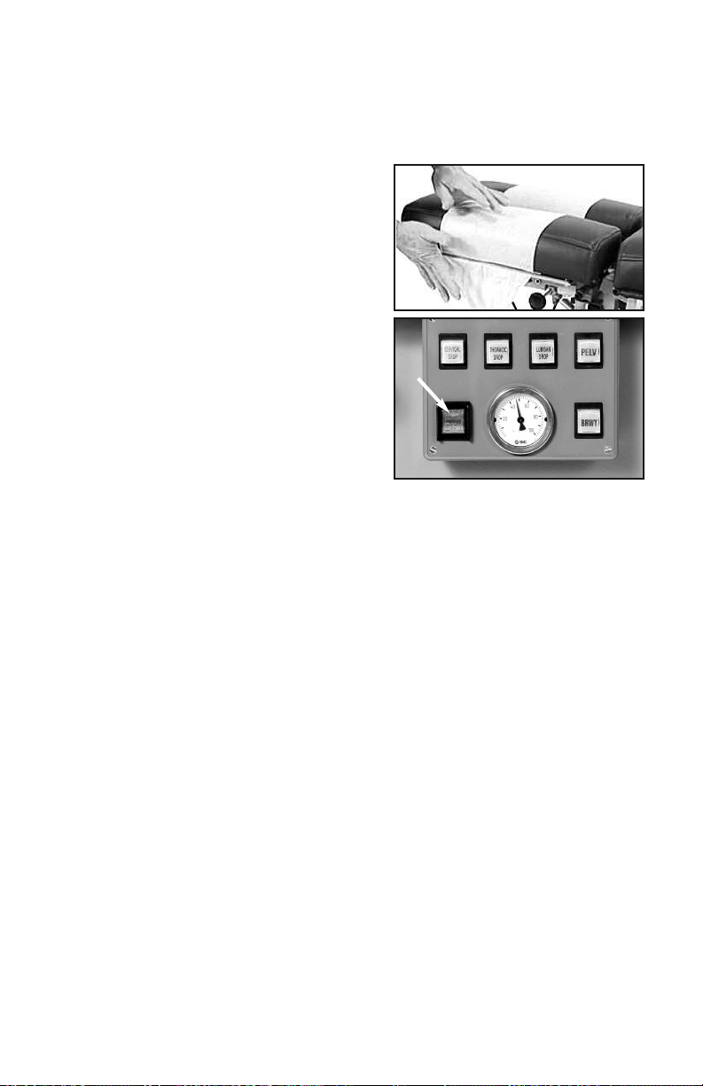
Paper Roll - Feed the paper through the face
cutout, around the paper bar (just below the
cutout) and over the headpiece (photo 1).
Close the paper cutter located on the side of
the headpiece and tear off excess paper.
Preparing the Air System (option)
For air models, press the Power button of
the main Control Panel (photo 3). Each of
the function buttons will light consecutively
and then turn off. The table’s air-compressor
may also turn on to replenish the air-supply.
The compressor will stop when the pressure
reaches 90 lbs.* See 4.2, “Using Air-Drops” for
air-feature instructions. *If the air-compressor
runs for more than 2-3 minutes, call for service
(see page 11).
Note: The Air90C is equipped with an Auto Shutdown mode which will power
down the main control board if the table is inactive for 2 hours. Press the green
power button to power the board back up.
3.2 Height Pedal
The basic 90C is equipped with a corded foot pedal which controls the height.
The Air90C features a dual Rocker Foot Pedal (#9 under “Product Features”)
which controls the table height from either side of the base. Press the right
side of either pedal to elevate; the left side to lower.
Auto-Touch Foot Pedal (option)
The Auto-Touch Foot Pedal option maintains upward or downward motion
after releasing the pedal. To operate:
- When the table is at the lowest height, double-touch the “UP” arrow and release.
The table will continue upward until you tap either side of the pedal again.
- When the table is at maximum height, double-touch the “DOWN” arrow and re-
lease. The table will continue downward until you tap either side of the pedal again.
- When the table is at any starting height in between, a single-touch up or down
will start and stop the motion.
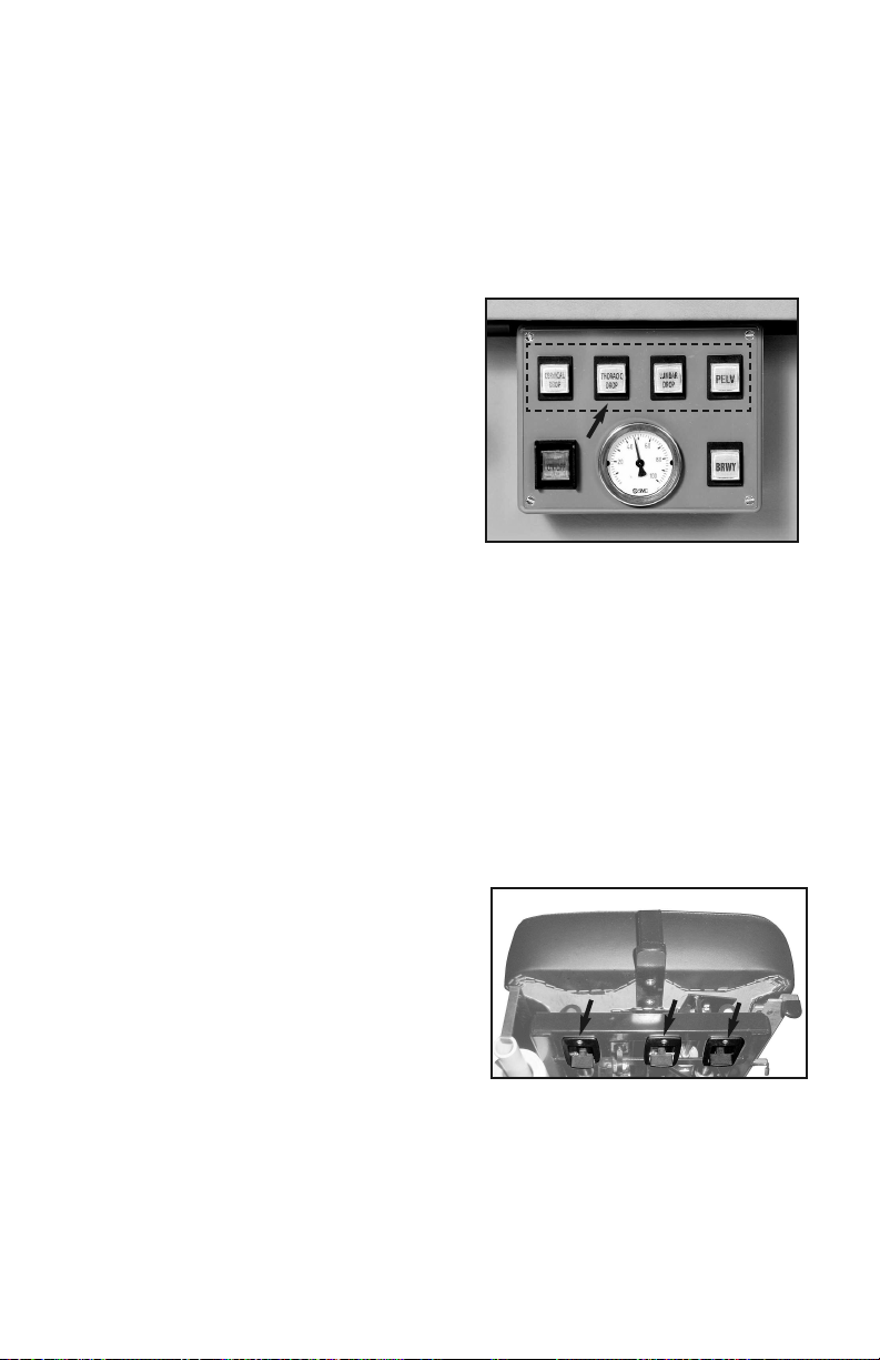
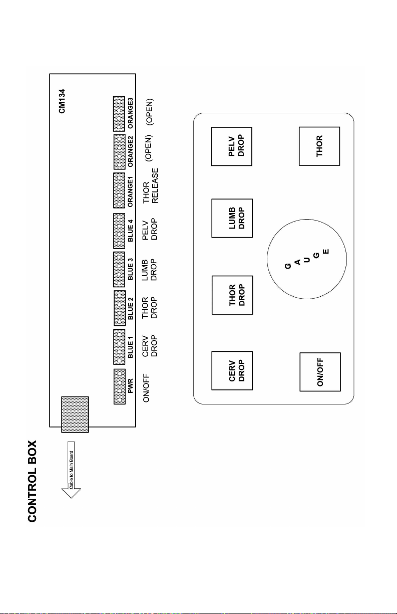
3.3 Function Control Panel
For Air90Cs, the control panel (photo 2) has a power switch, drop-selector
buttons and a thoracic-breakaway button (BRKY). After power, press in any order
to activate the corresponding function.
photo 2
photo 1
4
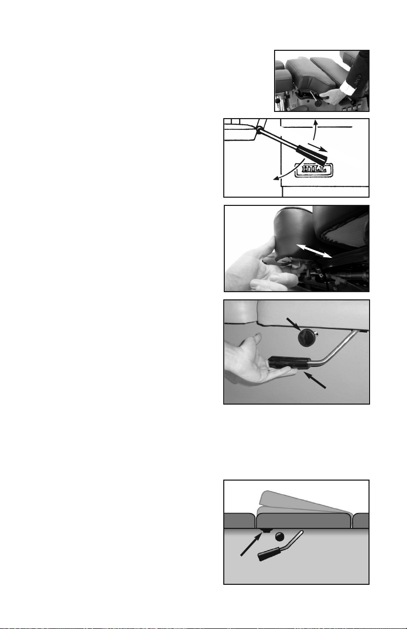
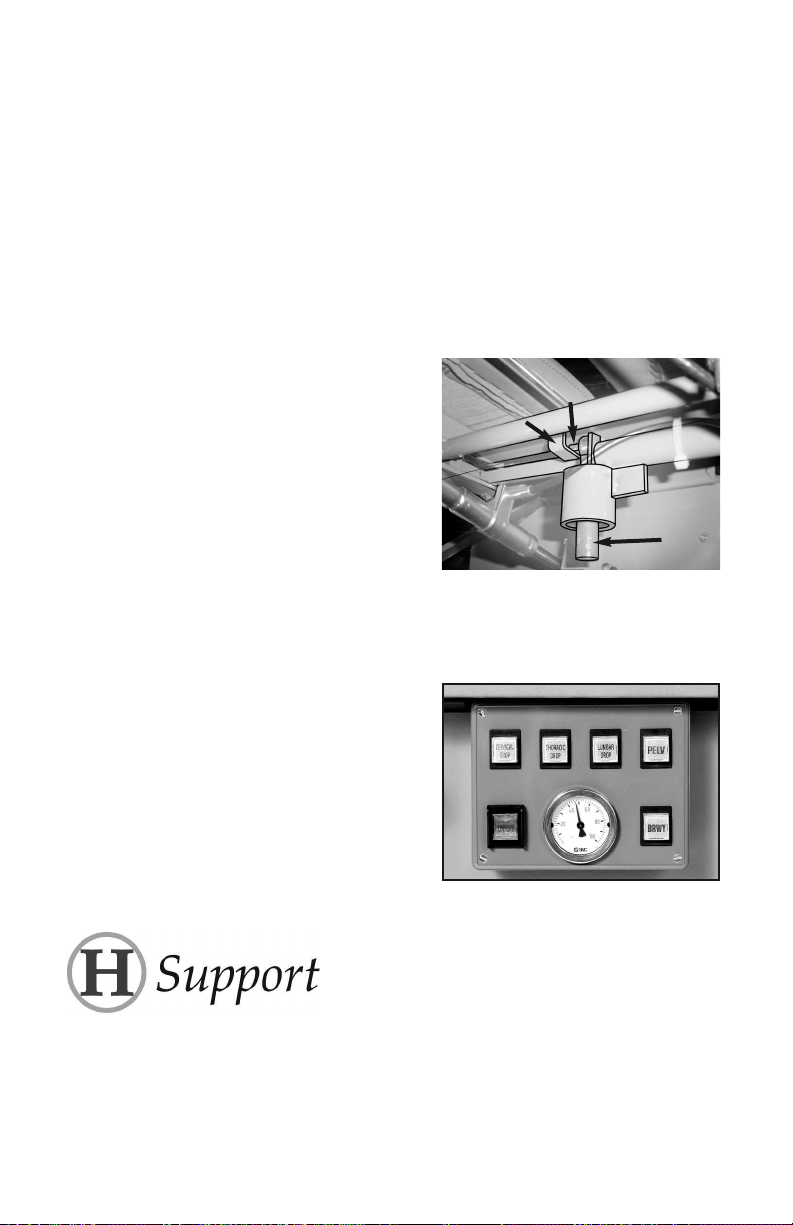
3.4 Thoracic Release / Thoracic Breakaway
Thoracic Release
To operate the Thoracic Release, pull the lever towards
you while holding the cushion; adjust to the desired
depth. Release the lever to lock the cushion.
Thoracic Spring-Breakaway
The manual Thoracic Breakaway
(non-air) uses a coiled spring to create
a recoil movement. First, unlock the
cushion (photo 4). Next, firmly pull out
on the tension control handle (photo 3)
to adjust firmness. Push down for
greater firmness; up for less. Push han-
dle back in to lock in desired firmness.
Thoracic Air-Breakaway
For tables with a Thoracic Air-Break-
away, it is necessary to regulate the
air-pressure before treating your
patient. Follow these steps:
1. Select the ‘BRKY’ (breakaway)
button on the main control panel
(photo 3).
2. Unlock the thoracic breakaway
switch by pulling toward you until it
clicks (photo 4). This will allow the
cushion to move freely up and down.
3. Press the right side of the Pressure
Foot Pedal (#7, page 2) to increase the air-pressure or left side to decrease
in the thoracic section. Push down on the cushion as you add air to test
for desired firmness.
4. Lock the cushion at any point by pushing the thoracic lock switch towards
the table until it clicks.
3.5 Raised Pelvic
Both the 90C and the AirC may be
equipped with an optional raised
pelvic section. To operate, locate the
lever under the cushion (photo 6, A).
Pull the lever toward you while you lift
the cushion. Release the lever to lock
it at the desired angle.
photo 4
Unlock
Lock
5
© Copyr ght 2011, H ll Laborator es
photo 3
Less f rm
More f rm
Pull handle to adjust
photo 5 A
B
photo 6
A
Usin Drops
4.1 Manual-Drops
Cocking handles are located on both sides of each drop. Lift the cocking
handle up (photo 5, A) to activate the drop. Turn the tension knobs (photo 5,B)
clockwise to tighten and counterclockwise to loosen (also see caution, pg. 6).
4.2 Air-Drops
Drop Selector Switches
The Drop Selector Switches (photo 7)
activate the table drops. You may choose
one or up to four drops simultaneously.
Once selected, press the foot strips (#8,
pg. 2) to activate the drops. After dis-
charging, press the pedal or foot strip
again to immediately reactivate the drops.
Drop Tension Control Knobs
The Drop Tension Knobs are located on the left side of each drop (#11, pg.
2). Turn the knob clockwise to increase the firmness of the drop—counter
clockwise to decrease.
Caution: Do not loosen Tension Knobs too far- Adjusting the tension knobs out too
far can cause the drops to malfunction. See “Tro ble Shooting” section on
pg. 10 for more detail.
Headpieces (options)
5.1 Tilting Headpiece
The lever for adjusting the tilting head-
piece is located under the front of the
headpiece (photo 8, A). It controls the
angle of tilt 30° positive or negative. Click
the switch in to lock; out to unlock.
5.2 Dual-Drop Headpiece
The Dual-Drop headpiece contains two drops—a drop-forward motion and a
straight-down drop.
Important Note: Before changing any of the settings described in the following
section, be sure the headpiece drop is discharged.
6
© Copyr ght 2011, H ll Laborator es
photo 7
Photo 8
A
CB
Headpiece
Drop-Forward Motion Headpiece
To use the Drop-Forward Motion of the
headpiece, the setting lever should re-
main in the side channel of the setting
mechanism as shown in photo 9. Be
sure that the pin locks into the receiver
behind it—otherwise, the drop will not
work. For a manual drop, push up on the
black cocking handle to engage.
For Air-Cervical Drop, see section 4.2.
Straight-Down Drop Headpiece
To use the Straight-Down Drop action of
the headpiece, pull the black setting
lever out and turn it to the left so that it
points straight down (photo 10). For a manual drop, push up on the black
cocking handle to engage.
For Air-Cervical Drop, see section 4.2).
5.3 Raised Headpiece
The Raised Headpiece allows the headpiece to rise up to 5” above the
surface of the table. It is controlled by a lever in front of the head cushion
(photo 8, B). Pull and hold the switch to adjust to the desired height; release
to lock. To lower, apply gentle downward pressure to the thoracic end of the
headpiece with one hand while pulling
the lever to adjust.
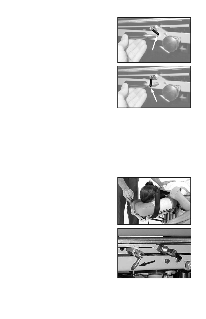
5.4 Cervical Flexion/Distraction
The Cervical Flexion Headpiece includes
the raised headpiece feature, occipital
strap and the removable tiller bar.
Note: Cervical Flexion, Distraction and
Lateral Motion (described below) can be
used separately or in combination.
Cervical Flexion
Position the patient as shown in photo 11.
Secure the occipital strap using the Velcro®
connectors. Use the Tiller Bar to apply flexion.
Cervical Distraction
To use Manual Cervical Distraction you must first unlock the cushion for axial
motion by releasing the red lock pin (photo 12). Pull and turn the lever to the left.
7
© Copyr ght 2011, H ll Laborator es
photo 11
photo 10
photo 9
photo 12

8
© Copyr ght 2011, H ll Laborator es
Cervical Lateral Motion
The Cervical Flexion Headpiece in-
cludes lateral motion. To use lateral
motion, locate the switch as shown in
photo 13 (or photo 8, C). Pull the lever
toward you to click and unlock. This
will allow full-range lateral movement.
The headpiece can also be locked at
any angle in the lateral range.
5.5 Translation/CBP Headpiece
To use the translation headpiece,
loosen the black knob in front of the
headpiece by turning it counterclock-
wise. Push the cushion left or right to
the desired position; turn clockwise to
tighten the knob. photo 14
photo 13
9
© Copyr ght 2011, H ll Laborator es
Maintenance
Regular Maintenance
Your Hill 90C is practically maintenance free. There is no lubrication of
parts needed.
Trouble Shootin
Problem
The Cervical Cushion cocks up but does not stay up. The drop pin has come out of
it’s L-bracket.
To Fix:
1. Loosen the Cervical Drop Tension
Knob enough to rotate the drop pin
(see “A” in photo) so that the spring
pin (B) faces and engages the
bracket (C) as shown in the photo.
Once the pin is turned into the
bracket, retighten the Tension Knob.
Problem
The main power board is turning off on it’s own. This is likely the Auto-Shutdown
mode operating normally.
When the Air90C is left inactive for 2
hours, the Auto-Shutdown mode will
power the main control board down
automatically.
To Fix:
Simply press the green power button.
Additional service needed? Contact your local dealer or reach us directly:
Phone: 1-877-445-5020
Fax: 610-647-6297
Email: Support@HillLabs.com
Technicians are available 9 am - 4 pm E.S.T., Monday - Friday.
A
B
C
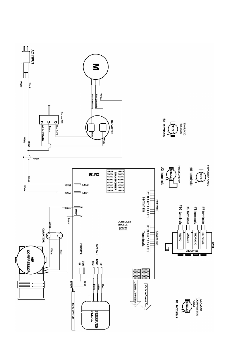
wire 3
Wiring Diagram - 90C, 24VDC, Part 1
Air System for all 90C Models.
10
© Copyr ght 2011, H ll Laborator es
Wiring Diagram - 90C, 24VDC, Part 2
Air System for all 90C Models.
11
© Copyr ght 2011, H ll Laborator es
Important:
Air functions on this table are controlled by a circuit board and
low voltage valves. Since electrical spikes, surges and undervolt-
age can be detrimental to electronic components, we recom-
mend protecting your table with an automatic voltage regulator.
While a voltage regulator will not guareantee parts against failure,
it could save you the cost of parts as well as table downtime.
The APC LE1200 voltage regulator is one example of a device
that would provide a minimum level of protection.
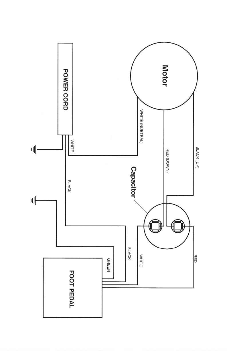
Wiring Diagram - 90C, 24VDC, Part 3
Height System for all 90C Models.
12
© Copyr ght 2011, H ll Laborator es

13
© Copyr ght 2011, H ll Laborator es
A
Air-Compressor 4
Armrests 2
Auto Shutdown 4, 9
Auto-Touch Foot Pedal 4
B
Basic Table Components 2
C
Cervical Distraction 7
Cervical Flexion 7
Cleaning your Table 3
Cautions and Symbols 3
Control Panel 2, 4, 5
D
Diagrams (See iring Diagrams)
Drops
- Manual 6
- Air Drops 6
- Not popping up 9
E
Electrical specifications 2
Electrical Schematics 10-12
F
Flexion (see Cervical Flexion)
Foot Pedal
- Corded 2, 4
- Rocker 2, 4
- Air-Pressure 2, 5
- Auto-Touch 4
Foot Strips 2, 6
Function Control Panel (See Control Panel)
H
Headpieces 2, 6-8
- CBP/Translation 8
H (continued)
- Cervical 7
- Dual-Drop 6
- Flexion 7
- Lateral Adjustment 8
- Raised 7
- Tilting 6
- Translation/CBP 8
Height Pedal 2, 4
Height Range 2
K
Knobs (See Tension Control Knobs)
L
Lateral Adjustment
- Cervical 8
Lifting Capacity 2
Locking Mechanisms
- Headpieces 6-8
- Lateral Flexion 7
- Thoracic Breakaway 5
- Thoracic Release 5
M
Manual Drops (See Drops)
N
Not orking (See Auto Shutdown)
O
On/Off Switch (See Power Button)
P
Paper Roll 4
Power Button 4, 9
Pressure Pedal 5
Problems (See Trouble Shooting)
R
Raised Headpiece (See Headpieces)
Index

14
© Copyr ght 2011, H ll Laborator es
S
Service and Support 9 and intro, “At Your Service”
Specifications 2
Surge Protection 11
T
Table Components 2
Tension Control Knobs 2, 6, 8
Thoracic Breakaway 2, 5
Thoracic Drop (see “Drops”)
Thoracic Release 2, 5
Translation Headpiece 8
Trouble Shooting 9
W
arranty See intro, “At Your Service”
iring Diagrams 10-12
Index

3 N. Bacton H ll Road, Frazer, PA 19355 • www.H llLabs.com
610-644-2867 • 1-877-445-5020 • Fax 610-647-6297
This manual suits for next models
1
Table of contents
Other Hill Indoor Furnishing manuals

Popular Indoor Furnishing manuals by other brands


OSP furniture
OSP furniture ASCEND II ACT3120 quick start guide

Coaster
Coaster 222724 Assembly instructions

dellonda
dellonda DH66 Assembly instructions

Nostalgia Electrics
Nostalgia Electrics HomeCraft HMCRCT135WH instruction manual

XONOX
XONOX OLIVER X03A5T65 installation instructions

Atlas Lighting Products
Atlas Lighting Products Guardian Pro MLGC180B user manual


