Hillphoenix ORIGIN2 ONIZ Owner's manual

INSTALLATION & OPERATION
CASES
HANDBOOK
P055547D
Rev. 10 11/05
MODEL: ONIZ
FROZEN FOOD/
ICE CREAM
COMPONENT


Welcome to the Hill PHOENIX display case family. We’re very pleased
you joined us.
This installation and operation handbook has been especially
prepared for everyone involved with Hill PHOENIX display cases – own-
ers, managers, installers and maintenance personnel.
You’ll find this book different than traditional manuals. The most
dramatic difference is the use of many more illustrated instructions to
make it easier to read and to help you get the most from this innovative
new design. When you follow the instructions you should expect
remarkable performance, attractive fits and finish, and long case life.
We are interested in your suggestions for improvement both in case
design and in this handbook. Please call/write to:
Hill PHOENIX
Marketing Services Department
1925 Ruffin Mill Rd.
Colonial Heights, VA 23834
Tel: 804-526-4455
Fax: 804-526-7450
or visit our web site at
www.hillphoenix.com
We wish you the very best in outstanding food merchandising and a
long trouble-free operation.


1
TABLE OF CONTENTS
GENERAL INFORMATION – PAGES 3 - 6
General information, first step recommendations and case dimensional drawings.
THE USE OF CASTERS – PAGE 7
LINE-UP – PAGES 8 - 9
An eleven step procedure for initial case lineup with illustrations.
TRIM-OUT – PAGES 10 - 11
An eleven step procedure for trimming out cases with illustrations.
REFRIGERATION PIPING – PAGE 12
Coil outlet locations, refrigeration components location, and other piping tips with
illustrations.
PLUMBING – PAGE 13
Information on drain connections.
ELECTRICAL HOOKUP AND WIRING DIAGRAMS – PAGES 14 - 18
Complete information on electrical connections.
CASE OPERATION – PAGE 19
Recommended settings for all case controls.
DEFROST AND TEMPERATURE CONTROL – PAGE 20
Defrost data and sensor bulb locations.
AIRFLOW & PRODUCT LOADING – PAGE 21
Air flow and load limits
USE AND MAINTENANCE – PAGES 22 - 23
Cleaning, and fan information
PARTS ORDERING – PAGES 24 - 26
Replacement parts identification
PRODUCT WARRANTY - Inside Back Cover

2

3
GENERAL INFORMATION
DESCRIPTION OF CASES: The refrigerated display cases described in this handbook
are part of the Hill PHOENIX, Origin2design series. Specifically covered in this manual is
model ONIZ, narrow island frozen food & ice cream.
STORE CONDITIONS: Hill PHOENIX cases are designed to operate in an air conditioned
store with a system that can maintain 75OF (24OC) store temperature and 55 percent (maxi-
mum) relative humidity (CRMA conditions). Case operation will be adversely affected by
exposure to excessively high ambient temperatures and/or humidity.
REFRIGERATION SYSTEM OPERATION: Air cooled condensing units require ventilation for
efficient performance of condensers. Machine room temperatures must be a minimum of
65OF in winter and a maximum of 95OF in summer. Minimum condensing temperatures
should be no less than 70OF.
RECEIVING CASES: Examine fixtures carefully for shipping damage and shortages. For
information on shortages contact the Service Parts Department at 1-800-283-1109.
APPARENT DAMAGE: A claim for obvious damage must be noted on the freight bill or
express receipt and signed by the carriers agent, otherwise the carrier may refuse the claim.
CONCEALED DAMAGE: If damage is not apparent until after the equipment is unpacked,
retain all packing materials and submit a written request to the carrier for inspection within
15 days of receipt of equipment.
LOST ITEMS: This equipment has been carefully inspected to insure the highest level of
quality. Any claim for lost items must be made to Hill PHOENIX within 48 hours of receipt
of equipment.
TECHNICAL SUPPORT: If any technical questions arise regarding a refrigerated display
case contact our Customer Service Department in Richmond at 1-804-526-4455. For any
questions regarding our refrigeration systems or electrical distribution centers contact our
Customer Service Department in Conyers at 1-770-285-3200.
CONTACTING FACTORY: Should you need to contact Hill PHOENIX regarding a specific
fixture, be sure to know the case model number and serial number. This information is on
the serial plate located on the rear baffle of the case (see next page for details). Ask for a
Service Parts Representative at 1-804-526-4455.

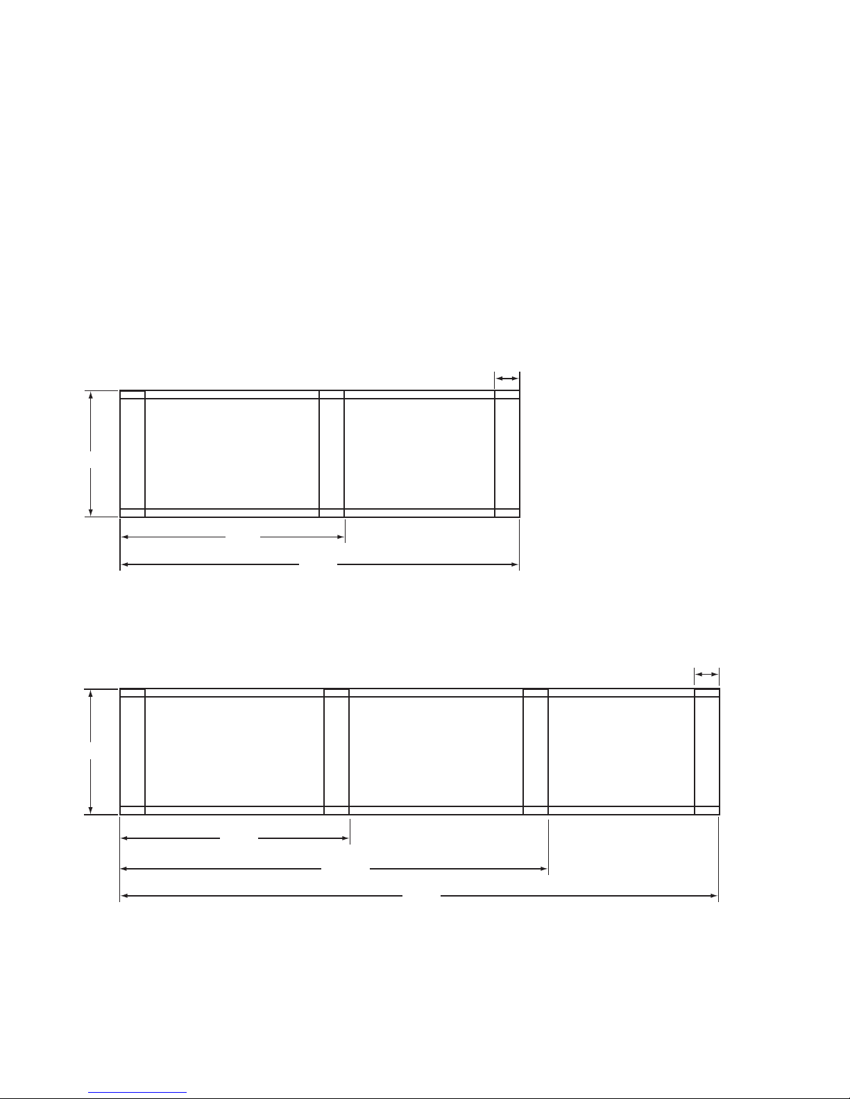
34 15/16 in
[88.8 cm]
5 in [12.7 cm]
COIL
PLENUM
13 3/8 in
[34.0 cm]
34 11/16 in [88.1 cm] FRONT OF CASE
26 15/16 in
[66.9 cm]
6 7/16 in [16.3 cm]*
9 11/16 in [24.6 cm]
17 3/8 in [44.2 cm]
22 1/2 in [57.1 cm]
45 in [114.3 cm]
C
L C
L
C
L
45 in
[114.2 cm]
22 1/2 in
[57.1 cm]
17 3/8 in
[44.1 cm]14 5/8 in
[37.1 cm]
9 11/16 in
[24.6 cm]
1 1/2 in [3.8 cm]
{FLAT END}
6 in [15.2 cm]
9 in [22.9 cm]
ELECTRICAL
WIRING-TO-RACEWAY
(STANDARD)
1 1/2" PVC DRAIN
CONNECTION
FRONT OF CASE
12 15/16 in
[32.9 cm]
**
22 1/2 in
[57.1 cm]
17 3/8 in
[44.1 cm]
9 11/16 in
[24.6 cm]
14 1/4 in
[36.1 cm]
REFRIGERATION
6 1/2 in [16.5 cm]
3 11/16 in [9.4 cm]
{WRAP END}
NOTES:
* STUB-UP AREA
** RECOMMENDED STUB-UP CENTERLINE FOR ELECTRICAL AND HUB DRAINS
zSUCTION LINE - 7/8", LIQUID LINE - 1/2"
72 in [182.9 cm] {6' case}
96 in [243.8 cm] {8' case}
120 in [304.8 cm] {10' case}
144 in [365.8 cm] {12' case}
C
L
9 5/8 in
[24.4 cm]
4
GENERAL INFORMATION
MODEL
ONIZ
(Standard Front)
Amp Plate &
Serial Plate
Location

5
5 in [12.7 cm]
COIL
PLENUM
FRONT OF CASE
6 7/16 in [16.3 cm]*
9 11/16 in [24.6 cm]
17 3/8 in [44.2 cm]
22 1/2 in [57.1 cm]
45 in [114.3 cm]
C
L
35 9/16 in
[90.3 cm]
12 7/16 in
[31.5 cm]
18 3/8 in
[46.7 cm]
13 5/8 in
[34.6 cm]
34 1/4 in [86.9 cm]
SOLID PANEL
C
L C
L
C
L
45 in
[114.2 cm]
22 1/2 in
[57.1 cm]
17 3/8 in
[44.1 cm]14 5/8 in
[37.1 cm]
9 11/16 in
[24.6 cm]
1 1/2 in [3.8 cm]
{FLAT END}
6 in [15.2 cm]
9 in [22.9 cm]
ELECTRICAL
WIRING-TO-RACEWAY
(STANDARD)
1 1/2" PVC DRAIN
CONNECTION
FRONT OF CASE
12 15/16 in
[32.9 cm]
**
22 1/2 in
[57.1 cm]
17 3/8 in
[44.1 cm]
9 11/16 in
[24.6 cm]
14 1/4 in
[36.1 cm]
REFRIGERATION
6 1/2 in [16.5 cm]
3 11/16 in [9.4 cm]
{WRAP END}
NOTES:
* STUB-UP AREA
** RECOMMENDED STUB-UP CENTERLINE FOR ELECTRICAL AND HUB DRAINS
zSUCTION LINE - 7/8", LIQUID LINE - 1/2"
72 in [182.9 cm] {6' case}
96 in [243.8 cm] {8' case}
120 in [304.8 cm] {10' case}
144 in [365.8 cm] {12' case}
9 5/8 in
[24.4 cm]
Amp Plate &
Serial Plate
Location
MODEL
ONIZ
(Glass Front)
19 1/2"
95 1/4"
143 1/4"
54 1/8"
97 13/32"
49 1/2"
8' CASE
12' CASE
FRONT OF CASE
FRONT OF CASE
19 1/2"
4"
4"
6
GENERAL INFORMATION
BASE HORSE
LOCATIONS FOR
MODELS
ONIZ
7
34
12
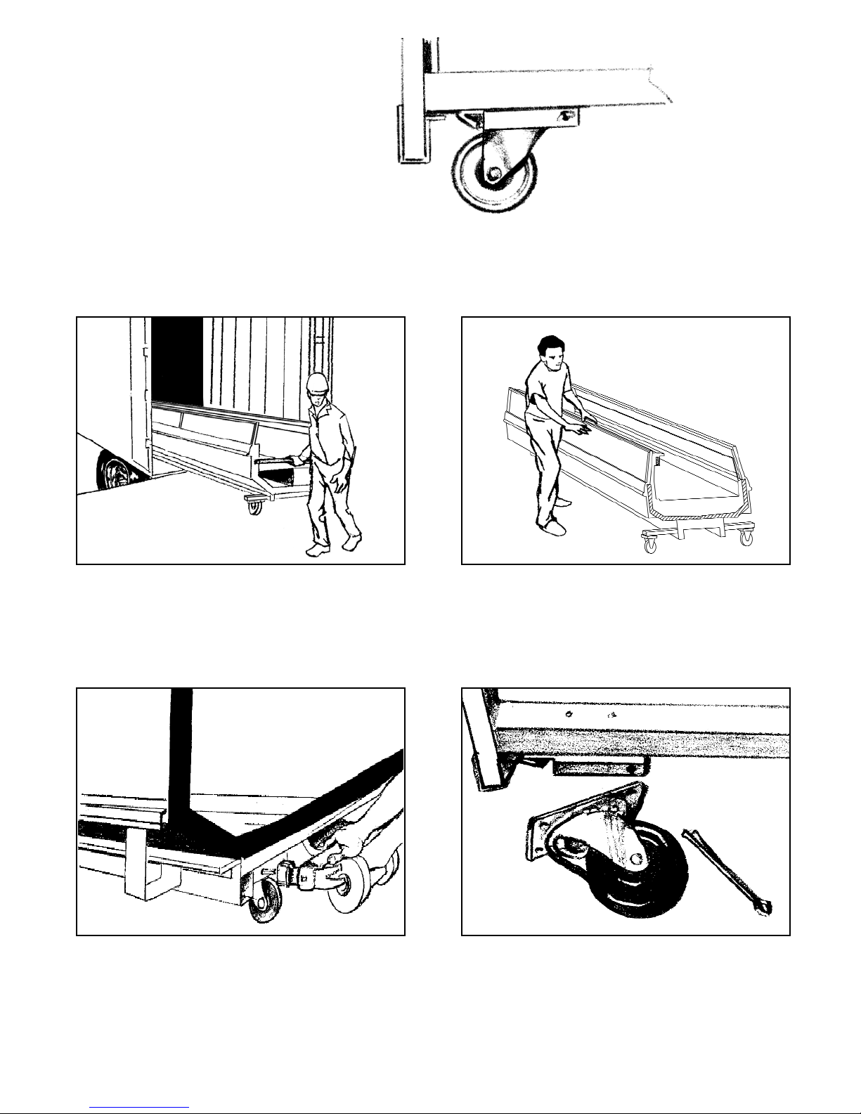
CASES
MOVE ON
CASTERS
FOR EASIER INSTALLATION
CASTERS MAY BE DISCARDED.
ROLL OUT OF TRUCK. When there is a truck - level
delivery dock, cases may be rolled directly from the
truck to the store floor. [CAUTION] If skid boards are
required to unload cases, casters should be removed
prior to sliding them down the skid; after which they
can be reinstalled on case.
ROLL TO LINEUP POSITION. Casters may remain in
place to move the cases to staging areas around the
store, prior to final installation. When ready for final
line-up, roll the case to set position, then remove
casters.
REMOVE COTTER PIN. Removing the casters is
easy. Simply flatten and hammer out cotter pins
then lift the case with “J” bar, and the casters will
fall off.
[CAUTION] Make certain hands are out of the way.
HILL PHOENIX cases are manufactured and shipped
to stores with casters installed on the base frame to
make the job of moving cases easier for everyone
involved with the manufacturing, shipping and instal-
lation process.
Casters not only speed up the process, but they also
reduce the chance of damage from raising and low-
ering cases with ”J” bar to place them on dollies,
skates or rollers. In most situations, one or two per-
sons can move the case with ease.
8
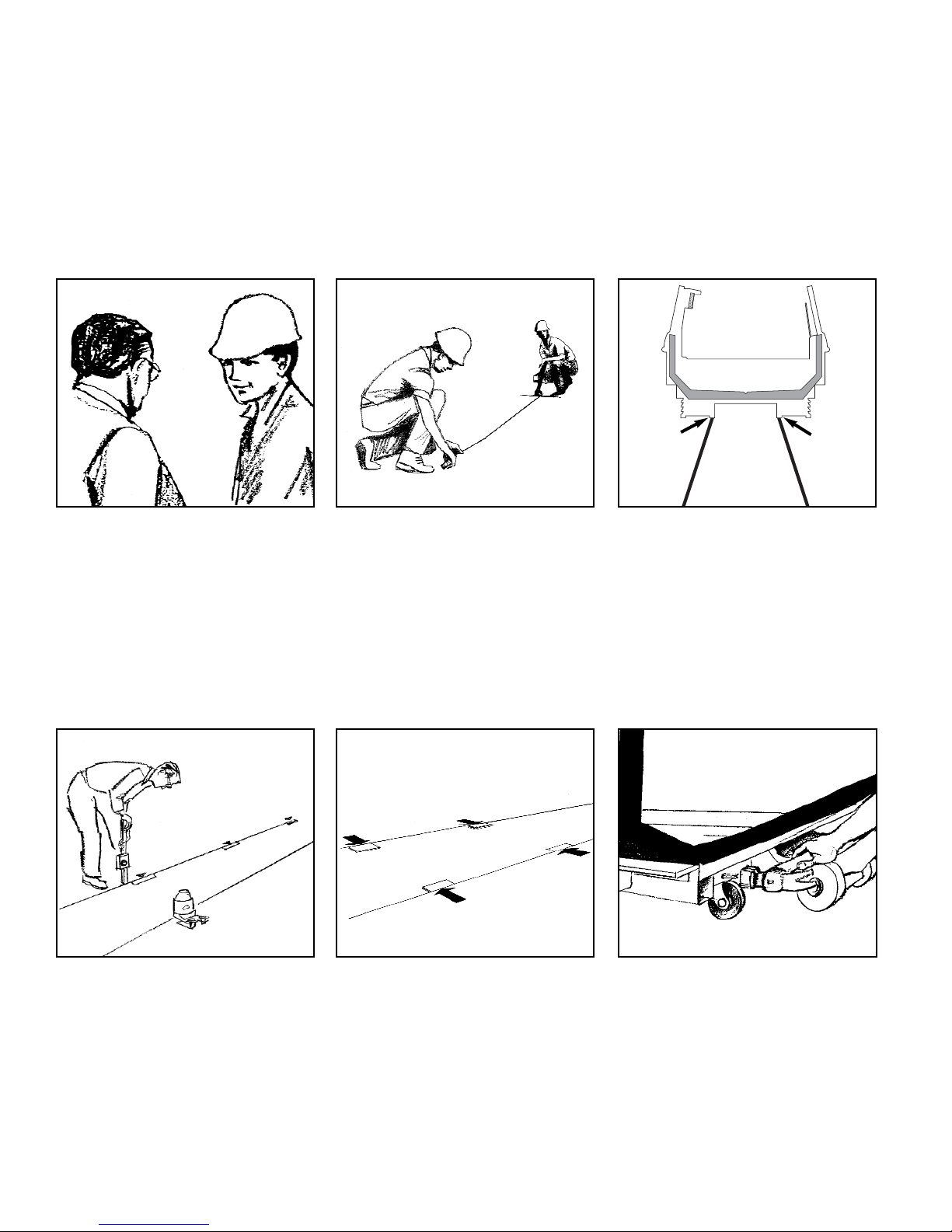
LINE UP
4
Level Floor. Use Laser Transit
Leveling is necessary to assure prop-
er case alignment. Locate highest
point on chalk line as reference for
determining height of shim-pack
levelers. A laser transit is recommend-
ed for precision and requires just one
person.
1
5
Consult With General Contractor
Ask the general contractor if there
have been changes in the building
dimensions since the print you are
using was issued. Also, ask the
points of reference from which you
should take dimensions to locate the
cases.
Set Shims On Joint Locations
Locate case joint positions along
chalk lines. Spot shim packs at each
joint location and at each base horse
between the joints.
2
Snap Chalk Lines
Mark floor where cases are to be
located for the entire lineup. 3
Snap Lines On Base Rail
Locations
Snap lines where base rails are posi-
tioned, not the front or back edges of
the cases. See case cross section
drawing, pages 4-6, for rail location
dimensions.
6
Position First Case In Lineup and
Level
Move first case into position. Raise
case from end under cross support
using “J” bar and remove the casters
[CAUTION! Keep hands from under-
neath case] Level case on shims.
BASE RAIL BASE RAIL

11
Bolt Cases Together Using Bolt
Holes Provided
Push cases tightly together. Bolt
cases together through the four holes
provided as shown in the illustration.
Tighten until all margins are equal; do
not over tighten.
10
Loosen Master Bumper
Loosen screws in master bumper.
Move bumper joint to a position for
sliding between adjoining case
bumper.
9
Remove Accessories From Case.
Add Sealant.
Remove anything from case that may
interfere with case joining (eg. ship-
ping braces). Run bead of sealant
around entire end before pushing
cases tightly together.
8
Position Next Case In Line Up
Roll the next case approximately 2’
from the adjoining case. Remove
casters on the end nearest to the next
case. Allow casters to remain on
opposite end to assist in pushing
cases together-then remove them
9
;;;;;;
;;;;;;
;;;;;;
;;;;;;
;;;;;;
;;;;;;
;;;
;;;
;;;
Ask about our case installation video available by request through your local Hill PHOENIX Sales or Field Service
Representative.
CAULK
7
Remove Outriggers
Remove cotter pin from outrigger by
cutting tie strap. Either pull the out-
rigger out from the front or insert a
crowbar into the tube from the back
and push the outrigger out.
COTTER PIN
LOCATION
OUTRIGGER
14
3
2
10
TRIM OUT
Now that cases have been positioned and leveled, you may proceed to trim-out
case lineup. Trim parts have been designed to be applied easily with only a small
number of fasteners required. Most external parts are adjustable to achieve almost
invisible, snug-fitting joints and a high level of excellence in fit and finish.
6
Install joint covers over case-to-case
joint seams, as needed. All case joint
pieces are shipped loose with the case.
Secure with fasteners provided.
;;;
;;;
;;;
;;;
;;;
;;;
;;;
;;;
;;;
;;;
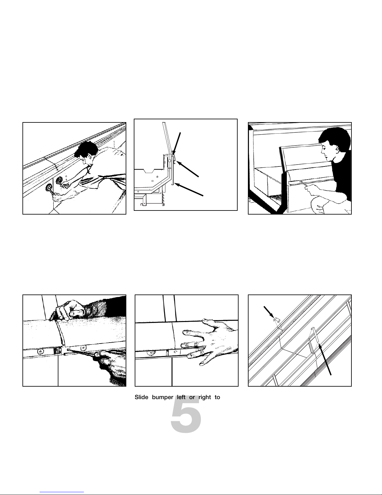
5
Slide bumper left or right to close
seam as required. Bumper joint neat-
ly finishes any gap that may remain.
4
Slide bumper joint to center of joint
between the two cases. Use screw
driver in hole provided.
3
Adjust polymer master bumper joints,
if required. First loosen bumper
screws located in recessed trough.
2
If a gap is present in the front panels,
the master bumper must be removed
to gain access to the adjustment
screws. Loosen the screws located
on top of the front panel underneath
the master bumper, and adjust left or
right as required.
1
Tighten all joint bolts. Draw up tight-
ly, but do not over tighten.
COLOR BAND ADJUSTMENT
SCREWS LOCATED UNDER
MASTER BUMPER
MASTER BUMPER
FRONT PANEL
REAR SILL
JOINT
GLASS
JOINT
11
Insert nose bumper into master
bumper channel. Roll nose bumper
into channel along entire lineup (up to
96’). We recommend that the nose
bumper be left in the store 24 hours
before installing. DO NOT STRETCH
the bumper during installation as it
will shrink to its original length and
leave a gap.
10
Insert kickplate into “J” rail. Slide the
kickplate up, behind the lower front
panel and then down on to the “J” rail.
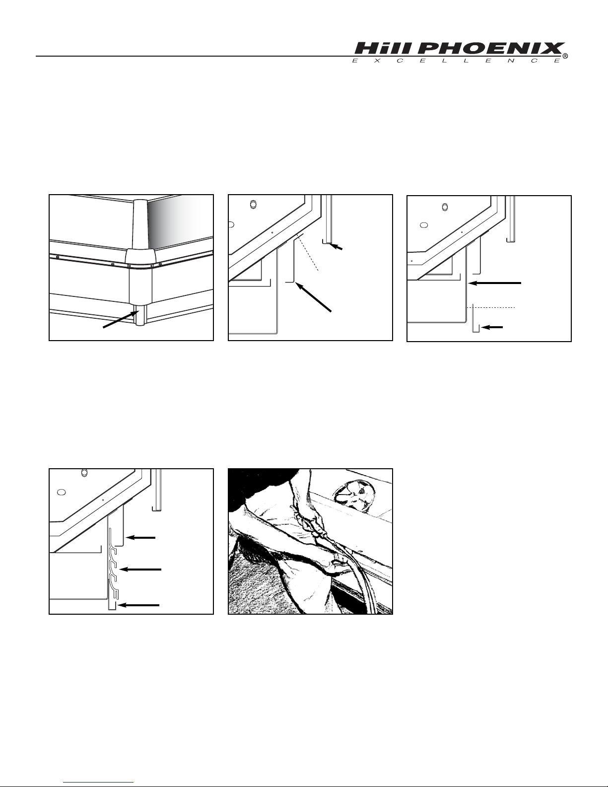
11
9
7Attach the “J” rail. Locate the “J” rail
which is shipped loose with the case.
Line up the rail to the kickplate brack-
ets and secure with the screws pro-
vided.
8
Attach pedestals. Locate the
pedestals which are shipped loose
with the case. Attach the pedestals to
each wrap end of the case with the
fasteners provided.
Attach lower front panel. Line up the
lower front panel directly under the
front panel. Screw the lower front
panel to the tank with the fasteners
provided.
NOTE: An easy technique for one
person is to press against nose
bumper with leg as you guide
bumper into channel with a screen
spline. Insert bottom first.
LOWER FRONT
PANEL
FRONT PANEL
PEDESTAL
KICKPLATE
BRACKET
SCREW
“J” RAIL
KICKPLATE
LOWER FRONT
PANEL
SCREW
“J” RAIL
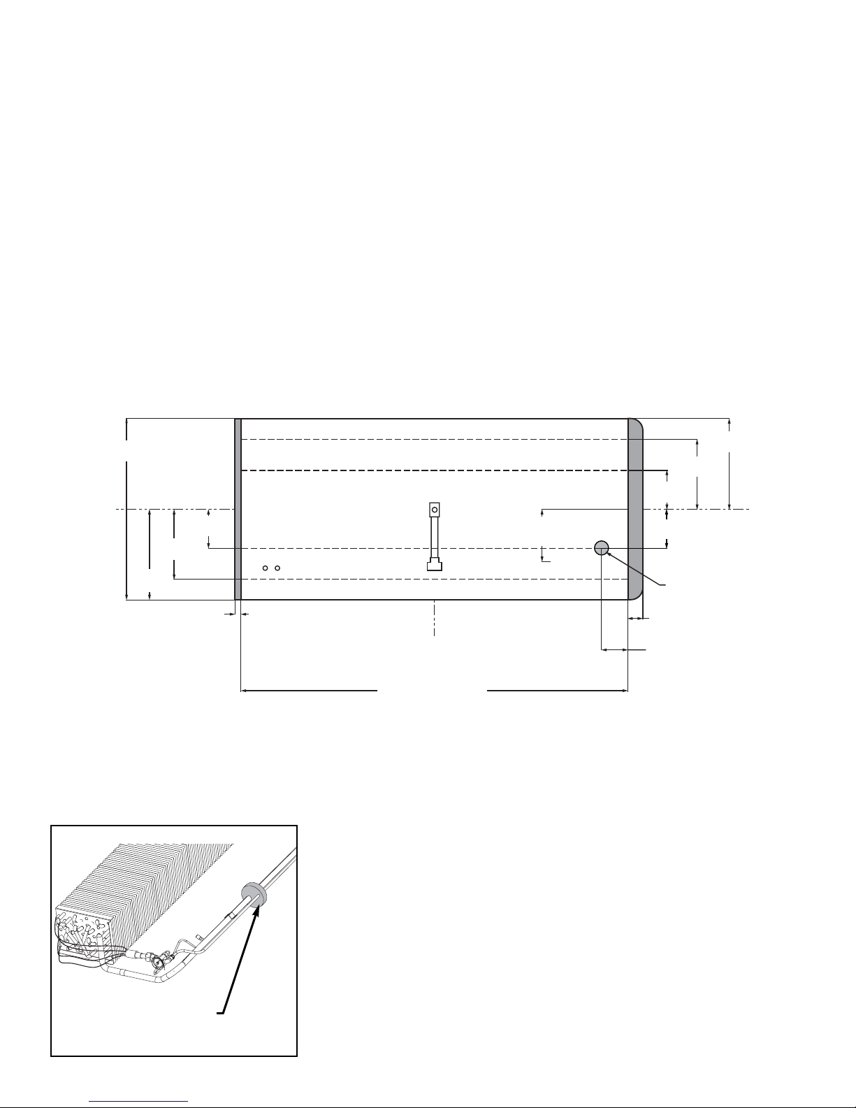
12
MODEL
ONIZ
REFRIGERATION PIPING
Refrigeration components and the
refrigeration outlet hole are located to provide
the best access for installation and mainte-
nance. As the diagram below indicates the coil
outlet hole is positioned forward on the right
hand side of the case, fully visible in front of the
fan plenum.
The expansion valve and other controls
are located on the left-hand side of the case
and are accessible without lifting the fan
plenum. The control cluster may be reached by
only lifting the left hand deck pan minimizing
the need to unload product.
Be sure to reseal the outlet hole after
installation, using a canned foam sealant and
white RTV
C
L C
L
C
L
45 in
[114.2 cm]
22 1/2 in
[57.1 cm]
17 3/8 in
[44.1 cm]
9 11/16 in
[24.6 cm]
1 1/2 in [3.8 cm]
{FLAT END}
FRONT OF CASE
12 15/16 in
[32.9 cm]
**
22 1/2 in
[57.1 cm]
17 3/8 in
[44.1 cm]
9 11/16 in
[24.6 cm]
3 11/16 in [9.4 cm]
{WRAP END}
NOTES:
** RECOMMENDED STUB-UP CENTERLINE FOR ELECTRICAL AND HUB DRAINS
zSUCTION LINE - 7/8", LIQUID LINE - 1/2"
72 in [182.9 cm] {6' case}
96 in [243.8 cm] {8' case}
120 in [304.8 cm] {10' case}
144 in [365.8 cm] {12' case}
REFRIGERATION
6 1/2 in [16.5 cm]
9 5/8 in
[24.4 cm]
REMOVE SHIPPING BLOCKS
REMOVE THE SHIPPING BLOCKS
THAT PROTECT THE REFRIGERATION
LINES DURING SHIPMENT BEFORE
OPERATING THE CASE.

13
PLUMBING
The drain outlet is located in the center
of the case just below the fan plenum. The
drain outlet is molded out of ABS material and
the “P” trap is constructed of schedule 40
PVC pipe. Care should be given to assure
that all connections are water tight and sealed
with the appropriate PVC cement, ABS
cement, or pipe dope.
The lower front panel and kickplate are
shipped loose with the case. If the kickplate has
already been installed, access to the drain area
can be easily obtained by removing it. See the
diagram below and the Trim Out section of this
manual on page 11.
HOW TO REMOVE KICKPLATE
C
L C
L
C
L
45 in
[114.2 cm]
22 1/2 in
[57.1 cm]
17 3/8 in
[44.1 cm]
9 11/16 in
[24.6 cm]
1 1/2 in [3.8 cm]
{FLAT END} 1 1/2" PVC DRAIN
CONNECTION
FRONT OF CASE
12 15/16 in
[32.9 cm]
**
22 1/2 in
[57.1 cm]
17 3/8 in
[44.1 cm]
9 11/16 in
[24.6 cm]
14 1/4 in
[36.1 cm]
3 11/16 in [9.4 cm]
{WRAP END}
NOTES:
** RECOMMENDED STUB-UP CENTERLINE FOR ELECTRICAL AND HUB DRAINS
72 in [182.9 cm] {6' case}
96 in [243.8 cm] {8' case}
120 in [304.8 cm] {10' case}
144 in [365.8 cm] {12' case}
“J” RAIL
LIFT FROM “J” RAIL AND PULL OUT
KICKPLATE
MODEL
ONIZ

14
ELECTRICAL HOOKUP
All electrical hookups are made to a
raceway located at the bottom front of the
case. Field connections can be made through
the bottom of the raceway.
The raceway is designed to allow
wiring to be run from case-to-case without
the use of “greenfield” or other conduit.
DEFROST HEATERS, 208/240 VOLTS L1
L2
RED
BLUE
EVAPORATOR FANS, 120 VOLT
ANTI-CONDENSATE HEATERS, 120 VOLT
WIRE NUMBERCOMPONENT COLOR CODING
BLACK
TEMPERATURE CONTROL, 120 VOLT
DEFROST TERMINATION CONTROL, 120 VOLT
WHITE
3
4
13
14
19
20
21
WHITE
BLACK
YELLOW
YELLOW
PURPLE
ORANGE23
WIRING NUMBERS AND COLORS
EQUIPMENT GROUNDING CONDUCTOR GREEN
-
C
L C
L
C
L
45 in
[114.2 cm]
22 1/2 in
[57.1 cm]
17 3/8 in
[44.1 cm]14 5/8 in
[37.1 cm]
9 11/16 in
[24.6 cm]
1 1/2 in [3.8 cm]
{FLAT END}
6 in [15.2 cm]
9 in [22.9 cm]
ELECTRICAL
WIRING-TO-RACEWAY
(STANDARD) FRONT OF CASE
12 15/16 in
[32.9 cm]
**
22 1/2 in
[57.1 cm]
17 3/8 in
[44.1 cm]
9 11/16 in
[24.6 cm]
3 11/16 in [9.4 cm]
{WRAP END}
NOTES:
** RECOMMENDED STUB-UP CENTERLINE FOR ELECTRICAL AND HUB DRAINS
72 in [182.9 cm] {6' case}
96 in [243.8 cm] {8' case}
120 in [304.8 cm] {10' case}
144 in [365.8 cm] {12' case}
CASE WIRING
ELECTRICAL
RACEWAY
MODEL
ONIZ

15
WIRING DIAGRAMS- MODEL
ONIZ-6’

16
WIRING DIAGRAMS- MODEL
ONIZ-8’
Table of contents
Other Hillphoenix Display Case manuals


