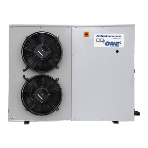
16 SoloChill Micro-Distributed Condensing Unit
6.3 Display Cases with Remote Mounted SoloChill Units
1. General
a. In applications where the SoloChill unit is mounted in a location that is remote from its associated display
case, additional wiring is required between the display case and the SoloChill unit. Of course, it will also be
necessary to run additional refrigeration piping between the two as well. This also means that systems must
be charged and leak checked in the eld.
b. In some instances there will be multiple evaporator coils in the display case lineup with a single SoloChill unit
being used to provide refrigeration for all. In applications such as these, the SoloChill unit controls the
operation of one primary (master) evaporator coil, and the other evaporator coils will each have a separate
controller. Note that each of these separate controllers requires its own, separate power supply.
c. Dual temperature operation is possible in some island case applications. When dual temperature operation
is included, the case section with the primary (master) evaporator must be operated at low temperature only,
but the other sections may be switched to operate at medium temperature conditions.
2. Installation
a. Power
i.
Power to the SoloChill unit is provided with a single-point, 4-wire (hot, hot, neutral, ground) 208V, single phase power input.
ii. Power for fans and heaters (defrost, anti-sweat, drain) for the master evaporator is provided from the
SoloChill unit.
iii. Smaller SoloChill units (DA091, DA130, DA220) will include a single breaker for overcurrent protection of the
case and SoloChill unit. Larger SoloChill units (DA330, DA420) will have two breakers for overcurrent
protection—one for case power and one for the SoloChill unit.
iv. See Figures 12 and 13 on the next page for the general wiring diagrams, and see Appendix B for the more
detailed wiring information (Fig. B-1 for larger units and Fig. B-2 for smaller units).
b. Sensors and EEV - Belden cable should be used for connecting temperature sensors and pressure
transducer in the display case to the SoloChill unit. See Appendix B for wiring details.
c. Water - See Section 4.0 for details on the water connections to the Solochill unit.
d. Network - In multi-evaporator display cases with remote SoloChill units, all controller are connected on the
Boss supervisory Communication Loop. Additionally, the Master and Slave controllers in the SoloChill and
case are connected on a second, pLAN Communication Loop. See Section 7.0 for details on the network
wiring connections to the SoloChill units.


