Hills NVC-BM1 User manual

0
Network Cameras
NVC-BM1
NVC-DF1
NVC-DT1
NVC-DM1
User Manual
V1.0

1
For further information, including full user and installation manual, and technical
support please visit:
www.hills.com.au/videosecurity

2
Table of Contents
Chapter 1 System Requirement....................................................................... 5
Chapter 2 Network Connection....................................................................... 6
2.1 Setting the Network Camera over the LAN........................................................ 6
2.1.1 Wiring over the LAN .........................................................................................................6
2.1.2 Detecting and Changing the IP Address............................................................................7
2.2 Setting the Network Camera over the WAN ...................................................... 8
2.2.1 Static IP Connection..........................................................................................................8
2.2.2 Dynamic IP Connection.....................................................................................................9
Chapter 3 Access to the Network Camera.......................................................13
3.1 Accessing by Web Browsers............................................................................ 13
3.2 Accessing by Client Software .......................................................................... 15
Chapter 4 Live View.......................................................................................17
4.1 Live View Page............................................................................................... 17
4.2 Starting Live View .......................................................................................... 18
4.3 Recording and Capturing Pictures Manually .................................................... 18
Chapter 5 Network Camera Configuration.....................................................20
5.1 Configuring Local Parameters ......................................................................... 20
5.2 Configuring Time Settings .............................................................................. 22
5.3 Configuring Network Settings ......................................................................... 24
5.3.1 Configuring TCP/IP Settings ............................................................................................24
5.3.2 Configuring Port Settings ................................................................................................25
5.3.3 Configuring PPPoE Settings.............................................................................................26
5.3.4 Configuring DDNS Settings..............................................................................................26
5.3.5 Configuring SNMP Settings .............................................................................................29
5.3.6 Configuring 802.1X Settings............................................................................................31
5.3.7 Configuring QoS Settings ................................................................................................31
5.3.8 Configuring UPnP™ Settings ...........................................................................................32
5.3.9 Email Sending Triggered by Alarm ..................................................................................33
5.3.10 Configuring NAT (Network Address Translation) Settings ..........................................35
5.3.11 Configuring FTP Settings ............................................................................................35
5.3.12 HTTPS Settings ........................................................................................................... 37
5.4 Configuring Video and Audio Settings............................................................. 39
5.4.1 Configuring Video Settings .............................................................................................39
5.4.2 Configuring Audio Settings .............................................................................................41
5.4.3 Configuring ROI Encoding ...............................................................................................41
5.5 Configuring Image Parameters........................................................................ 43

3
5.5.1 Configuring Display Settings ...........................................................................................43
5.5.2 Configuring OSD Settings ................................................................................................48
5.5.3 Configuring Text Overlay Settings ...................................................................................50
5.5.4 Configuring Privacy Mask................................................................................................51
5.5.5 Configuring Picture Overlay ............................................................................................52
5.6 Configuring and Handling Alarms ................................................................... 53
5.6.1 Configuring Motion Detection ........................................................................................53
5.6.2 Configuring Video Tampering Alarm ..............................................................................59
5.6.3 Configuring Alarm Input .................................................................................................60
5.6.4 Configuring Alarm Output ..............................................................................................61
5.6.5 Handling Exception .........................................................................................................62
5.6.6 Traversing V irtual Plane ..................................................................................................63
5.6.7 Configuring Intrusion Detection .....................................................................................65
5.6.8 Configuring Defocus Detection .......................................................................................66
5.6.9 Configuring Scene Change Detection .............................................................................66
5.7 VCA Configuration.......................................................................................... 67
5.7.1 Behavior Analysis............................................................................................................67
5.7.2 Face Capture ...................................................................................................................73
Chapter 6 Storage Settings.............................................................................77
6.1 Configuring NAS Settings................................................................................ 77
6.2 Configuring Recording Schedule ..................................................................... 79
6.3 Configuring Snapshot Settings ........................................................................ 83
Chapter 7 Playback........................................................................................86
Chapter 8 Log Searching...............................................................................89
Chapter 9 Others ...........................................................................................90
9.1 Managing User Accounts ................................................................................ 90
9.2 Authentication............................................................................................... 92
9.3 Anonymous Visit............................................................................................ 93
9.4 IP Address Filter............................................................................................. 94
9.5 Security Service ............................................................................................. 95
9.6 Viewing Device Information ........................................................................... 96
9.7 Maintenance ................................................................................................. 96
9.7.1 Rebooting the Camera ....................................................................................................96
9.7.2 Restoring Default Settings............................................................................................... 97
9.7.3 Exporting / Importing Configuration File........................................................................97
9.7.4 Upgrading the System.....................................................................................................98
9.8 Service Settings.............................................................................................. 98

4
Appendix...........................................................................................................100
Appendix 1 HVS Discovery Tool Software Introduction......................................... 100
Appendix 2 Port Mapping ...................................................................................... 103

5
Chapter 1 System Requirement
Operating System: Microsoft Windows XP SP1 and above version / Vista / Win7 /
Server 2003 / Server 2008 32bits
CPU: Intel Pentium IV 3.0 GHz or higher
RAM: 1G or higher
Display: 1024×768 resolution or higher
Web Browser: Internet Explorer 6.0 and above version, Safari 5.02 and above
version, Mozilla Firefox 3.5 and above version and Google Chrome8 and above
versions.

6
Chapter 2 Network Connection
Before you start:
Please refer to Section 2.1 Setting the Network Camera over the LAN to set the
network camera via a LAN (Local Area Network).
Please refer to Section 2.2 Setting the Network Camera over the WAN to set the
network camera via a WAN (WideArea Network).
2.1 Setting the Network Camera over the LAN
Purpose:
To view and configure the camera via a LAN, you need to connect the network
camera in the same subnet with your computer, and install the HVS Discovery Toll or
HVS PC Client software to search and change the IP of the network camera.
Note: For the detailed introduction of HVS Discovery Tool, refer to Appendix 1.
2.1.1 Wiring over the LAN
The following figures show the two ways of cable connection of a network camera
and a computer:
Purpose:
To test the network camera, you can directly connect the network camera to the
computer with a network cable as shown in Figure 2-1.
Refer to the Figure 2-2 to set network camera over the LAN via a switch or a
router.
Figure 2-1 Connecting Directly

7
Figure 2-2 Connecting via a Switch or a Router
2.1.2 Detecting and Changing the IPAddress
You need the IP address to visit the network camera.
Steps:
1. To get the IP address, you can choose either of the following methods:
Use HVS Discovery Toll, a software tool which can automatically detect the
online network cameras in the LAN and list the device information including
IP address, subnet mask, port number, device serial number, device version,
etc., shown in Figure 2-3.
Use the HVS PC Client software to list the online devices. Please refer to
the user manual of HVS PC Client software for detailed information.
2. Change the IP address and subnet mask to the same subnet as that of your
computer.
3. Enter the IP address of network camera in the address field of the web browser to
view the live video.
Notes:
By default DHCP is enabled, camera will search for DHCP server for a
duration of 30 seconds. If there isn’t DHCP server in the network then use
default fixed IP address.
Default Fixed IP address is “10.1.1.1” and Subnet mask is “255.0.0.0”. The
default user name is “admin”, and password is “admin”.
For accessing the network camera from different subnets, please set the
gateway for the network camera after you log in.

8
Figure 2-3 HVS Discovery Toll Interface
2.2 Setting the Network Camera over the WAN
Purpose:
This section explains how to connect the network camera to the WAN with a static IP
or a dynamic IP.
2.2.1 Static IP Connection
Before you start:
Please apply a static IP from an ISP (Internet Service Provider). With the static IP
address, you can connect the network camera via a router or connect it to the WAN
directly.
Connecting the network camera via a router
Steps:
1. Connect the network camera to the router.

9
2. Assign a LAN IP address, the subnet mask and the gateway. Refer to Section 2.1.2
Detecting and Changing the IP Address for detailed IP address configuration of
the camera.
3. Save the static IP in the router.
4. Set port mapping, e.g., 80, 8000, and 554 ports. The steps for port mapping vary
according to the different routers. Please call the router manufacturer for
assistance with port mapping.
Note: Refer to Appendix 2 for detailed information about port mapping.
5. Visit the network camera through a web browser or the client software over the
internet.
Figure 2-4 Accessing the Camera through Router with
Static IP
Connecting the network camera with static IPdirectly
You can also save the static IP in the camera and directly connect it to the internet
without using a router. Refer to Section 2.1.2 Detecting and Changing the IP Address
for detailed IP address configuration of the camera.
Figure 2-5 Accessing the Camera with Static IP Directly
2.2.2 Dynamic IP Connection
Before you start:
Please apply a dynamic IP from an ISP. With the dynamic IP address, you can connect
the network camera to a modem or a router.

10
Connecting the network camera via a router
Steps:
1. Connect the network camera to the router.
2. In the camera, assign a LAN IP address, the subnet mask and the gateway. Refer
to Section 2.1.2 Detecting and Changing the IP Address for detailed LAN
configuration.
3. In the router, set the PPPoE user name, password and confirm the password.
4. Set port mapping. E.g. 80, 8000, and 554 ports. The steps for port mapping vary
depending on different routers. Please call the router manufacturer for assistance
with port mapping.
Note: Refer to Appendix 2 for detailed information about port mapping.
5. Apply a domain name from a domain name provider.
6. Configure the DDNS settings in the setting interface of the router.
7. Visit the camera via the applied domain name.
Connecting the network camera via a modem
Purpose:
This camera supports the PPPoE auto dial-up function. The camera gets a public IP
address by ADSL dial-up after the camera is connected to a modem. You need to
configure the PPPoE parameters of the network camera. Refer to Section 5.3.3
Configuring PPPoE Settings for detailed configuration.
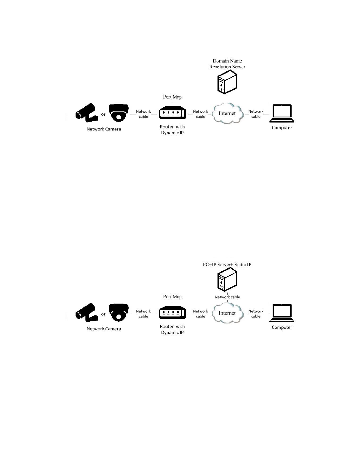
Figure 2-6 Accessing the Camera with Dynamic IP
Note: The obtained IP address is dynamically assigned via PPPoE, so the IP address
always changes after rebooting the camera. To solve the inconvenience of the
dynamic IP, you need to get a domain name from the DDNS provider (E.g.
DynDns.com). Please follow the steps below for normal domain name resolution and
private domain name resolution to solve the problem.
11
Normal Domain Name Resolution
Figure 2-7 Normal Domain Name Resolution
Steps:
1. Apply a domain name from a domain name provider.
2. Configure the DDNS settings in the DDNS Settings interface of the network
camera. Refer to Section 6.3.4 Configuring DDNS Settings for detailed
configuration.
3. Visit the camera via the applied domain name.
Private Domain Name Resolution
Figure 2-8 Private Domain Name Resolution
Steps:
1. Install and run the IP Server software in a computer with a static IP.
2. Access the network camera through the LAN with a web browser or the client
software.
3. Enable DDNS and select IP Server as the protocol type. Refer to Section 6.3.4
Configuring DDNS Settings for detailed configuration.

12

13
Chapter 3 Access to the Network
Camera
3.1 Accessing by Web Browsers
Steps:
1. Open the web browser.
2. Input the IP address of the network camera in the address bar, e.g., 10.1.1.1 and
press the Enter key to enter the login interface.
3. Input the user name and password and click Login.
Figure 3-1 Login Interface
Notes:
The default user name is admin, and the default password is admin.
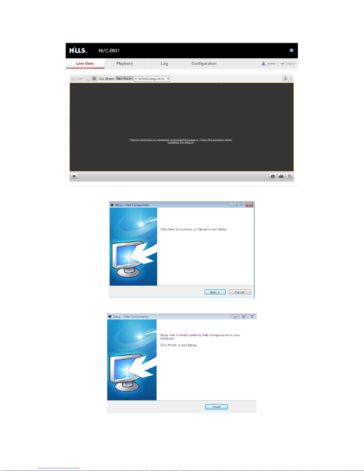
4. Install the plug-in before viewing the live video and operating the camera. Please
follow the installation prompts to install the plug-in.
14
Figure 3-2 Download and Install Plug-in
Figure 3-3 Install Plug-in (1)
Figure 3-4 Install Plug-in (2)

15
Note: You may have to close the web browser to install the plug-in. Please reopen the
web browser and log in again after installing the plug-in.
3.2 Accessing by Client Software
Download HVS PC Client software from website www.hills.com.au/videosecurity.
You can view the live video and manage the camera with the software.
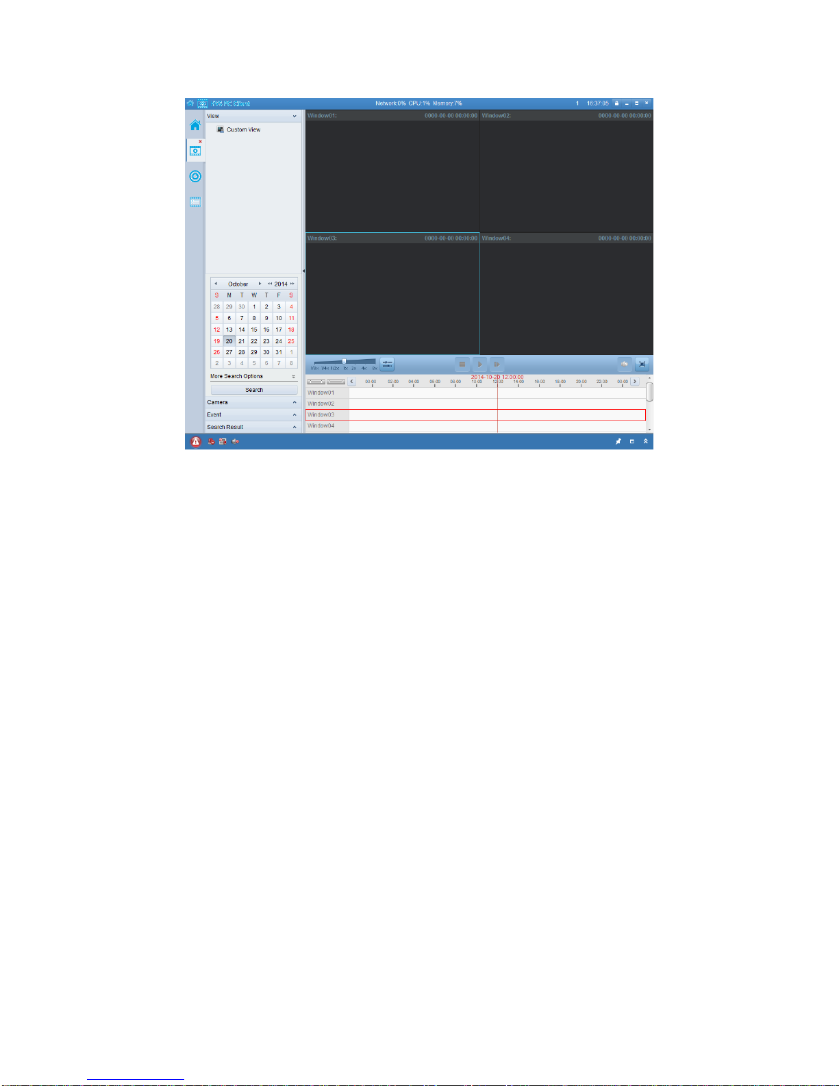
Follow the installation prompts to install the software. The control panel and live view
interface of HVS PC Client software are shown as bellow.
Figure 3-5 HVS PC Client Control Panel
16
Figure 3-6 HVS PC Client Configuration Panel
Note: For detailed information about the software, please refer to the user manual of
the HVS PC Client.

17
Chapter 4 Live View
4.1 Live View Page
Purpose:
The live view page allows you to view the real-time video, capture images, realize
PTZ control, set/call presets and configure video parameters.
Log in the network camera to enter the live view page, or you can click Live View on
the menu bar of the main page to enter the live view page.
Descriptions of the live view page:
Figure 4-1 Live View Page
Menu Bar:
Click each tab to enter Live View, Playback, Log and Configuration page
respectively.
Display Control:
Click each tab to adjust the layout and the stream type of the live view. And you can
click the drop-down to select the plug-in. For IE (internet explorer) user,
webcomponents and quick time are selectable. And for Non-IE user, webcomponents,
quick time, VLC or MJPEG is selectable if they are supported by the web browser.
Live View Window:
Display the live video.
18
Toolbar:
Operations on the live view page, e.g., live view, capture, record, audio on/off,
two-way audio, etc.
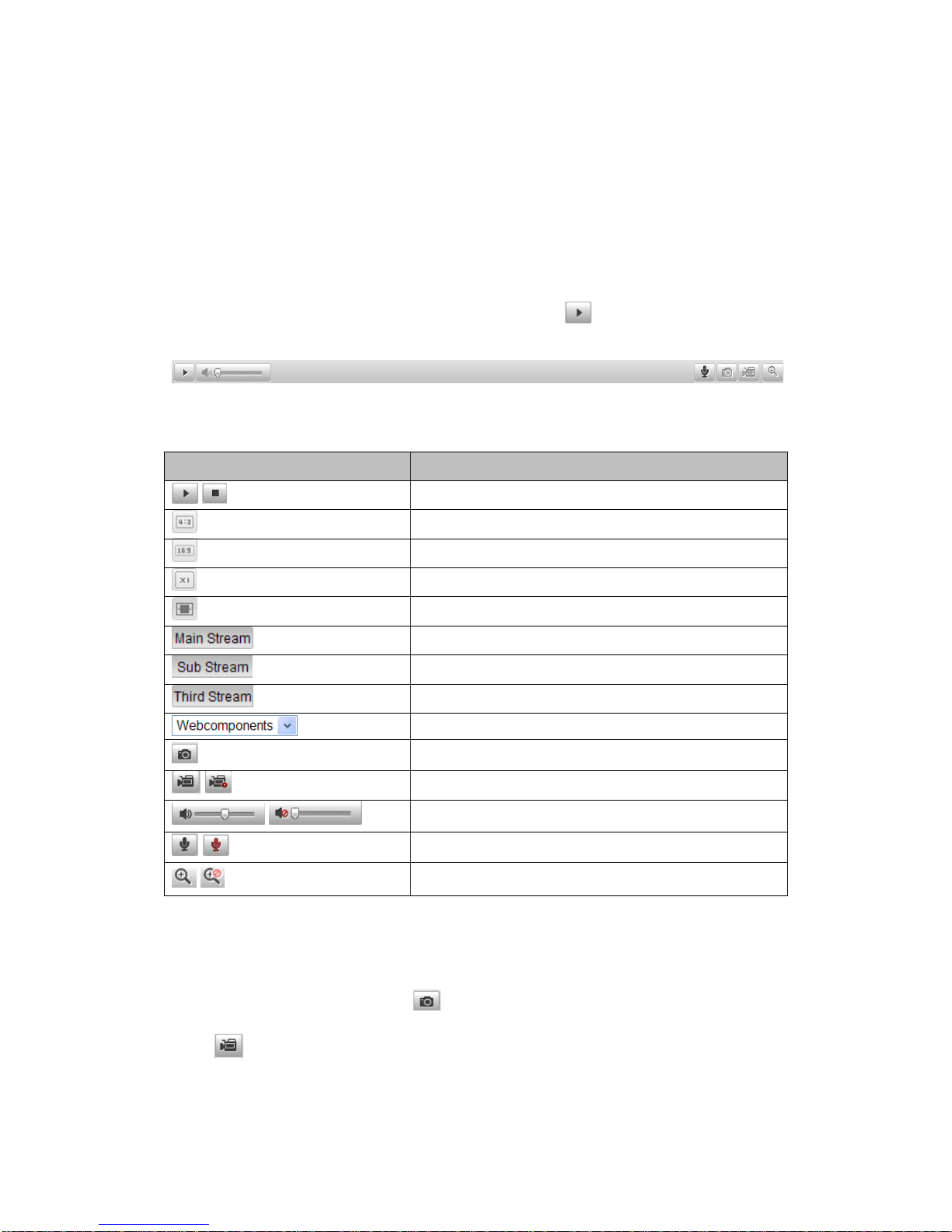
4.2 Starting Live View
In the live view window as shown in Figure 5-2, click on the toolbar to start the
live view of the camera.
Figure 4-2 Live View Toolbar
Table 4-1 Descriptions of the Toolbar
Icon
Description
/
Start/Stop live view.
The window size is 4:3.
The window size is 16:9.
The original widow size.
Self-adaptive window size.
Live view with the main stream.
Live view with the sub stream.
Live view with the third stream.
Click to select the third-party plug-in.
Manually capture the picture.
/
Manually start/stop recording.
/
Audio on and adjust volume /Mute.
/
Turn on/off microphone.
/
Turn on/off 3D zooming function.
4.3 Recording and Capturing Pictures Manually
In the live view interface, click on the toolbar to capture the live pictures or
click to record the live view. The saving paths of the captured pictures and clips
can be set on the Configuration > Local Configuration page. To configure remote

19
scheduled recording, please refer to Section 7.2.
Note:The captured image will be saved as JPEG file or BMP file in your computer.
Other manuals for NVC-BM1
2
This manual suits for next models
3
Table of contents
Other Hills Security Camera manuals


/HD21 manual")


