Hilltip Ice STRIKER 600 TR User manual

STRIKER
TM
Owner’s manual
600-1000 LITER POLY ELECTRIC TRACTOR SPREADER
19 November, 2021
Version 1.2
This manual replaces all editions with an earlier date.

2
IceStrikerTM
GENERAL INFORMATION ............................................ 3
Spreader parts .................................................. 3
Technical information ............................................. 4
SAFETY INFORMATION.............................................. 5
Safetydenitions ................................................ 5
Safety precautions ............................................... 5
Recommended vehicle requirements ................................. 6
Noise ......................................................... 6
Personal safety.................................................. 6
Emergency stop ................................................. 6
Warning and caution labels ........................................ 7
INSTALLATION AND OPERATION ..................................... 8
Control placement ............................................... 8
Vehicle side harness cable kit ...................................... 8
Accessory cables ................................................ 9
Mounting the top screen ........................................... 9
Mounting the Tarp cover assembly...................................10
Spreading pattern ................................................12
Rotate jammed auger manually .....................................12
LOADING ..........................................................13
Average material weights ..........................................13
Filling the integrated pre-wet tank ...................................13
MAINTENANCE .....................................................14
Maintaining the spreader ..........................................14
Storage ........................................................15
OPTIONAL LIQUID SYSTEMS.........................................16
Pre-wet (optional) ................................................16
Spray-bar (optional) ..............................................17
Bladder tank (optional) ............................................18
Hose reel (optional) ..............................................19
Liquid system clean-out instructions..................................19
ELECTRICAL SCHEMATIC ...................................... . . . . . 20
WARRANTY INFORMATION ..................................... . . . . . 21
CERTIFICATE OF CONFORMITY ................................. . . . . . 22
Read this manual before installing or
operating the spreader
CAUTION
!
3
IceStrikerTM
GENERAL INFORMATION
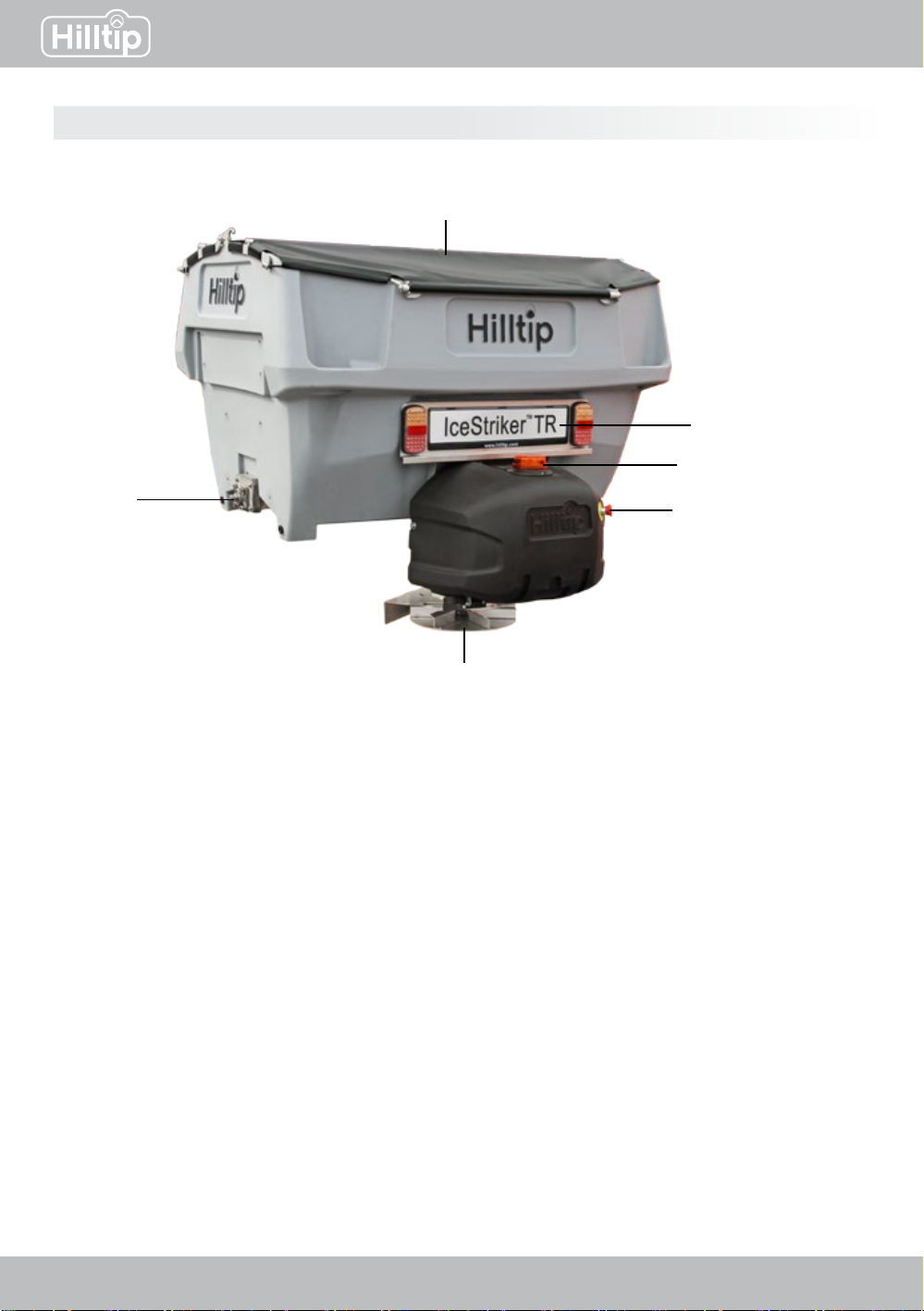
Spreader parts
Tarp cover
License plate kit and
rear light (optional)
Beacon light (optional)
Emergency stop button
Spinner
Auger
(inside hopper)

4
IceStrikerTM
Technical information
SPREADER SPECIFICATIONS 600 TR 800 TR 1000 TR
Overall width 1500 mm 1500 mm 1500 mm
Height 1500 mm 1650 mm 1800 mm
Capacity (water level) 550 l 750 l 950 l
Capacity (rounded) 630 l 850 l 1050 l
Weight (empty) 320 kg 360 kg 390 kg
Hopper construction Poly Poly Poly
Spreading width 1-8 m (may vary depending on material)
Spinner size 390 mm 390 mm 390 mm
Auger diameter 65 mm 65 mm 65 mm
Vibrator YES YES YES
GPS speed control YES YES YES
Vehicle Tractors/loaders
Material Salt, sand, granulat, mixed
OPTIONAL LIQUID SYSTEM 600 TR 800 TR 1000 TR
Pre-wet, Spray volume 3-12 l/min 3-12 l/min 3-12 l/min
Spraybar, Spray volume 5-25 l/min 5-25 l/min 5-25 l/min
Pre-wet, Spraying width 1-8 m (together with spreading material)
Spraybar, Spraying width 2-5 m 2-5 m 2-5 m
Pre-wet, liquid tank capacity 330 l 330 l 330 l
Spraybar, liquid tank capacity 330/900 l * 330/900 l * 330/900 l *
Spraying material Anti- and de-icing liquids, water, liquid fertilizers **

5
IceStrikerTM
Technical information
Implies a potentially hazardous
situation that, if not avoided, could
result in death or serious personal
injury.
Implies a potentially hazardous
situation that, if not avoided, may
result in minor or moderate injury.
It may also be used to alert against
unsafe practices.
Implies a situation or action that can
lead to damage to your spreader and
vehicle or other property. Other useful
information can also be described.
Safety denitions
1. Read this manual before operating the
spreader.
2. Before operating, make sure all the
equipment is securely mounted into place.
3. Check that there are no persons within the
spreader spray area when starting and
operating this spreader.
4. Do not exceed your vehicle total weight
beyond payload limits.
5. Alwaysturnothespreader before
cleaning, lubricating or unclogging
material jambs.
6. Never climb or ride on or in the spreader.
7. Ensure that you have fastened the
spreader to the vehicle according to
descriptions in this manual.
8. A spreader in need of repairs or
maintenance should not be operated.
9. Before removing or replacing any
electrical components, always disconnect
the battery.
10.Donotkeepgasolineorotherammable
liquids on the truck bed while spreader is
mounted on the truck bed.
Observe these safety precautions
before, during and after operating the
spreader. You can prevent injury to
persons and damage to the spreader
by following these precautions.
SAFETY INFORMATION
Safety precautions
Incorrect installation and operation can lead
to serious personal injury and/or damage
your equipment and property. Note and
ensure that you understand this manual and
all the labels before installing, operating or
making adjustments to the spreader.
!WARNING
iNOTE
!WARNING CAUTION
!

6
IceStrikerTM
Always keep bystanders a minimum
of 10 meters away when operating the
spreader.
Empty and clean the hopper after each
use. Unused spreading material left in
hopper could freeze or solidify, causing
the spreader to not work properly.
Use a good quality multi-purpose
greasetolubricategreasettingsafter
each use.
• To prevent accidents, secure long hair and do not wear jewelry or necktie, only wear tight-tting
clothes while working on your spreader or vehicle.
• Protect your eyes with safety goggles to avoid damage from battery acid, gasoline, dirt and dust.
• Always handle the solid and liquid materials carefully. Wear safety goggles, mouth mask, gloves
and protecting clothes to protect yourself from spattering material.
Wait for auger and spinner to stop and
lock out power before servicing the
spreader.
Personal safety
!WARNING !WARNING
iNOTE
CAUTION
!
The spreader has an emergency stop button located at the right side of the chute. All spreader
functions will immediately stop by pushing this button.
Emergency stop
Recommended vehicle requirements
This spreader is suitable for tractors and loaders with a minimum lift capacity of 2000 kg.
Noise
The noise caused by the running spreader does not exceed 70 dB

7
IceStrikerTM
Warning and caution labels
Please become familiar with warning and caution labels on the spreader.
- Visible when removing the spinner
assembly
Warning - Rotating auger! Keep
hands clear. Wrench might slip when
working with auger
Warning - Keep away from spinner
and spreader in motion. Stay clear
of turning spinner. Moving parts can
crush and cut
Warning - Handling of abrasive
and chemical material can cause
injury
- Located on the chute

8
IceStrikerTM
1
2
1
2
3
INSTALLATION AND OPERATION
The controller should be mounted in a place
where it can easily be reached and doesn’t
interfere with the access to vehicle controls
or other equipment. Make sure that the
spreader control panel doesn’t block any
vehicle airbag areas. Protect the controller
from water, dirt and dust.
Control placement
Vehicle side harness cable kit
Vehicle side harness cable kit 1. Power connector to spreader
2. Data connector to spreader
To vehicle battery 1. 80A fuse
2. Black (-)
3. Red (+)
In-cabin connector

9
IceStrikerTM
Red = Emergency stop (standard)
Black = Water pump
Yellow = Beacon light
Blue = Camera power feed
White = LED worklight
Accessory cables
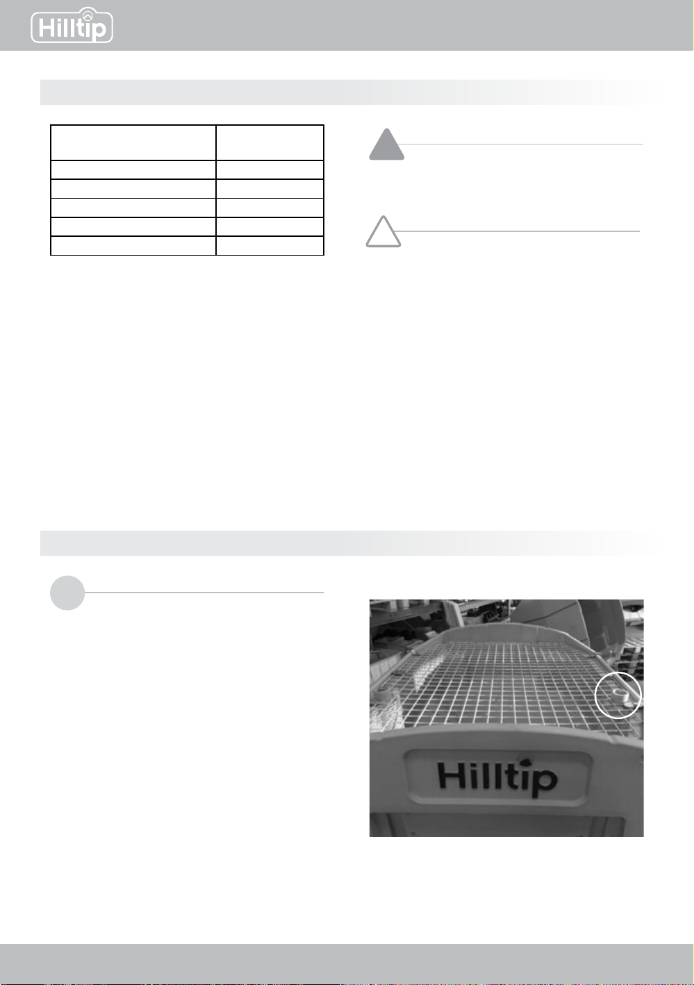
Mounting the top screen
Placethescreensothatittsthehopperopening.
Fasten the brackets on both sides of the screen,
theatbracketshouldbeinthemiddle.

10
IceStrikerTM
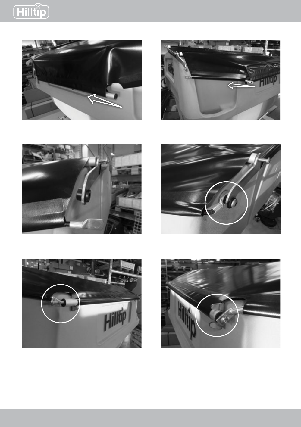
Mounting the Tarp cover assembly
Insert one of the longer pipes into the
opening in the cover (pre-mounted)
1Insert brackets in both sides.
2
Connect pipe and brackets with bolts in
both ends.
3Place the second long pipe under the
cover and connect to the brackets using
bolts
4
11
IceStrikerTM
Insert the short pipe into the cover,
parallel to the other pipes.
5Insert rubber wires into the two
remaining openings in the cover.
6
Connect washer, bracket, bush and
rubber wire with bolt.
8
Place washer and bush around the
bracket, as shown in the picture.
7
Fasten the rubber wire and the shorter
pipe with bolt.
9Fit pipe to the brackets attaching the
screen, and make sure the whole tarp
cover assembly is properly fastened
10

12
IceStrikerTM
Spreading pattern
Rotate the spinner plate to position the material drop point and change spreading pattern.
= material drop point
Drop point in center Spinner plate rotated cw Spinner plate rotated ccw
Rotate jammed auger manually
If the error code “Auger jammed” appears,
the auger can be rotated manually to release
anysolidiedmaterialorrocks.Alwaysturn
othespreaderbeforeservicingit.
Use a 17 mm socket wrench or similar tool
to turn the auger screw.
Rotate auger manually by turning it clockwise
13
IceStrikerTM
LOADING
Material Weight
(kg/m3)
Fine salt - dry 1201
Coarse salt - dry 721
Coarse sand - dry 1602
Coarse sand - wet 1922
Please see your local dealer for proper
vehicle applications.
Only use water or de-icing liquids
for the pre-wetting system
The hopper body has an integrated tank that
should be used only if you had the optional
pre-wetting system included to your spreader
package. Only use liquids recommended in this
manual.
The opening to the integrated pre-wetting tank is
covered by a lid, and located on the side, inside
the hopper body
Average material weights
Filling the integrated pre-wet tank
!WARNING
CAUTION
!
iNOTE
Do not overload your vehicle beyond
GVWR or GAWR, overloading could
result in accident or damage.
These material weights are only
guidelines, for more precise data,
read and adhere to the manufacturer’s
ice-control material package labeling,
including Material Safety Data sheet
requirements.

14
IceStrikerTM
Always close hopper lids to avoid
moisture build-up. Do not let spreader
sit idle with material in the hopper for a
longer time. This could lead to compact
material, reduced or blocked material
owandcausedamagetothehopper.
iNOTE
• Do not operate a damaged
spreader or a spreader in need of
maintenance
• Spreader should be emptied and
cleaned after each use. Left over
material could freeze or solidify in
the hopper causing the spreader
to not work properly.
Power should always be shut
obeforeandduringserviceor
maintenance of the sperader.
Never remove spreader with material
in hopper
Maintaining the spreader
!WARNING
!WARNING
CAUTION
!
Periodical maintenance checklist (check weekly in high-season)
Clean the hopper carefully inside and out with water. Avoid spraying water into bearings, motor
and electrical connections.
Check that all screws and fasteners are tight enough. If you notice any missing or damaged
fasteners or other parts, replace immediately.
Check that all installations and parts are still securely fastened to the spreader assembly.
Apply dielectric grease on all electrical connections.
Lubricategreasettingswithagoodqualitymultipurposegrease.
Yearly maintenance checklist (e.g. before or after putting your spreader away for storage)
Clean the hopper carefully inside and out with water, before putting it in storage. Avoid spraying
water into bearings, motor and electrical connections.
Clean and apply dielectric grease on all electrical plugs and connectors. Clean and install all
dust caps before placing your spreader in storage
Lubricategreasettingswithagoodqualitymultipurposegrease.
Check condition of bearings, replace if needed.
Cover the spreader with a tarp during storage, to protect it from sun fading and other weather
conditions and circumstances.
You must follow all the steps in these
maintenance checklists for warranty
to be valid.
iNOTE
MAINTENANCE
15
IceStrikerTM
Applytotheserecommendationsbeforeplacingyourspreaderino-seasonstoragetomaintainit
in a good condition.
• Cover your spreader using a tarp during storage periods
• Apply a protective compound such as dielectric grease on all electrical connectors and use caps
for protection before storage.
• Disconnect and remove the control unit from your vehicle. Store it in a dry and cool place, and
protect it from heat and moisture.
• Empty the hopper, remove all kinds of debris and clean the hopper from dirt before storage.
• Protect the hopper from excessive heat during storage periods.
Storage
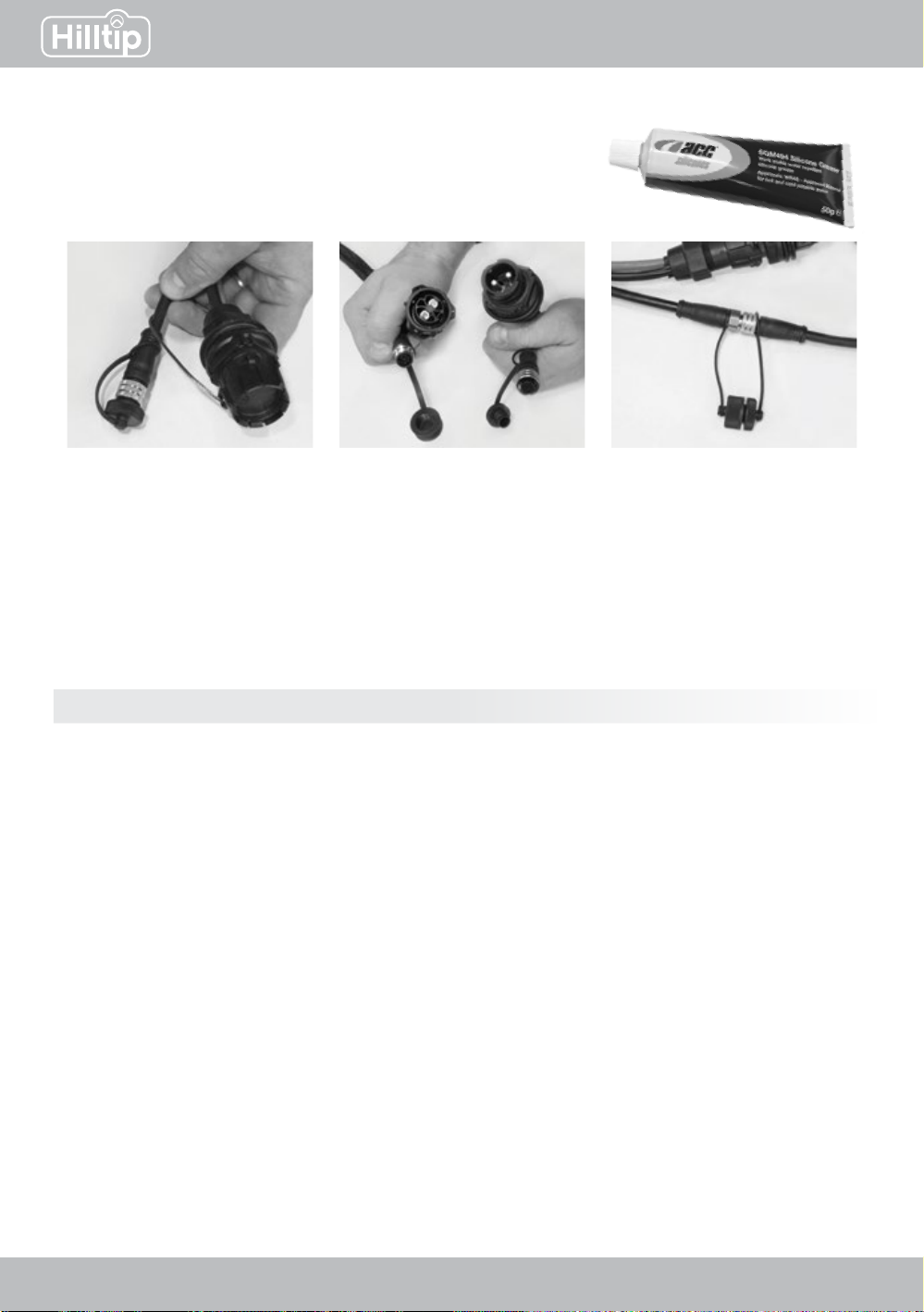
IMPORTANT:
It is strongly recommended and of great importance that you
regularly apply dielectric grease on all electrical connections
and protect them with caps when not in use to prevent corrosion.
Always keep caps on when
the cables are not connected
or in use.
To prevent corrosion, use
dielectric grease on electrical
connectors before connecting
them.
While cables are connected,
also connect matching caps to
protect them from dirt and dust.

16
IceStrikerTM
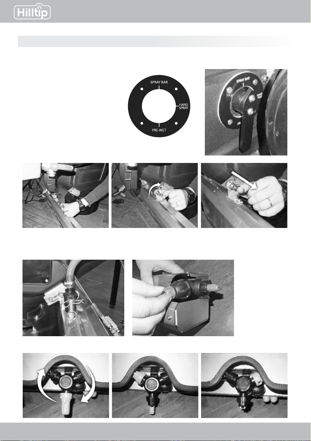
Pre-wet (optional)
2.Youwillndahandleontheright
side of the chute. Point the handle
towards PRE-WET
1. Start with selecting PRE-WET as spreading mode in the controller.
Go to: Main menu > Settings > Wetting > select Pre-wet
The liquid tank should always be emptied after each use (turn
theredhandle).Alsoemptythelter.Ifliquidsareleftinthe
tank for an extended period of time, it may freeze and cause
damage to your spreader.
Alsomakesuretocleanthelterregularly.
Caution!
OPTIONAL LIQUID SYSTEMS
17
IceStrikerTM
Spray-bar (optional)
1. Start with selecting Spray-bar as spreading mode in the controller.
Go to: Main menu > Settings > Wetting > select Spray-bar
2.Youwillndahandleonthe
right side of the chute. Point the
handle towards SPRAY BAR
4. Attach hose to the spray bar and
fasten the cotter pins on both sides
3. Attach spray-bar to the chute:
6. Turn nozzle to change nozzle type:
5.Turntheredcaptoturnontheliquidowtotheside
nozzles (will increase the spray width with 1-1,5 m on
each side)
Quick-disconnect point
18
IceStrikerTM
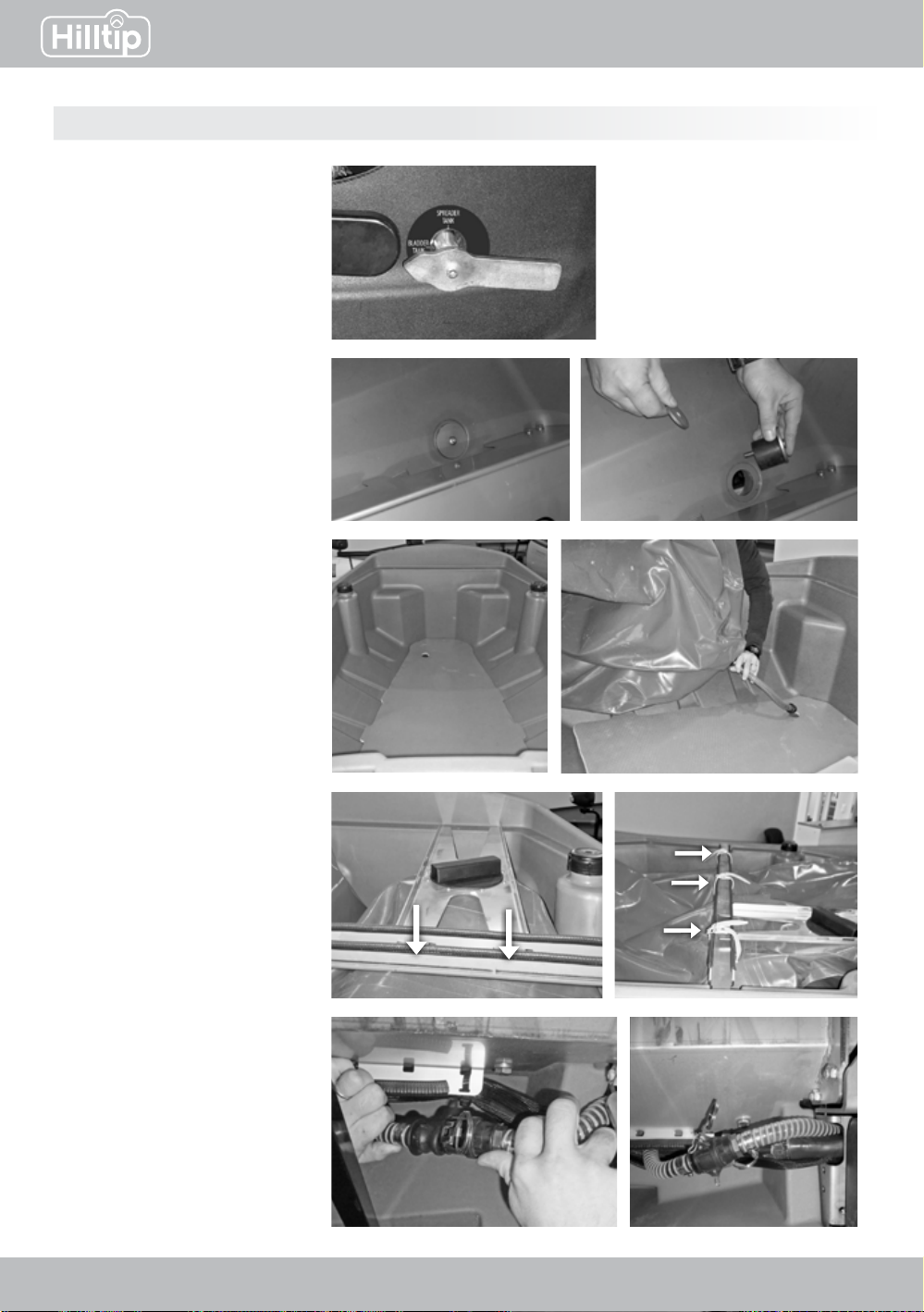
Bladder tank (optional)
2. Remove the plug from
the bottom of the spreader
1.Youwillndahandleon
the left side of the chute.
Point the handle towards
BLADDER TANK
3. Place the bottom support
plate and bladder tank.
Pull the hose trough the hole
of the plate and the hopper.
4. Place and fasten the metal
bars on top of the hopper,
strap the bladder tank to the
bar.
5. Fasten the hose from the
bladder tank to the spreader
liquid system (under the
hopper)
19
IceStrikerTM
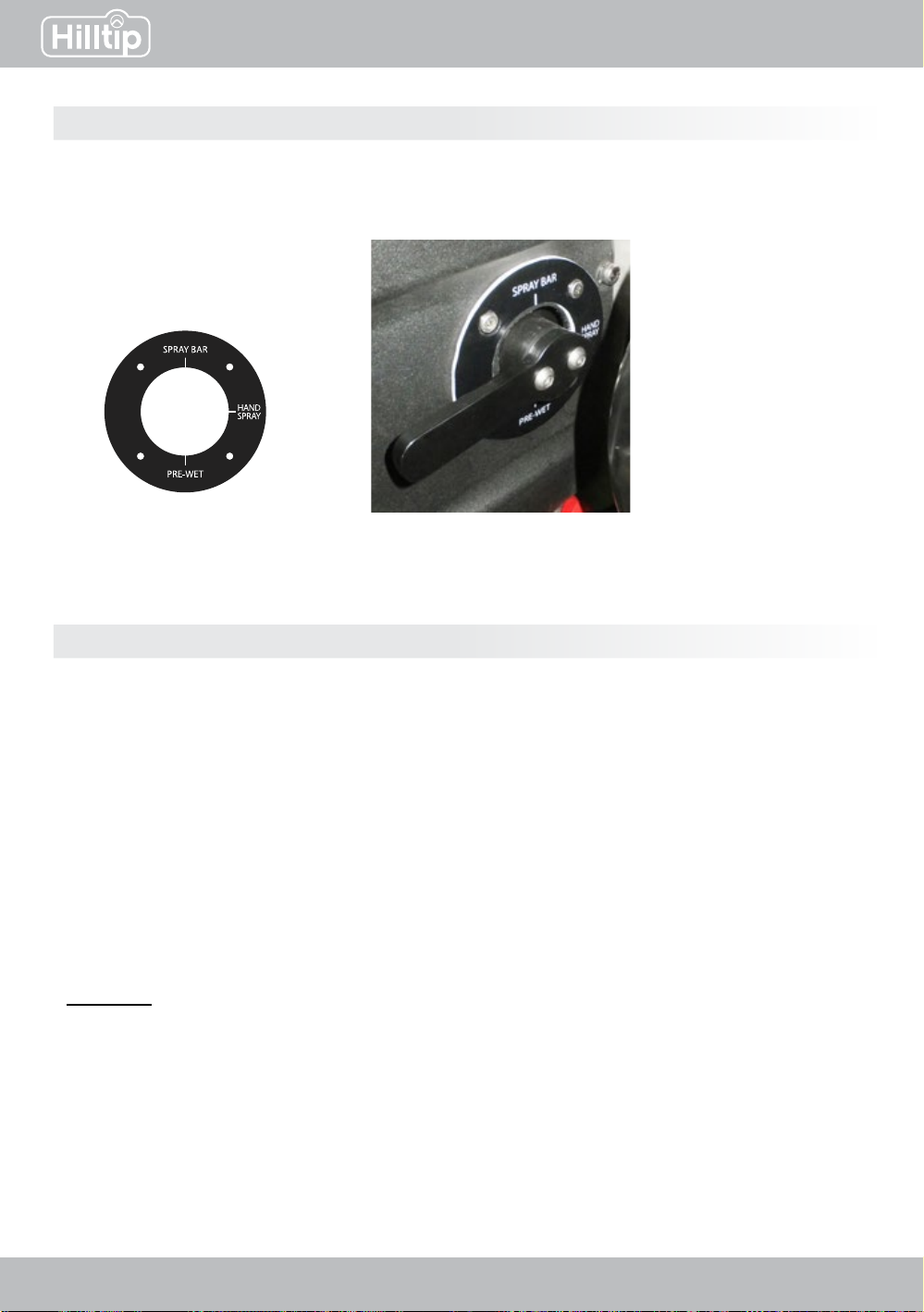
Hose reel (optional)
1. Start with selecting Hand spray as spreading mode in the controller.
Go to: Main menu > Settings > Wetting > select Hand spray
2.Youwillndahandleonthe
right side of the chute. Point the
handle towards HAND SPRAY
IMPORTANT!
Liquid system clean-out instructions
1. Disconnect spraybar hose at rear of vehicle at Quick-disconnect point. (see page 17)
2. Turn on pump until the hopper tank is empty (alternatively pump the salt liquid back into your
storagetank).Onceempty,turnothepump.
3. Disassemblethelter.
4. Connect andpresstheclean-outhoseinstalledwithconeintopumpinletinsidelterhosing.
5. Add water and RV antifreeze into a barrel, where you put the other end of the clean-out hose.
6. Turn on pump.
7. Reinstall quick-disconnect hose to hosereel/spraybar.
8. Run pump until it is running clear out of each nozzle.
Attention! Ignoring these important steps may cause damage to the pump and the entire liquid
system. If damage is caused by avoiding these steps, the warranty will no longer be valid.
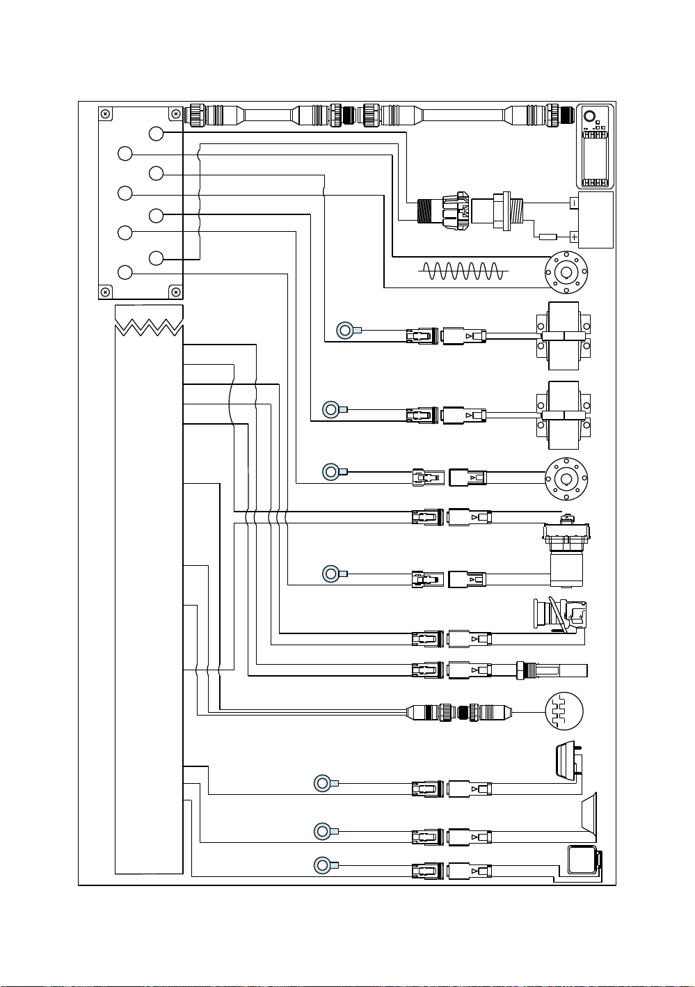
1 2 3 4 5 6 7 8 9 10 11 12 13 14 15 16 17 18 19 20 21 22 23 24 25 26 27 28
Spreader module,
Main connector 35pin
Electrical schematics - IceStriker 600-1000 TR
Liquid
Pump Spinner Auger - Auger +
+12VDC Vibr 1 Vibr 2 GND
35
Battery
FUSE
80A
1
1
2
2
Esc
Auger
Motor
Vibrator 1
12
Spinner
Motor
12
21 21
Liquid Pump
(optional equipment)
1
1
2
2
12
21
Worklight Beacon
Camera +
Transmitter
+12V
Auger-
encoder
Auger-
encoder A/B
Level
sensor Emergency
Stop
1
1
2
2
1
1
2
2
1
1
2
2
1
1
2
2
1
1
2
2
white
black
brown
GND GND GND GND
Vibrator 2
(optional equipment)
12
21
GND GND
GND
This manual suits for next models
2
Table of contents
Popular Spreader manuals by other brands

SnowEx
SnowEx HELIXX installation instructions

Land Pride
Land Pride PS25120 Operator's manual

Durapac
Durapac DHS-05 instruction manual

Teagle
Teagle TITAN 6 Instruction book / parts list

Art's Way
Art's Way V180 Operator's manual and parts list

Fisher Engineering
Fisher Engineering TEMPEST S150A installation instructions

PERFORMANCE ADVANTAGE COMPANY
PERFORMANCE ADVANTAGE COMPANY K5026-JL installation instructions

SnowEx
SnowEx SP-575V Owner's/operator's manual

Wolf Garten
Wolf Garten WE-B Original manual

KUHN
KUHN ALTOR 6070 Operator's manual

Kubota
Kubota VS220-330 Technical & service manual

Gardol
Gardol GST-E 451 Original operating instructions


