1
Important Safety Information
4/03/14 PS25120 Primary Seeder 313-156M
Table of Contents
Important Safety Information
▲
These are common practices that may or may not be applicable to the products described in
this manual.
Safety at All Times
Thoroughly read and understand
the instructions given in this
manual before operation. Refer to
the “Safety Label” section, read all
instructions noted on them.
Do not allow anyone to operate
this equipment who has not fully
read and comprehended this
manual and who has not been
properly trained in the safe
operation of the equipment.
▲The operator must not use drugs
or alcohol as they can change the
alertness or coordination of that
personwhileoperating equipment.
The operator should, if taking
over-the-counter drugs, seek
medical advice on whether he/she
can safely operate the equipment.
▲Operator should be familiar with all
functions of the unit.
▲Operate controls from the driver’s
seat only. Never operate controls
from the ground.
▲Make sure all guards and shields
are in place and secured before
operating implement.
▲Keep all bystanders away from
equipment and work area.
▲Do not leave tractor or implement
unattended with engine running.
▲Dismounting from a moving tractor
can cause serious injury or death.
▲Do not allow anyone to stand
between tractor and implement
while backing up to implement.
▲Keep hands, feet, and clothing
away from power-driven parts.
▲Watch out for fences, trees, rocks,
wires, etc., while operating and
transporting implement.
▲Turning tractor too tight may cause
hitched machinery to ride up on
wheels. This could result in injury
or equipment damage.
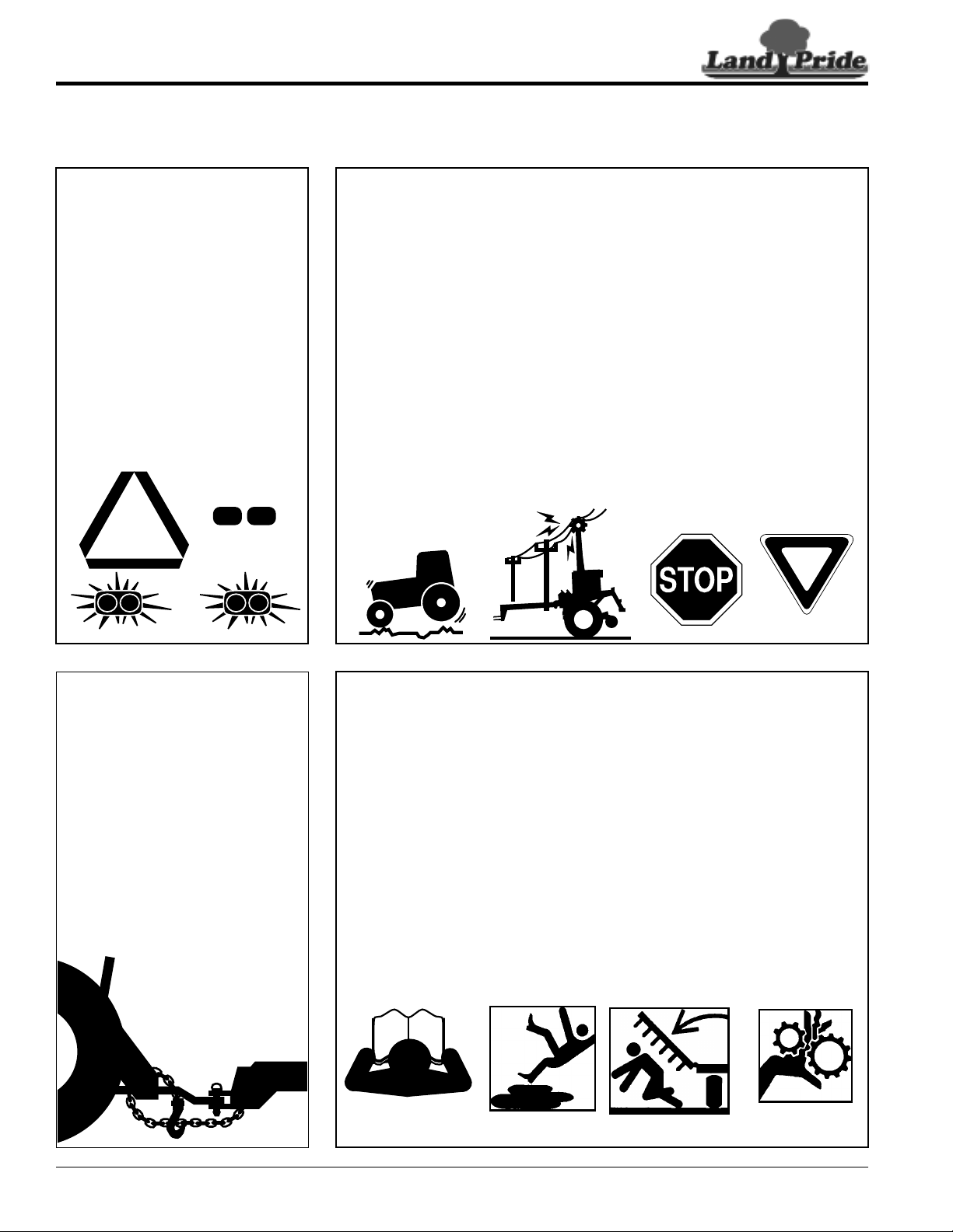
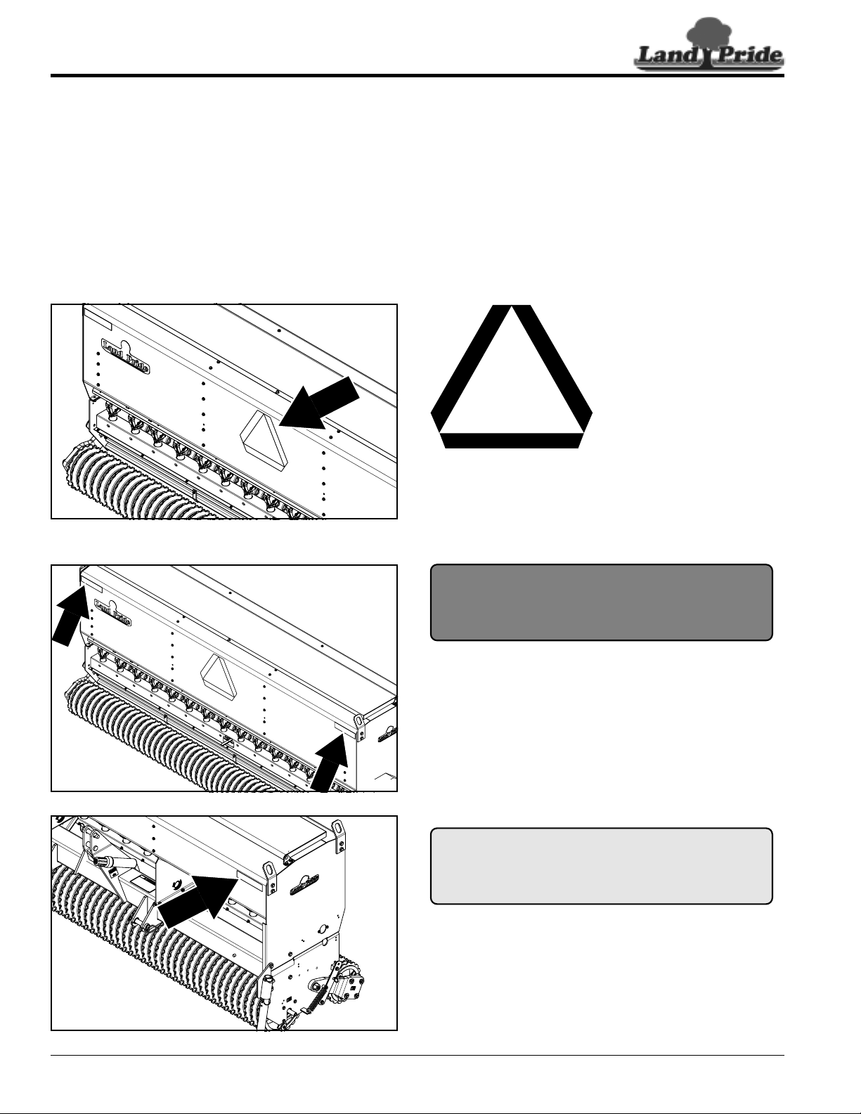
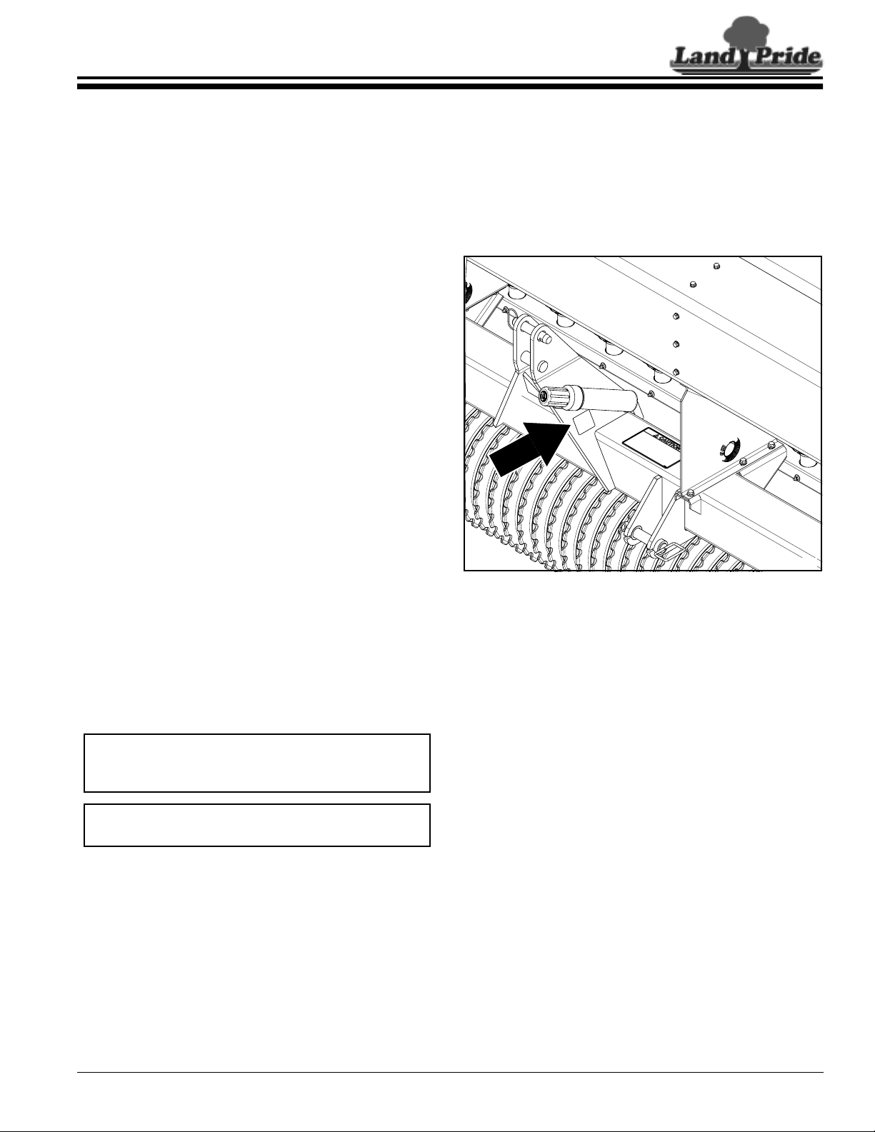
Look For The Safety Alert Symbol
The SAFETY ALERT SYMBOL indicates there is a
potential hazard to personal safety involved and extra
safety precaution must be taken. When you see this
symbol, be alert and carefully read the message that
follows it. In addition to design and configuration of
equipment, hazard control, and accident prevention are
dependent upon the awareness, concern, prudence, and
proper training of personnel involved in the operation,
transport, maintenance, and storage of equipment.
!
Shutdown and Storage
▲Lower attached implement to
ground, put tractor in park, turn
off engine, and remove the key.
▲Detach and store implements in
an area where children normally
do not play. Secure implement by
using blocks and supports.
OFF
REMOVE
Parts Manual QR Locator
The QR (Quick Reference) code on the
cover and to the left will take you to the
Parts Manual for this equipment.
Download the appropriate App on your
smart phone, open the App, point your
phone on the QR code and take a picture.
Dealer QR Locator
The QR code on the left will
link you to available dealers
for Land Pride products.
Refer to Parts Manual QR
Locator on this page for
detailed instructions.
Be Aware of
Signal Words
A Signal word designates a degree or
level of hazard seriousness. The
signal words are:
Indicates an imminently hazardous
situation which, if not avoided, will
result in death or serious injury. This
signal word is limited to the most
extreme situations, typically for
machine components that, for
functional purposes, cannot be
guarded.
!
DANGER
Indicates a potentially hazardous
situation which, if not avoided, could
result in death or serious injury, and
includes hazards that are exposed
when guards are removed. It may also
be used to alert against unsafe
practices.
Indicates a potentially hazardous
situation which, if not avoided, may
result in minor or moderate injury. It
may also be used to alert against
unsafe practices.
!
WARNING
!
CAUTION
For Your Protection
▲Thoroughly read and understand
the “Safety Label” section, read
all instructions noted on them.