Metal-Fach N 267 Installer manual

16-100 SOKÓŁKA, POLAND UL. KRESOWA 62
OPERATING INSTRUCTIONS
PARTS CATALOGUE
MANURE SPREADER
N 267, N 267/1
Edition no. 03
Year of issue: 2010
The original operating manual language is Polish.

2
CE DECLARATION OF CONFORMITY
FOR THE MACHINE
METAL-FACH Sp. z o. o.
ul. Kresowa 62
16-100 SOKÓŁKA
which acts as the manufacturer
declares under sole responsibility that the following machine:
this declaration concerns, meets the following requirements:
- Directive 2006/42/EC OF THE EUROPEAN PARLIAMENT AND OF THE COUNCIL
dated 17 May 2006 on machines, and amending Directive 95/16/EC (OJ EU L157 of
09/06/2006, p. 24) and the Resolution of the Minister of Economy of 21 October 2008
concerning general requirements for machinery (Journal of Laws, no. 199 item 1228).
The following harmonised standards were used for compliance evaluation:
PN-EN 690+A1:2009 PN-EN ISO 4254-1:2009
PN-EN ISO 4254-1: 2009/AC:2010 PN-EN ISO 12100:2011
PN-EN ISO 13857:2010 PN-ISO 11684:1998
- and the following standards: PN-ISO 3600:1998, PN-ISO 11684:1998; and the Resolution of
the Ministry of Infrastructure of 31 December 2002 on technical requirements for vehicles
and the scope of their necessary equipment (Journal of Laws no. 32 item 262 as amended).
Safe Use Test Report No. MF/4/2012
Person responsible for engineering documentation: Marcin Halicki
This Declaration of Conformity becomes void and null if the machine design is
changed or modied in any manner without prior consent from the manufacturer.
Sokółka, 05.11.2012 President of the Management Board
Jacek Marek Kucharewicz
Manure spreader
type/model: N 267-..................................
year of manufacture: ......................................
serial number: .................................................

3
CONTENTS:
TABLE OF CONTENTS
1. INTRODUCTION ....................................................................................................................... 4
2. SAFETY INSTRUCTIONS ........................................................................................................ 5
2.1. RESIDUAL RISKS................................................................................................................... 6
2.2. NOISE AND VIBRATION....................................................................................................... 7
3. INFORMATION AND WARNING SIGNS ............................................................................... 7
4. INTENDED USE ....................................................................................................................... 10
5. OPERATION OF SPREADERS ...............................................................................................11
5.1. Coupling the spreader with the tractor.....................................................................................11
5.1.1. Adapter drive .................................................................................................................. 12
5.1.2. Commissioning and running-in ...................................................................................... 13
5.2. Electrical system ..................................................................................................................... 13
5.3. Loading and unloading ........................................................................................................... 13
5.4. Description of the hydraulic system ....................................................................................... 14
5.5. Hydraulic drive of the oor conveyor..................................................................................... 14
5.6. Adjustment of conveyor chain tension ................................................................................... 16
5.7. Spreading adapter.................................................................................................................... 17
5.8. Brakes adjustment................................................................................................................... 18
5.8.1. Parking brake adjustment............................................................................................... 18
5.8.2. Service brake adjustment................................................................................................ 18
5.9. Adjustment of the land wheels clearance................................................................................ 19
6. MAINTENANCE AND SERVICING ...................................................................................... 20
6.1. Hydraulic system servicing..................................................................................................... 20
6.2. Pneumatic system servicing.................................................................................................... 20
6.3. Periodic maintenance .............................................................................................................. 21
6.4. Lubrication.............................................................................................................................. 21
7. TECHNICAL CHARACTERISTICS ..................................................................................... 23
8. MAINTENANCE, CARE AND STORAGE ........................................................................... 25
9. DISMANTLING, DISPOSAL AND ENVIRONMENTAL PROTECTION ........................ 25
10. EQUIPMENT ............................................................................................................................. 26
11. USE ............................................................................................................................................. 26
12. DESIGN AND OPERATING PRINCIPLE OF THE SPREADER ...................................... 27

4
INFORMATION!
FAILURE TO FOLLOW THE RULES AND GUIDELINES
ICNLUDED IN THESE INSTRUCTIONS MAY RESULT IN DEATH
OR SEVERE BODY INJURY!
1. INTRODUCTION
The user of this product should read and understand these Operating Instructions
in full, as well as follow all the guidelines contained herein to ensure safe operation of
this machine. The Instructions include the description of design and operating principle,
technical characteristics and rules of intended use and servicing of the machine. Exercise
extreme caution when in doubt about any procedure or operation. Should you have any
questions, consult the authorised seller or the manufacturer.
Hazard warning sign
This sign denotes important information on the operating safety, which must be read
in full and relayed to all the service personnel if necessary. The information included in
the Instructions contains the basic guidelines for proper operation and servicing, as well
as about the operating safety and health regulations.
Pursuant to the Regulation of the Ministry of Transportation and Marine Economy issued
on 7 October 1999, no. 91 item 432 included in the Polish Ofcial Journal of Laws no. 32 of 31
December 2002, item 2.6.2. on additional conditions for slow-moving vehicles, we hereby notify
that farming tractors and slow-moving vehicles, as well as trailer units designed for coupling
with these vehicles must feature an identication emblem. The emblems are not required for a
vehicle included in a string of vehicles which is not the last vehicle in the string. We follow this
requirement by equipping our vehicles with special mounting frames which are located on the
spreader adapter guard. Always mount the identication emblem for travelling on public
roads. Place the emblem in the tractor cab when the spreader is on duty.
All manure spreaders conform to the trafc code regulations regarding the trafc of machines
with the maximum speed of 30 km/h on public roads. The machines also conform to the safety
requirements of the valid regulations for the agricultural machines of this type.

5
2. SAFETY INSTRUCTIONS
Always turn off the tractor's engine, remove the ignition key and engage
the parking brake before leaving the driver's seat. Should any failure
occur, always turn off the tractor engine.
Do not turn on the conveyor when the adapter is off. Prior to starting your
work, rst lift the body gate, engage the adapter, run it at the full PTO
speed and then turn on the oor conveyor drive.
Before attempting to work on any systems of the spreader connected to
the tractor with the drive-shaft, turn off the tractor engine and remove
the ignition key. Decouple the drive-shaft before servicing (maintenance,
repairs) the machine. Engage the spreader parking brake and chock the
wheels.
Do not remain in the load body when the drive is on. Do not enter the
spread zone when the spreader is working.
Ensure that no persons remain in the spread zone.
Do not exceed the permissible payload and driving speed, otherwise the
machine may be damaged and the trafc safety may be compromised.
Adapt the driving speed to the conditions when working or travelling on
a rough terrain. Follow the trafc code regulations when travelling on
public roads.
Do not use the oor conveyor to unload such materials as coal, wood, stone
or construction materials.
Do not use the machine on a terrain with an inclination of 8.5 o.
Note that during the unloading the machine will change its impact on the
tractor and its manoeuvring conditions.
Operation of the spreader without the system guards, riding on the
spreader and its tow bar or driving without the connected braking system
is strictly forbidden. The driver's mesh guard must be installed on the
front end of the load body. The upper edge of the mesh guard must be
placed at least 2.6 m from the ground surface. The PTO drive-shaft must
always be equipped with the full guard.
The mesh guard must be positioned to secure the adapter drums when
towing the spreader on public roads. Spreaders equipped with the body
gate can only travel on public roads with the gate closed.

6
The spreader can be operated only by adult personnel with a valid tractor
driving licence. It is strictly forbidden to operate the machine when under
the inuence of alcohol or drugs.
Exercise due caution when performing any disassembly to prevent
personal injury. If your skin is cut, wash the wound thoroughly, disinfect
with medical hydrogen peroxide solution and seek medical attention. Any
wound fouled with manure may result in Tetanus bacteria infection.
2.1. RESIDUAL RISKS
This spreader has been designed and produced in accordance to the state of technology
and safety requirements valid for its year of manufacture.
The manufacturer of this spreader has taken every effort in its design, production
and labelling to eliminate all hazards related to operation, servicing and maintenance.
However, there are specic unavoidable risk present.
Residual risk results from incorrect or improper conduct of the operating personnel.
The greatest hazards occur during the following forbidden actions:
• Operation of the spreader by minors or persons who are unfamiliar with the operating
instructions;
• Operation of the spreader by personnel under the inuence of alcohol or other
intoxicants;
• Performance of any work on the spreader systems, when the spreader is coupled with
the tractor with the running engine;
• Attempting to work with the machine before inspecting the work site and environment;
• Remaining on (aboard) the machine when it is working or in transit;
• Use of PTO drive-shafts without any guards;

7
Follow these guidelines and prohibitions:
• read and fully understand the operating instructions;
• secure the machine against access by unauthorised persons and children;
• cleaning, maintenance and repairs must be performed by adequately trained persons
and with the PTO drive-shaft decoupled;
• keep your hands out of hazardous spaces;
• do not use the machine when it is not t for duty and/or when the guards are missing;
• do not use the PTO drive-shafts without any guards;
• no persons are allowed to remain near the machine when it is working;
• no persons are allowed to remain on the machine when it is working or in transit;
• do not transport the machine without the connected and functioning braking and
lighting systems;
only then can you eliminate the residual risks to people and the environment when
using this spreader.
INFORMATION!
The residual risks are present when the aforementioned rules are not
followed.
2.2. NOISE AND VIBRATION
The operator is inside the tractor cab when the machine is working.
The equivalent sound pressure emission level A (LpA) is 76.0 ± 1 dB.
The peak sound pressure value C (LCpeak) is 86.0 ± 1 dB.
Machine sound power – N/A.
(Measurements acc. to PN-EN ISO 4254-1:2006 Annex B section 2.6)
No vibration hazards occur when working with this machine.
The operator's work station is located in the tractor cab, with shock absorption and an
ergonomically proled seat. The value of the vibration exposure of the operation does not
exceed 0.6 m/s2.
3. INFORMATION AND WARNING SIGNS
Extremely hazardous areas are indicated with the yellow warning signs and warning
labels placed on the machine. During operation of this machine, exercise extreme caution
when remaining in direct proximity of these areas.

8
Check the serial number indicated in the Operating Instructions and the warranty card
against the serial number stamped on the nameplate and the chassis frame. The nameplate
and the stamped serial number are located on the chassis end sill, i.e. on the right side of the
machine.
The warning stickers must always be legible. If the stickers become
illegible, if the assembly on which they are located is replaced or the
machine is repainted, the stickers must be purchased at the retail outlets
or ordered at your local dealer as spare parts and suitably replaced.
Warning! Read the Operating Instructions.
(1x)
Turn off the engine
and remove the ignition key before servicing
or repairs.
(1x)
PTO rotational speed: 540 RPM.
(1x) Do not remain between the machine and the
tractor when the engine is running.
(1x)
Do not approach the working machine.
Maintain a safe distance from the tow bar when
it is being lifted or lowered.
(2x)
Speed limit sign.
(1x)
Air pressure in tyres.
(2x)
NAMEPLATE
Nameplate
(1x)
540 min-1
1
3
5
7
2
4
6
8

9
Lug for lifting hooks
(8x)
Couple with the trailer by using
the single-axle trailer hitch
Warning label.
(1x)
Turn off the PTO drive at road
turns.
Warning label.
(1x)
Do not enter the load body when the
drive is on.
Warning label.
(1x)
Keep a safe distance from power lines
(1x)
Brake release sign.
(1x)
Load capacity: ... t
Information label
(2x)
Company logo.
(2x)
Information label – machine symbol.
(2x)
Weight: .... kg
Description of the adapter weight.
(2x)
Keep a safe distance from the
adapter. Do not put your hands
between the rotors.
(2x)
Warning sign.
(2x)
Ejected objects. Keep a safe distance from the
machine
(2x)
Lubrication point.
(4x)
9
11
13
15
17
19
21
10
12
14
16
18
20
22
10
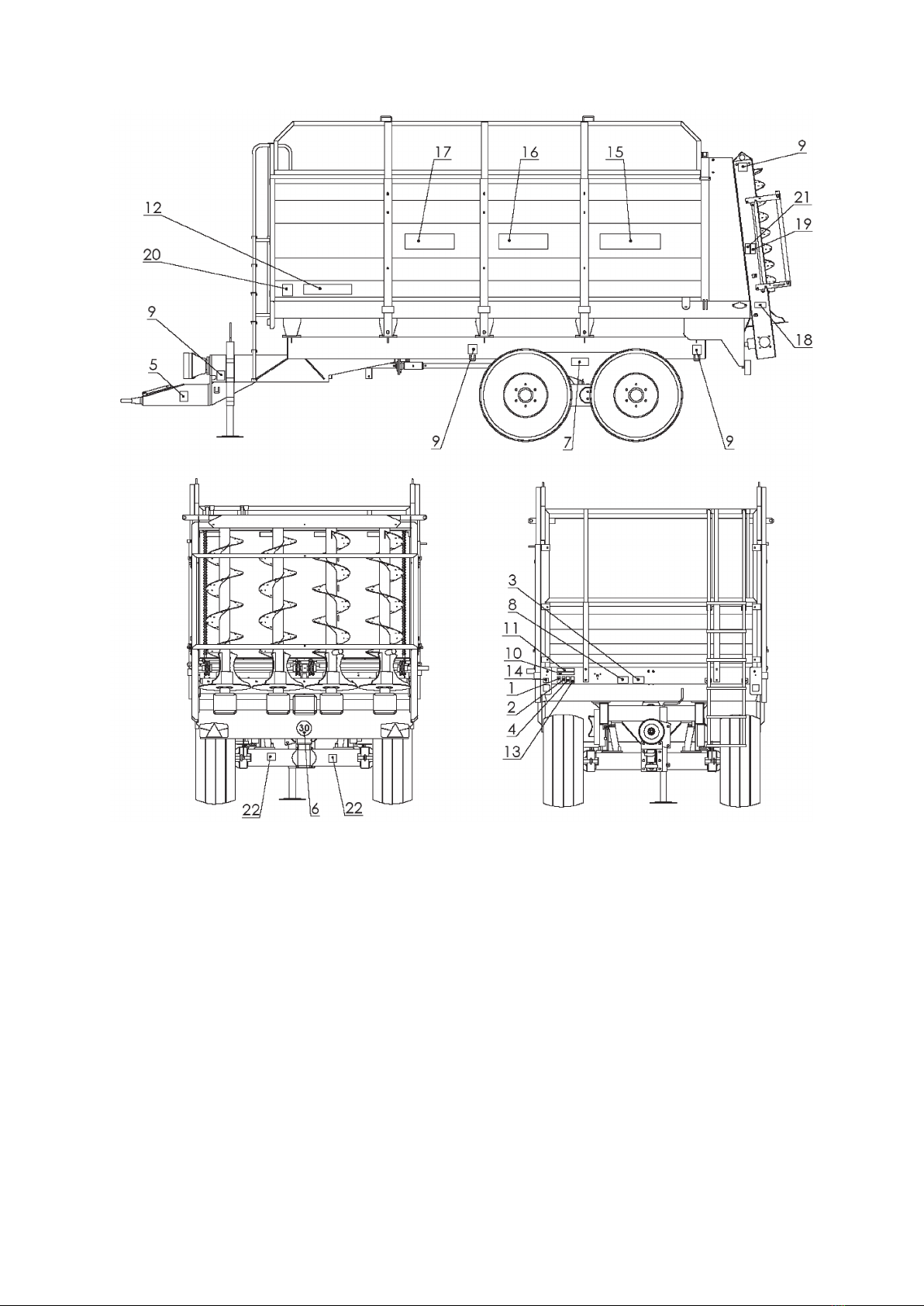
Fig. 1. Locations of the information and warning signs
4. INTENDED USE
• The spreaders are intended for spreading of manure, peat, compost, etc. and transportation
of crops within farms and on public roads. The machines are self-dumping and coupled with
farming tractors only by the lower hitch.
• Spreaders equipped with gates facilitate transport of ne-grained bulk loads by preventing
its spillage from the load body.
• The spreaders can only be operated and serviced by adults who have read and
understood these Operating Instructions, in particular the information in section
"Safety Instructions".

11
• Improper servicing and use of this machine, i.e. not following the Operating Instructions
relieves the manufacturer from any liability for the results of improper use and makes
the warranty void and null.
• The manufacturer forbids any unauthorized modication of the spreader designs. Making
any modications of the design releases the manufacturer from any effects of such
changes and may void the warranty.
• Consult your supplier or the manufacturer's service department in case of any doubts
regarding the use of the spreader.
5. OPERATION OF SPREADERS
5.1. Coupling the spreader with the tractor
The spreader is coupled with the tractor in the following way:
¾attach the spreader tow bar lug to the lower hitch of the tractor;
¾t the PTO drive-shaft and use the chains to prevent the shaft guard against turning during
operation;
¾connect the spreader's electrical system to the tractor's electrical system and secure the plug
against decoupling;
¾connect the spreader's drive hydraulic system to the terminal of the tractor's hydraulic system
by twisting the quick-release coupling's nut clockwise until resistance is felt;
¾connect the pneumatic system of the service brake;
¾connect the body gate's hydraulic system;
¾next, check the tightness of the connection between spreader and the tractor's hitch, check
operation of the electrical system, service brake, systems and drives. If all systems are work
properly, release the parking brake and set the support in the travel position.
THE FOLLOWING IS STRICTLY FORBIDDEN:
� coupling the spreader with the tractor using any other coupling than the lower hitch.
The machine must have the parking brake engaged when it is being coupled;
� to keep the external hydraulic systems of the tractor pressurised when coupling the
trailer – all control valves must be set to neutral. When the quick-release coupling nut
is tightened, the coupling is opened and high oil pressure may result in a leak. Tighten
the nuts until resistance is felt to guarantee tightness;
� loosening the quick-release coupling nuts when the power system and the hydraulic
brake are working.
Disconnecting the spreader
Before disconnecting/decoupling the spreader from the tractor, rst engage the machine
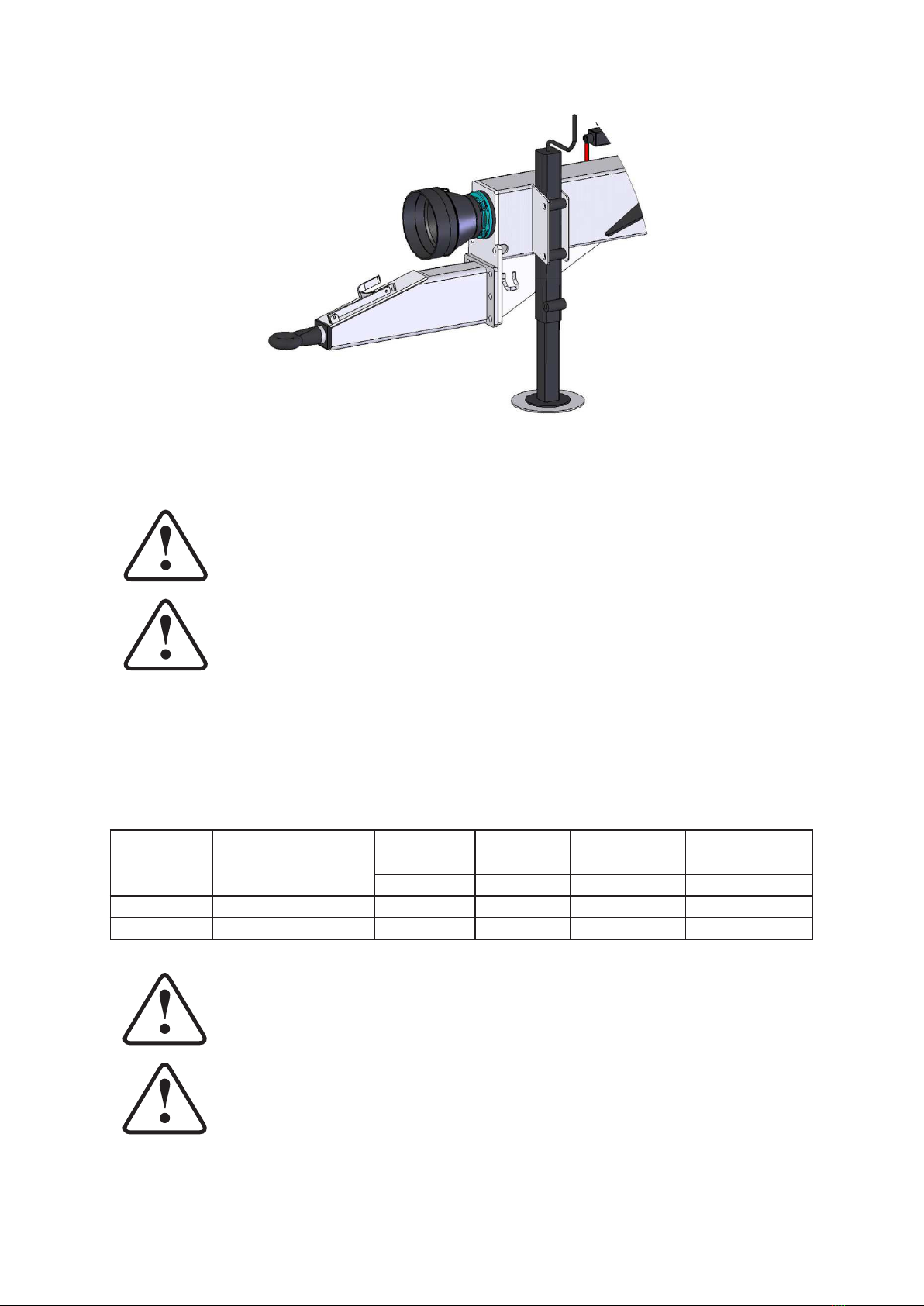
parking brake and lower the support – see g. 2 item 1.
The support stabilizes the spreader whether it is loaded or not.
12
Fig. 2. N267 and N267/1 spreader support
Do not disassemble the support or rest the machine on makeshift supports.
Do not leave agricultural equipment on slopes or any other terrain
inclinations without securing it against accidental rolling.
5.1.1. Adapter drive
The adapter drums are driven by the PTO drive-shaft, which couples the tractor PTO with
the two-sectional drive shaft and the PTO drive-shaft with the friction overload clutch. The
clutch protects the power system against damage when the torque exceeds the factory set value.
The PTO drive-shafts used in the spreader:
Machine
type Shaft designation
Rated
torque
Rated
length
Transferred
output
Overload
clutches
Nm mm kW Nm
N267 6R602-7-BA-K601 540 1745 30 1600
N267/1 8R802-3-DA-C803 900 920 50 1500
The shaft must have the "CE" marking. Use only the shafts that are
equipped with complete guards.
Do not use the PTO drive-shaft with damaged guards.

13
The overload clutch should not engage when the machine is properly operated. If the clutch
engages, the machine is overloaded. If the material is not ejected during operation, the friction
overload clutch is engaged. Eliminate the cause of overload (e.g. a cord wound on the drums,
objects jammed between the drums, i.e. pegs or alike).
Before attempting to clear the jam, turn off the tractor engine and remove
the ignition key. Decouple the PTO drive-shaft from the tractor.
Prior to turning the machine on after elimination of the problem; switch the
shift direction for a short moment directly before turning on the drive. (The
conveyor shift direction is switched by changing the feed direction with the
directional control valve of the tractor.)
5.1.2. Commissioning and running-in
Do the following before commissioning the spreader:
• read and understand the operating instructions in full;
• congure the machine in accordance with the intended work;
• check the tightness of all threaded connections and the tension of chains;
• supply lubricants at the lubrication points;
• check the transmission oil level and add if required – use HIPOL – 15 oil;
• park the spreader and run it in initially without load.
The initial running-in should last approximately 15 minutes at decreased rotational speed
of the tractor drive. During this procedure ensure that all systems work smoothly, without
jamming and excessive noise. Make sure that the fastening bolts did not become loose and
check the chain tension after the initial running-in is nished.
During the rst 20 operating hours, lubricate all lubrication points twice a day. Replace
the transmission oil afterwards and check the tightening of bolts and chain tension. Readjust if
necessary.
5.2. Electrical system
The spreader is equipped with a 12 V electrical system supplied from the tractor. Always
make sure that the lighting system is functional before entering a public road. The electrical
system powers the two front side lamps, the lamp clusters and the clearance lamps.
5.3. Loading and unloading
Manure can be mechanically loaded on the spreader. In order to fully use the spreader's load
capacity when working with long-straw manure, it is allowed to ll the load body up to 10 cm
above the upper edge. Do not load the long-straw manure directly on the adapter drums – this
may damage the drive. The load must not hang over the body sides. When the work is nished
or if needed, remove the manure which may accumulate on the rear beam in the area of socket
wheels and on the spreader drums, as well as on the drive shafts. Excessive accumulation of
dirt can overload the tractor and elongate the conveyor chains. In order to achieve the best

14
spreading parameters (i.e. width and uniformity), keep the PTO speed on the tractor between
470–540 rpm.
REMARKS:
1. After all manure has been spread, turn off the adapter drive and lower the
rear gate.
2. Clean the spreader only when the drive is decoupled and the tractor is stopped.
Exercise extreme caution when cleaning with the raised gate. Decouple the
PTO drive-shaft from the tractor.
3. When the spreader works on the eld, the material in the load body moves
towards its rear end. This slowly decreases the pressure on the tractor hitch
and lowers the wheel grip of the rear tractor wheels. This may reduce the
tractor's pull force on difcult terrain (i.e. hummocky or damp ground). Due
to this fact, it is advised to perform the nal phase of unloading the load body
of the spreader when moving down a slope or on a at (level) terrain.
5.4. Description of the hydraulic system
The spreader is equipped with a single-section or two section hydraulic system.
The hydraulic control in the single-section system is effected by a set of two levers delivered
with the spreader. The levers are to be installed in the tractor cab.
These levers control the two-sectional directional control valve, which is fed directly from
the tractor's system. One of the levers actuates the gate drive, while the other actuates the oor
conveyor drive.
In the two-section hydraulic system, the hydraulic lines of the gate and conveyor drives are
connected directly to the tractor. The control is effected directly from the cab by actuation of
corresponding hydraulic output sections of the tractor.
5.5. Hydraulic drive of the oor conveyor
The oor conveyor system of the spreader is hydraulically driven by the transmission
gearbox powered from the hydraulic motor, which in turn is driven by the hydraulic system of
the tractor.
The shift speed of the oor conveyor (i.e. the manure spreading output) is controlled and
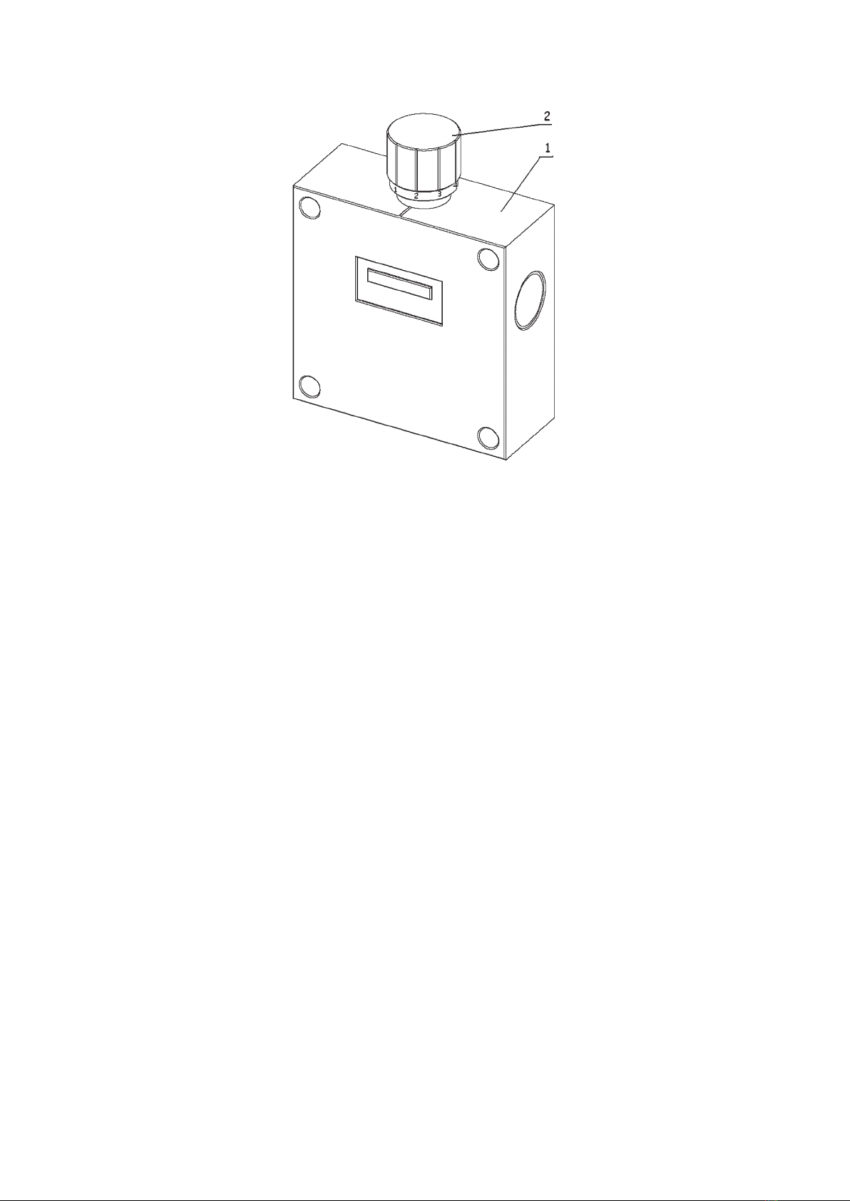
adjustable by setting the adjustment screw (2) of the ow controller (1) installed in the right
section of the spreader front panel. Turning the adjustment screw clockwise increases the
conveyor shift speed, while turning it counter-clockwise decreases the shift speed. When the
spreader is unloaded and the material mass decreases, the conveyor shift speed slightly increases
at the same time.
15
Fig. 3. Flow controller
Only the reverse shift speed of the conveyor is pre-set. Switching the conveyor shift to
forward motion is done by changing the feeding direction in the tractor (with the directional
control valve of the tractor) when the valve at the ow controller is open.

16
Optional accessories include an user-installed adapter kit that enables coupling with a single
hydraulic section of the tractor. The gate and the oor conveyor are simultaneously controlled
by a DCV attached to the spreader and controlled from inside of the cabin with Bowden cables.
To install the adapter kit:
1. Open the 4 hydraulic lines that couple the tractor with the spreader.
2. Screw the cable-actuated DCV (included with the kit) to the spreader.
3 Install a two-position catch (included with the kit) on the right hand spreader section that
controls the oor conveyor drive.
4. Connect the Bowden cables to the DCV.
5 Connect the 2 hydraulic lines between the DCV and the tractor (the inputs are at the DCV
sides).
6. Connect 4 hydraulic lines with the DCV section outputs (the lines which are connected
with the gate's steel lines on the spreader left hand side and with the conveyor speed
controller unit on the right hand side).
When in doubt, consult the spreader single-section hydraulic system diagram in the Spare
Parts Catalogue.
The design manure feed rate at the tractor PTO rotational speed of 540 rpm and the hydraulic
system pressure of 13 MPa can be innitely variably adjusted from 0.2 to 1.3 m/min.
Note: Take extra caution when performing the adjustment. Turn off the
tractor engine, remove the ignition key and engage the parking brake of
the tractor.
5.6. Adjustment of conveyor chain tension
The conveyor chains are adjusted by the stretcher screws (see g. 4 item 1) located on the
front panel of the spreader. The tension of the chains is veried by lifting the chain at the middle
of the body oor length. The distance of the chain from the oor should be 1–6 cm when lifted.
If the chain is stretched beyond the maximum adjustment value, replace the chain.
17
Fig. 4. Tensioning the conveyor chains
Adjust with the screws (1). When the chain is tensioned with the screws (1), lock the chain
stretcher bodies by tightening the bolts (2) and securing them with locknuts.
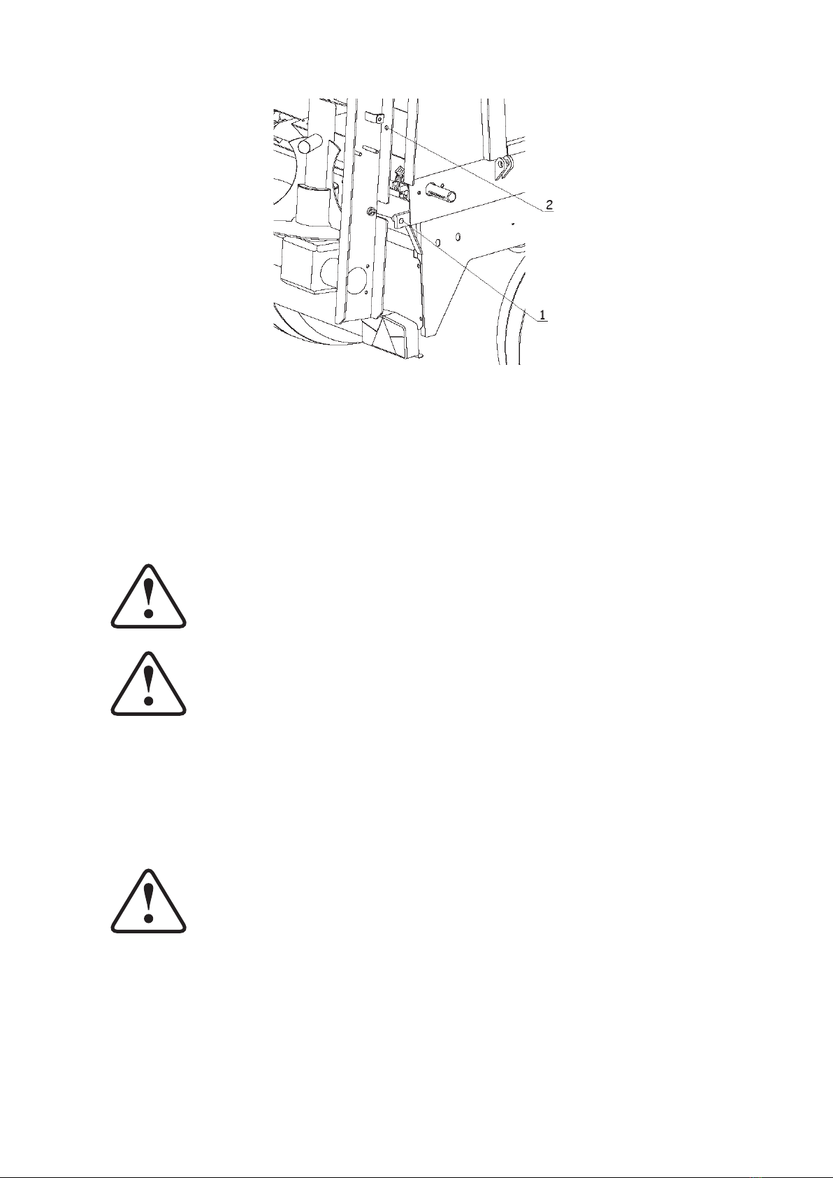
5.7. Spreading adapter
The adapter consists of a frame which houses four worm drums driven by the PTO drive-
shaft, the drive shafts and the transmission gearbox. The drive is transmitted from the tractor's
PTO.
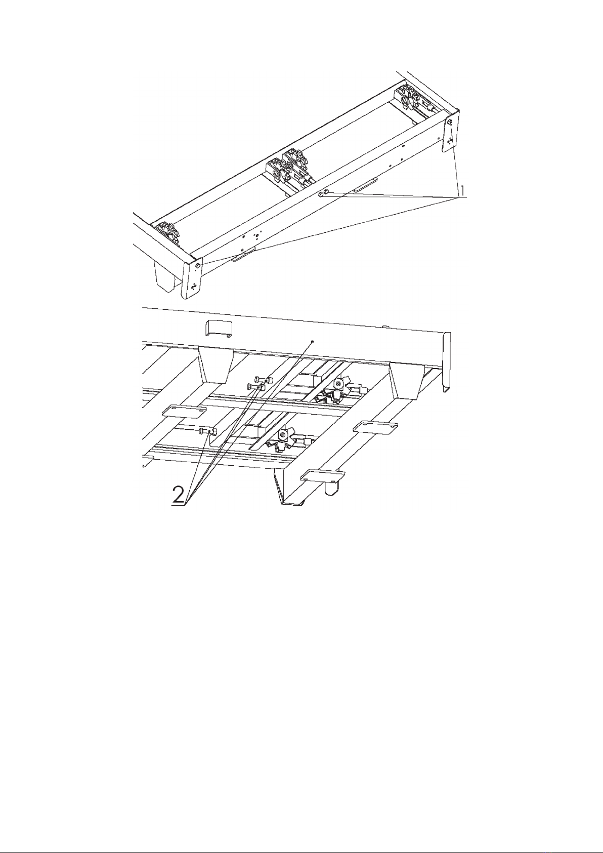
The adapter frame is connected to the spreader chassis with two pins set in the bottom frame
grips (see g. 5 item 1) and fastened to the load body with the bolts (see g. 5 item 2).
18
Fig. 5. Adapter mounting
Adapter disassembly procedure:
• Decouple the PTO drive-shaft from the adapter transmission.
• Remove the fastening bolts which attach the adapter to the side panels and remove the
adapter.
• Use a lifting device with the minimum capacity of 600 kg to remove the adapter.
Exercise extreme caution when assembling and disassembling (repairing)
the adapter. Due to the large weight of these components, use suitable lifting
equipment. The assembly and disassembly procedures must be performed
by two persons.
The vertical adapters and the attachment must be handled with the use of
a lifting device with the minimum capacity of 600 kg.
5.8. Brakes adjustment
5.8.1. Parking brake adjustment
The parking brake is adjusted by setting the initial cable tension by making a loop of a
suitable length on both cable ends.
The parking brake is functioning when it is capable of stopping the loaded
spreader on a slope with a grade of 18°.
5.8.2. Service brake adjustment
The braking system must be suitably adjusted to compensate the wear of the brake shoe
linings. If the actuator idle stroke is excessive, adjust as follows:
remove the cotter pin (3), remove the crown nut (1), loosen the brake expander lever (2) and
shift the lever in the direction opposite to the braking motion in such way that the lever is
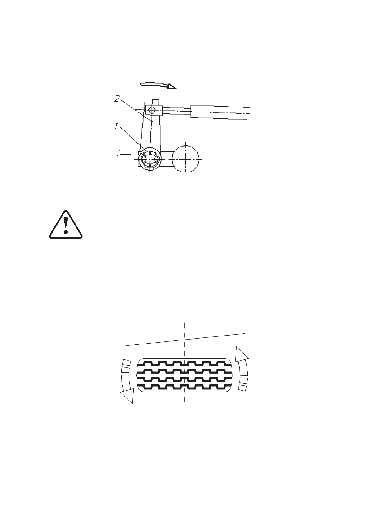
19
perpendicular to the brake actuator when the latter is in the braking position. If the brake
linings are excessively worn, replace them. After each adjustment make sure to tighten the
crown nut and secure it with a new cotter pin.
Fig. 6. Main brake adjustment
When the brakes are properly adjusted, the spreading unit (tractor +
spreader) with the rated load at 30 km/h should stop at 10 m from the brake
engagement and the wheels should brake uniformly.
When the spreader has made the rst 100 km, check the brakes and adjust them if
necessary.
5.9. Adjustment of the land wheels clearance
When the new spreader has made the rst 100 km and every next 1000-1500 km, check the
clearance of the land wheels and adjust it if necessary.
Fig. 7. Checking the clearance of the land wheels
Check the clearance of the land wheels as follows:
Couple the spreader with the tractor on the lower hitch and engage the tractor parking brake.
Jack up one side of the spreader to lift the wheel from the ground on this side and secure the
spreader against falling. Attempt to turn the wheel in order to check the bearing clearance, see

20
Fig. 8. If the wheel clearance is too large, remove the hub cap, remove the cap seal and the crown
nut clevis pin. Rotate the wheel and tighten the crown nut at the same time until the wheel stops.
Now loosen the crown nut by 1/6-1/5 of the full turn, i.e. to the nearest clevis pin groove. Install
a new clevis pin, new seal and mount the hub cap. Repeat for the other spreader wheels.
6. MAINTENANCE AND SERVICING
6.1. Hydraulic system servicing
The hydraulic system oil of the spreader and the external hydraulic system oil (tractor) must
always be of the same grade.
DO NOT use different oil grades. The system has the SAE 80W viscosity
oil.
Caution! The hydraulic hoses must be replaced after 6 years from the date
of manufacture.
Caution! The supply (feed) lines are identied with a yellow strap.
The spreader hydraulic system must be absolutely leak-tight. If there are oil leaks at the
hydraulic connections, tighten them; if the leak persists, replace the hose or the connection
ttings. The hydraulic hoses must also be replaced upon any mechanical damage.
The condition of the hydraulic system must be monitored continuously throughout the
operating life.
Caution! The hydraulic oil must be replaced in accordance with the
operating manual of the coupled tractor, but at least every two years.
This manual suits for next models
1
Table of contents
Other Metal-Fach Spreader manuals


Popular Spreader manuals by other brands


Tube-Line
Tube-Line Nitro 450 Operator's manual

Earth Way
Earth Way M20 Assembly instructions

Gearmore
Gearmore RE100 Operation, service & parts manual

AMAZONEN-Werke
AMAZONEN-Werke EK-S 150 Operation manual

Scotts
Scotts AccuGreen 3000 manual

Meyer
Meyer Blaster 350 Installation instructions and owner's manual