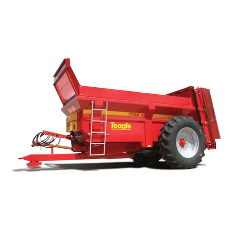
Teagle TITAN 6 User manual

- -
_ _ _ _ _ _ _ _ _ _ _ _

SAFETY FIRST!
1. READ THE INSTRUCTION BOOK THOROUGHLY
before attempting to operate or carry out any
maintenance on the machine. If you do not
understand any part of this manual, ask your dealer
for assistance.
2. ALWAYS CARRY OUT SAFE
MAINTENANCE. Never clean, adjust or
maintain the machine until the engine has been
stopped, the machine come to rest, the PTO
disengaged and the key removed.
3. NEVER WORK UNDER A MACHINE OR
COMPONENT SUPPORTED
HYDRAULICALLY unless it is securely
supported.
4. NEVER OPERATE THE MACHINE WITH ANY
PARTS OR GUARDS MISSING. Check that all
guards including the PTO shaft guards are in good
condition and in place before operating the machine.
5 OPERATE SAFELY. Before starting work, check
that there are no persons or animals in the
immediate vicinity of the machine or tractor. Always
maintain full control of the tractor and machine.
Ensure that you know how to stop the tractor and
machine quickly in case of emergency.
6.SECURE THE PTO GUARD BY MEANS OF
CHECK CHAINS to suitable points on the tractor
and machine to prevent the outer plastic shield from
rotating.
7. NEVER STAND BETWEEN THE MACHINE AND
THE TRACTOR WHEELS.
8. DO NOT WEAR LOOSE OR RAGGED CLOTHING
9. BEWARE OF DISEASE RISKS. Use protective
clothing or overalls and wash both hands and
overalls thoroughly immediately after work. Wash
the machine if necessary before carrying out
maintenance operations.
10. BEWARE OF HIGH NOISE LEVELS. Some
tractor/implement combinations give noise
levels in excess of 90dB at the operator's ear.
Under such circumstances, ear defenders
should be worn. Keep cab windows and doors
closed to reduce noise level.
Throughout this handbook, the term `tractor' is used to
refer to the power source used to drive the machine. It
does not necessarily refer to a conventional agricultural
tractor.
HEALTH AND SAFETY AT WORK
Our equipment is designed so as to conform with
current Health & Safety Regulations and therefore
poses no significant hazard to health when properly
used. Nevertheless, in the interests of all concerned, it
is essential that equipment of our manufacture is used
in accordance with the instructions that are supplied or
are available from our Technical Staff.
Legislation requires that all operators are instructed in
the safe operation, cleaning and maintenance of
equipment and machines. This handbook forms part of
that instruction and it must be read and understood
before fitting the machine onto the tractor or attempting
to use it.
Your supplier is responsible for carrying out any
necessary pre-delivery inspection, fitting the machine
onto the tractor and test running. The supplier must
also give instruction in the safe use, maintenance and
adjustment of the machine.
In the interests of safety, please ensure that the
instructions referred to above are brought to the
attention of all your employees who are to use the
equipment. We recommend that the use of this
equipment is restricted to capable trained operatives.
Persons under the age of sixteen should not operate the
machine and should be kept away from where it is being
used.
WARRANTY
The standard warranty is for 12 calendar months against
faulty materials and workmanship. Components supplied
as part of the original machine, but manufactured by
another company, e.g. PTO shafts, wheels etc., are subject
to the original manufacturer's conditions and warranty.
Where repairs are carried out under warranty:-
a) Claims for the fitting of non original parts will not be
considered unless prior agreement has been obtained.
b) The repairer must be advised that the work is to be the
subject of a warranty claim beforehand.
c) Any claim must be submitted within four weeks of the
repair.
d) The damaged parts must be retained for inspection and
returned carriage paid if required.
The right to withdraw warranty is reserved if:-
a) Non-original parts are fitted.
b) The machine has been abused, badly maintained or
used for purposes other than that for which it was
designed.

EC Declaration of Conformity
conforming to EEC Directive 2006/42/EC
Teagle Machinery Ltd.
Blackwater
Truro
Cornwall
TR4 8HQ
United Kingdom
declares in sole responsibility that the
TITAN 6, TITAN 8 And TITAN 9
Rear Discharge Muck Spreader
to which this certificate applies
conforms to the essential Health and Safety requirements of
EEC Directive 2006/42/EC & 2004/108/EC.
To effect correct application of the essential
Health and Safety requirements stated in
the EEC Directives, the following harmonised standards were consulted:
BS EN ISO 12100-1
BS EN ISO 12100-2
BS EN ISO 13857:2008
BS EN 690
Signed:
Duncan Wilson (Engineering Director)
Dated: 06th February, 2013
Person authorised to compile Technical File
Duncan Wilson,
Teagle Machinery
Blackwater,
Truro
Cornwall
TR4 8HQ
United Kingdom
Machine Serial No. . . . . . . . . .

INSTRUCTIONS
Specifications 2
Explanation of pictograms 2
Safety 3
Left & right hand 3
Identification numbers 3
Preparation of the tractor 3
Fitting the machine on to the tractor 3
Operation
Winter 3 - 4
Loading 4
Starting to spread 4
During spreading 4 - 5
Stopping spreading 5
Maintenance
Cleaning and storage 5
General 5
Oil levels 5
Bed conveyor 5 - 6
Beaters 6
PTO driveline 6
Axles, wheels and tyres 6
Service brakes 7
Handbrake 7
Transportation 7
Lubrication
Grease 7
Oil 7
Gearboxes 7
FAULT FINDING CHART 8
PARTS LIST
Wheels and axle components 9 - 10
Decals 10
TVZ Assali axle components 11
Manual bed speed control 12
Bed components 13 - 14
Beater assembly components 15 - 16
Body components 17 - 19
Beater drive gearbox components 20
Bed drive gearbox components Titans 6 & 8 21
Bed drive gearbox components Titans 9 22
Comer shearbolt front PTO shaft 23
Comer rear PTO shaft 24
Bondioli & Pavesi shearbolt front PTO shaft 25
Bondioli & Pavesi rear PTO shaft 26
Lighting kit components 27
Flashing beacon option 28
Hydraulic jack option 29
Hydraulic jack hydraulic cylinder components 30
Comer cam clutch PTO shaft option 31
Walterscheid wide angle front PTO shaft option 32
Bondioli & Pavesi cam clutch PTO option 33
Bondioli & Pavesi wide angle front PTO shaft option 34
Slurry door option 35 - 36
Slurry door hydraulic cylinder components 36
Electronic bed speed control option 37
Greedy boards option Titan 6 38
Greedy boards option Titans 8 & 9 38
Poultry muck paddles option 39
Wiring diagram - lights & tractor lead 40
1
INDEX

TITAN 6 TITAN 9TITAN 8
Approximate Capacity Level (m3)4.1 6.55.4
Approximate Capacity Heaped (m3)6.3 9.38.1
Rated Load (tonnes) 576
Overall Length (mm) 6000 70007000
Body Width (Internal) (mm) 1500 15001500
Width Across Lip (Internal) (mm) 1700 17001700
Body Depth (mm) 835 995835
Loading Height (Standard Tyres) (mm) 1.90 2.141.93
Bed Chain Dia (mm) 12 1412
Rotor Diameter (mm) 790 790790
Rotor Speed (rpm) 420 420420
Axle Size (mm) / Studs 80 x 80 / 8 80 x 80 / 880 x 80 / 8
Brake Size (mm) 400 x 80 400 x 80400 x 80
Unladen Weight - Basic Machine (kg) 3380 38803660
PTO Speed (rpm) 540 540540
Overall Width With 16.9 - 30 Tyres (mm) 2500
Overall Width With 18.4 - 30 Tyres (mm) 2600 2600
Overall Width With 18.4 - 34 Tyres (mm) 2600 26002600
SPECIFICATIONS
2
EXPLANATION OF PICTOGRAMS
Please read instruction book
before using the machine
Tighten wheel nuts to setting in
operators handbook
Beware thrown objects
Keep your distance
Do not allow anyone to ride
on machine
Allow machine to stop before any
maintenance operation is carried out Do not approach rear beaters when
working. Danger of entanglement
Direction of rotation and frequency of
PTO input shaft

SAFETY
In addition to the standard safety guidelines listed at
the beginning of this handbook, the following special
safety items apply to the Rear Discharge Spreader.
1 NEVER leave the tractor seat whilst PTO
drive is still engaged.
2 NEVER allow anyone to stand in the line of
the throw (15 - 20 metres) of the rotors while
the machine is running and always check
that the area is clear before engaging the
PTO.
3 NEVER allow anyone to ride on the
machine.
4 NEVER place your hand over any hydraulic
leak as oil under pressure may be forced into
the bloodstream.
5Do not make sharp turns with the PTO
engaged.
6Disengage the PTO when turning corners
except when a wide angle joint is fitted. See
‘OPERATION’.
7Regularly check the tyre pressures and the
wheel nut torques.
8Check the condition of the brake linkage
regularly and always ensure that the brakes are
correctly adjusted.
LEFT AND RIGHT HAND
In this Handbook and Parts List, the terms Right and
Left Hand apply to the machine when viewed looking
forward towards the rear of the tractor.
IDENTIFICATION NUMBERS
When ordering spare parts, always quote the model
number and serial number when available.
PREPARATION OF THE TRACTOR
Ensure that both the tractor and it’s towing hitch have
a specified weight capacity in excess of the drawbar
weight of the laden spreader as identified on the serial
number plate. These loads are given in the operator’s
manual for the tractor and/or by the hitch
manufacturer.
The following hydraulic services are required:
1. Synchronised trailer brake valve.
2. Double acting spool valve to operate the floor
conveyor.
3. Double acting spool valve to operate slurry door
option if fitted.
The minimum hydraulic flow required is 15 litres/min
at a pressure of 180 bars (2,600psi.). Virtually all
tractors large enough to handle a spreader will have
adequate hydraulic flow. 50 litres per minute will give
the maximum recommended conveyor speed.
3
Ensure that the tractor is equipped with a 540rpm PTO
speed.
FITTING THE MACHINE ONTO THE TRACTOR
Couple the machine hitch onto the tractor in the usual
way. Connect the hydraulic services, brakes and
lights.
Release the handbrake by pulling the lever forward
out of the ratchet tooth then pushing it backwards.
Before loading the machine, check that the brakes
operate correctly without binding and that the road
lighting functions properly. If fitted with the optional
slurry door raise it sufficiently to clear the bed slats,
operate the bed drive in order to check functionality
and ensure there are no hydraulic leaks.
Fit the PTO shaft onto the machine with the overload
clutch at the machine end. Connect the tractor end
onto the tractor PTO stub shaft. Check the PTO shaft
length, ensuring that it does not retract to within
100mm of it’s minimum length. Carefully check that
when the tractor is steered at an angle to the machine,
the PTO shaft length is still satisfactory.
If the shaft retracts to leave less than 100mm spare
travel when at its minimum operating length it will be
necessary to shorten the PTO shaft. The PTO inner
and outer tubes and inner and outer guards must all
have the same amount of material removed in order to
obtain the desired 100mm spare travel.
PTO shaft maximum length should not be a problem,
but when fully extended, the overlap between the
sliding members must be no less than half of that
which exists when the shaft is fully retracted.
Note that when lowering the machine on the pick-up
hitch, the PTO shaft will retract slightly. The shaft
should therefore always be disconnected before
lowering the hitch.
Remove the tractor lower links if possible to eliminate
the possibility of damaging the PTO shaft and
hydraulic hoses when negotiating turns. If the links
cannot be removed, position them such that they clear
spreader components when turning and crossing
undulating ground.
OPERATION
WINTER USE
During extreme conditions, it is possible for the slats to
become frozen onto the bed of the machine, thus
preventing movement of the conveyor. Attempting to
operate the machine in this condition may result in
serious damage to the driveline. Before loading,
check that the slats are free to move. Release them
with a bar, chisel or hot water if necessary.
During very cold weather, a pause of just a few hours
can be sufficient to allow the slats to once again
freeze to the bed.
Never leave the spreader filled with a load. The load
can freeze and cause severe problems in unloading.

LOADING
Before loading, check that no solid objects have been
placed in the spreader. Warranty does not cover
damage caused by solid or foreign objects.
If the spreader is fitted with the optional clevis
drawbar, do not load, or allow a loaded machine to
rest with the jack taking the weight. Instead, the
drawbar should be connected to the towing tractor and
the jack raised completely.
Before loading, ensure there are no bystanders, run
the PTO at low idle to ensure that everything is
operating correctly. If fitted with the optional slurry
door, raise it sufficiently to clear the bed slats, operate
the bed drive in order to check functionality and
ensure there are no hydraulic oil leaks.
The spreading performance typically depends upon:
A) The type and consistency of material being spread
B) The machine loading procedure
The machine will spread most types of manure and
compost, but in the case of fresh farmyard manure,
the order in which loading is carried out can noticeably
affect spreading performance. Loading in the order
shown in Figure 1 will give the best results. Load from
front to back in successive layers, A,B,C,D etc.
Figure 1. Order in which machine should be loaded
for best performance
Do not pack material into the spreader, either by using
the loader or tipping from an excessive height. Heavy
dense material should either be broken up before
loading, or loaded in small blocks, for best results.
During loading, always look for foreign objects and
discard any found. Concrete blocks, bricks, scrap iron
etc. can cause serious damage to the machine and
even personal injury.
Do not load the machine to a height above the top of
the rear beaters.
STARTING TO SPREAD
Where the tractor has a choice of PTO speeds select
540rpm. To reduce the loading on the PTO universal
joints, always engage the PTO as gently as possible,
with the engine at low idle and with the spreader and
tractor in a straight line. Increase tractor engine speed
in order to achieve 540rpm PTO speed.
If fitted with the optional slurry door raise it fully if the
material to be spread is stackable, but only slightly if
material contains a moderate amount of liquid slurry.
As a guide;
Fluid slurry: Maximum opening 200mm
Thick slurry: 300 - 400mm
The spreading width and spread rate will depend upon
the consistency of the material being spread. A
precise rate setting will necessitate calibration over a
small area based upon a measurement of bout width,
distance travelled, forward speed, bed conveyor
speed and the actual volume of material spread.
Select a suitable forward speed at the same time as
engaging the bed conveyor drive hydraulic spool.
DURING SPREADING
Turning whilst spreading should always be kept to an
absolute minimum for good PTO shaft life. The use of
a Wide Angle PTO shaft is recommended where
significant turning under power is required. The table
and diagrams in Figure 2 indicate recommended
maximum joint angles. Always disengage the PTO
when turning sharply at the headlands.
Figure 2. Maximum spreading angles when turning
If the rear beaters become blocked it is possible to
change the bed conveyor direction by reversing flow
from the hydraulic spool. This will move the load
forward in the body to help any blockage clear. The
hydraulic oil flow can then be changed back and
spreading continue.
Be aware that during spreading the weight of the load
in the spreader body will move backwards. This
reduces the weight transferred to the tractors rear
wheels to the extent that on steep ground stability can
be compromised where a lightweight tractor is used.
Changing the direction of the bed conveyor by
reversing oil flow from the hydraulic spool will move
Standard Joint Wide Angle
Normal Work 25 degrees 25 degrees
Intermittent Work 45 degrees 70/80 degrees
Not Rotating 90 degrees 70/80 degrees
4
70o25o

the load in the spreader body forwards. This
increases weight on the tractor rear wheels, thus
aiding traction. Where possible restrict spreading to
less steep fields, spread in dry conditions and finish
each load on flatter areas.
If fitted with the optional slurry door be aware that
when fully raised the machines maximum height can
reach 4.00m, as such take note of and avoid overhead
power lines and tree branches which could come into
contact with the machine.
STOPPING SPREADING
The conveyor speed may need to be increased
towards the end of the load to fully empty the body.
When the spreader body is empty, the conveyor drive
hydraulic spool should be disengaged. The tractor
engine speed should be reduced to idle and the PTO
disengaged. If fitted, the optional slurry door should
now be lowered in order to prevent shock loads to the
hydraulic cylinders and linkage during transport.
MAINTENANCE
CLEANING & STORAGE
Wash the spreader regularly and always before
carrying out maintenance. Do not forget to wash
underneath around the chains, slides, shafts etc.
When the spreader is to remain unused for any
significant time, it should be washed, thoroughly
checked over and lubricated. It is recommended that
vulnerable parts such as bed chain tensioners, should
covered with oil or rust preventative to minimise
deterioration due to corrosion. If fitted with the
electronic bed speed control option, the control box
should be stored in the front valve compartment.
GENERAL
Regularly check the condition of the machine, the
following areas require particular attention:
Conveyor chains and slats - look for bent slats, loose
nuts on the U-bolts and bed conveyor tension. Check
for wear of the rear drive sprockets.
Beaters and replaceable tips - assess for missing,
worn or loose bolt on tips and the condition of the
swinging flails at the base of each beater.
Tightness of nuts & bolts - particularly the wheel nuts.
Oil leaks - from either of the gearboxes, through
hydraulic hosing or through hydraulic cylinders / brake
rams.
Lights - ensure that all road traffic lighting is fully
functional.
Guarding - check that all guarding is in place, in good
condition and securely affixed.
Front bed conveyor chain wheels - check that these
turn freely and that their central bushes are in good
condition.
Tyres - check tyre pressures regularly and look around
the tyres for splits and wear.
OIL LEVELS
Check before use, the oil level in the main gearbox
every 25 hours via the sight glass. If the level drops,
investigate the cause and repair. Replenish as
necessary using SAE90 gear oil.
Check before use, the oil level in the bed drive
gearbox every 25 hours via the sight glass. When the
level is correct, the oil level in the gearbox is higher
than the sight glass, thus the sight glass should be
completely covered. If the level drops, investigate the
cause and repair. Replenish as necessary using
SAE90 gear oil.
Regularly check the main beater drive gearbox and
bed conveyor gearbox for leaks.
BEATERS
Regularly check the condition of the beaters and
repair any damage immediately. Severely worn tips
will adversely affect the spread pattern, reduce the
shredding of material and increase the power
requirement. Worn tips should be reversed or replaced
as necessary
BED CONVEYOR
Bed conveyor tension requires checking regularly, and
particularly during the first 50 hours of use where daily
checks should be carried out. This is due to there
being an initial bedding in period of the bed chain and
sprocket components. If the conveyor is too slack the
chains are likely to get stuck in or jump sprocket teeth
with serious consequences. Conversely, if the
conveyor is over tensioned, the drive sprockets and
the chain sections will wear prematurely.
The bed conveyor is tensioned by means of threaded
tensioners at either side of the machine at the front.
To check the tension, position one slat at the front of
the machine approximately level with the centre of the
front cross shaft. The third slat underneath should be
5mm clear of the lower guide rail. Figure 3 illustrates
this. Check the tension on both the left and right hand
sides.
To increase tension, screw the tensioners forwards
and lock in position using the locking nuts. Check the
tension on both the left and right hand sides after
adjusting.
After a long period of use, the threaded screw
adjusters may reach the end of their travel. In this
instance, to gain more tension the conveyor will need
to be shortened. This is done by removing two links
from one of the chain sections from the same position
on both the left and right hand sides of the conveyor.
After re-bolting the shortened chain sections back into
the conveyor, re tension the threaded adjusters.
5

Figure 3 Correct bed conveyor tension
PTO DRIVELINE
The PTO shafts should be checked regularly and any
broken or damaged guards replaced. All joints should
be checked and replaced if damaged. Replacement
PTO parts including guards are readily available.
The optional ratchet clutch is totally enclosed and
does not require routine maintenance other than
lubrication.
AXLES, WHEELS & TYRES
The axle retaining bolts should have their torque
checked after the first 10 hour’s use and then every 50
hours. Table 1 gives the correct torque setting.
Table 1. Axle retaining nut and bolt torque setting
After the first hour’s use and then every 50 hours,
check the wheel nuts for tightness. If allowed to work
loose, the rims and wheel studs will become damaged
and it will be impossible to keep the wheel nuts tight.
The wheel nut torque setting is given in Table 2.
Table 2. Wheel nut torque setting
The removal, repair, refitting and inflation of a tyre can
cause accidents and this operation should be carried
out by a specialist tyre repairer.
Tyre inflation should always be carried out in a cage
with all personnel stood to one side, never in front.
When removing and refitting the wheels, ensure that
the machine is securely supported with the use of
correctly rated axle stands positioned on a level firm
surface. When the wheels are removed and
transported, they should be securely restrained and
checked for:
1. Damage to stud holes in the flange
2. Severe rust damage
The maximum inflation pressures for the various sizes
of tyre offered are given in Table 3.
Socket Size
(mm) Thread
(mm) Torque
(lb/ft) Torque
(Nm)
24 M18 x 1.5 332 450
Table 3. The maximum inflation pressures for the sizes of tyre offered
Size Ply Rating Outside Diameter
(mm) Width
(mm) Max Inflation
Pressure
16.9 - 30 14 1485 429 2.0 Bar (29 psi)
18.4 - 30 14 1550 467 2.7 Bar (39 psi)
18.4 - 34 14 1650 467 2.5 Bar (36 psi)
6
Socket Size
(mm) Thread
(mm) Torque
(lb/ft) Torque
(Nm)
36 M24 x 3.0 332 450

SERVICE BRAKES
The service brakes should be checked and adjusted
regularly in order to maintain braking performance and
meet current braking regulations.
As the brake linings wear it will become necessary to
adjust the brakes. This is performed by loosening the
locking nut on the adjustment screw at the rear of the
brake ram mounting. The adjustment screw should be
tightened to remove free-play travel in the brake
linkage. The locking nut should now be retightened to
set the position of the adjustment screw. This process
must be carried out on both brake actuators.
When maximum threaded adjustment has been
achieved it will become necessary to realign the
actuating levers on their mounting splines in order to
gain increased brake cam travel. At this point it is
advisable to remove the brake drums and visually
inspect the brake linings to assess condition and wear.
HANDBRAKE
With reference to Figure 4, the handbrake can be
adjusted by releasing the locking nut (item 1) and
increasing cable tension by means of the tension nut
(item 2). When maximum threaded travel is reached,
the clamps retaining the wire around the brake
actuating levers can be released and the cable
adjusted accordingly.
Figure 4. Handbrake Adjustment
TRANSPORTATION
The triangular loops attached to the body behind the
wheels and the holes in the vertical drawbar mount
plate at the front of the body can be used as tie down
points when transporting the spreader on a lorry.
LUBRICATION
GREASE
Lubricate as indicated in Figure 5. Use a good quality
semi-solid grease:
Item No. of Greasing Points
25 Hours:
Front bed shaft idler sprockets 2
Beater driveshaft bearings 3
Rear PTO shaft cross journals 2
Rear PTO shaft overrun clutch 1
Rear bed driveshaft bearings 2
Rear bed driveshaft centre support 1
Beater upper bearings 2
Beater swinging flail pivots 4
Shearbolt front PTO shaft (not pictured) 3
Cam clutch front PTO shaft (not pictured) 2
Wide angle front PTO shaft (not pictured) 4
100 Hours:
Rear PTO shaft guards 2
Shearbolt front PTO shaft guarding (not pictured) 2
Cam clutch front PTO shaft guarding (not pictured) 2
Wide angle front PTO shaft guarding (not pictured) 3
OIL
100 Hours:
Slurry door sliding channels 2
Brake linkages 2
Handbrake linkage 2
PTO shaft sliding guards 2
GEARBOXES
Oil within the bed drive and beater drive gearboxes
should be changed after the first 50 hours of use and
then annually.
Figure 5. Greasing Diagram
7

FAULT FINDING CHART
Symptom Fault Solution
Irregular spread speed Incorrect loading procedure
Bed conveyor operating too quickly
Load as per diagram in
‘OPERATION’
Reduce bed conveyor speed
Lumps form during spreading Beater flail tips worn
Bed conveyor operating too quickly
Reverse or renew tips
Reduce bed conveyor speed
Rapid wear of conveyor chain Bed conveyor over tensioned
Bed conveyor under tensioned
Tension bed conveyor as per
instructions in ‘MAINTENANCE’
Tension bed conveyor as per
instructions in ‘MAINTENANCE’
Noise & vibration coming from PTO
shaft PTO angle too great
Rotor tip(s) missing
PTO shaft tubes bent
PTO shaft cross journal failure
Only steer at angles up to 25
degrees or fit a wide angle PTO
shaft
Inspect and replace beater tips
Replace PTO shaft tubes
Inspect and repair the PTO shaft
Machine vibrating Rotor tip(s) missing
Beater bent
Operating at incorrect PTO speed
Inspect and replace beater tips
Replace beater
Operate the spreader with a tractor
PTO speed of 540rpm
Bed conveyor movement too slow Oil flow provided by tractor too low
Flow control valve on spreader set
too low
Increase oil flow rate provided by
tractor
Increase flow control valve setting
Poor conveyor speed control Flow control valve malfunctioning Check tractor oil filter and operating
oil temperature
Repair flow control valve
Load not moving at the start or
during spreading Insufficient tractor hydraulic
pressure
Faulty hydraulic quick release
coupling connecting to tractor
Spreader overloaded
Electrical fault (if electronic control
system is fitted)
Foreign object blocking beaters
Material blocking at entrance to
beaters
Check tractor pressure - ensure it is
greater than 160 Bar (2300 psi)
Inspect and replace the faulty quick
release coupling
Load spreader correctly
Check plugs, power supply and
contacts
Inspect the area around beaters and
remove any foreign objects
Reverse bed conveyor direction for
a short period of time, then retry
8

WHEEL AND AXLE COMPONENTS
9
Ref Description Part Number Qty Associated Parts Part Number Qty
1Pair Of Wheels 16.9 - 30 WE1312 Opt.
Pair Of Wheels 18.4 - 30 WE1301 Opt.
Pair Of Wheels 18.4 - 34 WE1302 Opt.
2Axle 2050mm (400 x 80) WA RS4224 1
(Comprising Items 2 & 4 - 7)
3Axle Retaining Plate RS4225 2Bolt M24 x 140 FAS9791P 8
Locknut M24 FAS2337 8
Brake Ram Assembly 35mm TB1100 2
(Comprising Items 4 & 6 - 7)
4Brake Ram 35mm TB1101 2Seal Kit - Brake Ram 35mm CYL1212 1
5Brake Cam Lever WE0861 2
6Tension Spring 185 x 3.3 SPR4612 4
7Brake Ram Pivot Pin TB1102 4Circlip E-Series 12 (1500) FAS7514 8
8Cable Handbrake - Titan 6 RS4507 1Wire Rope Grip 8mm ROP1291 4
Cable Handbrake - Titan 8 & 9 RS4607 1
9Wire Rope Collar TRM1038 1Setscrew M12 x 40 FAS2680P 1
Locknut M12 FAS2334 1
PARTS LIST

10
DECALS
Description Part Number Qty
“Teagle” - Titan 6 DL1353 2
“Teagle” - Titan 8 & 9 DL1220 2
“Teagle” - Valve Guard DL1389 1
“TITAN 6” DL1225 2
“TITAN 8” DL1224 2
“TITAN 9” DL1223 2
Yellow Body Stripe - Titan 6 DL1079 7.0m
Yellow Body Stripe - Titan 8 & 9 DL1079 9.0m
Warning - Read Instruction Book DL1006 1
PT0 Speed 540rpm DL1012 1
Do Not Ride On Machine DL1036 1
Beware - Thrown Objects DL1039 2
Stop - Moving Parts DL1043 2
Danger - Entanglement In Augers DL1108 2
Tighten Wheel Nuts DL1209 2
Serial Number Plate - Titan 6 DL2162 1
Serial Number Plate - Titan 8 DL2163 1
Serial Number Plate - Titan 9 DL2164 1
Pop Rivet FAS9069 4
Ref Description Part Number Qty Associated Parts Part Number Qty
10 Handbrake Adjuster SC4866 1Plain Nut M10 FAS2303P 2
11 Ratchet Handbrake Assembly SC4880 1Setscrew M10 x 30 FAS2655P 2
Plain Washer M10 FAS2344P 4
Locknut M10 FAS2333 2
12 Hydraulic Hose 1/2” x 470mm HYD2234 2
13 1/2” BSP Tee Piece M/M/M HYD1922 1
14 Hydraulic Hose 1/2” - Titan 6 HYD2237 1
Hydraulic Hose 1/2” - Titan 8 & 9 HYD2235 1
15 Brake Coupling F 1/2” BSP HYD1904 1Bonded Seal 1/2” BSP HYD4204 1

TVZ ASSALI AXLE COMPONENTS
11
Ref Description Part No. Qty
1Wheel Nut M18 x 1.5 WE0909 16
2Hub Cap 110mm - Push On WE1537 2
3Elastic Pin (5 x 58mm) WE1524 2
4Crown Nut M48 x 1.5 WE1525 2
5Taper Roller Bearing 32212 BRG1237 2
6External Shield WE1540 2
7Hub (8 Stud 275PCD) WE1541 2
8Wheel Stud M18 x 1.5 WE1538 16
9Internal Shield WE1539 2
10 Taper Roller Bearing 32215 BRG1238 2
11 Brake Drum 8 Stud 275PCD (400 x 80mm) WE1542 2
12 Oil Seal 77 x 130mm BRG3077 2
13 Brake Shoes (400 x 80) With Linings And Springs WE1530 2
14 Plain Washer M24 FAS2348P 2
15 Castellated Nut M24 x 1.5 FAS9081P 2
16 Elastic Pin WE1531 2
17 Cam Shaft 32 x 550mm WE1543 2
18 Brake Cam Lever WE0861 2

12
MANUAL BED SPEED CONTROL
A - Connection To Bed Chain Motor Supply Hose
B - Connection To Bed Chain Motor Return Hose
C - Pressure (Supply) Hose From Tractor
D - Return Hose To Tractor
Ref Description Part Number Qty Associated Parts Part Number Qty
KIT Manual Speed Control RS4580 1
(Comprising Items 1 & 2)
1Flow Control Valve Manual 0-60lpm HYD5024 1Socket Hd Screw M8 x 80 FAS9536 2
Plain Washer M8 FAS2343P 2
Locknut M8 FAS2332 2
21/2" x 1/2" BSP M/M Union HYD1013 2Bonded Seal 1/2” BSP HYD4204 2
31/2” BSP Tee Piece F/M/M HYD1928 1
41/2" x 3/4" BSP M/M Union HYD1119 1Bonded Seal 3/4” BSP HYD4205 1
5Hydraulic Hose 1/2” x 2800mm HYD2228 2
6Quick Release Coupling - Male HYD1901 2Bonded Seal 1/2” BSP HYD4204 2

BED COMPONENTS
13
Ref Description TITAN 6 & 8 TITAN 9 Qty Associated Parts Part Number Qty
Gearbox Assembly Bed Drive RS4236 RS4536 1
(Comprising Items 1 - 4)
1Dual Relief Valve In Manifold HYD5026 HYD5026 1
2Hydraulic Motor 25mm HYD5236 HYD5235 1Setscrew M12 x 40 FAS2680P 2
Plain Washer M12 FAS2345P 2
Key 8 x 7 x 30 FAS8134 1
Motor Seal Kit HYD4891 1
3Gearbox Bed Drive HYD4235 1Plain Key 14 x 9 x 140mm FAS8146 1
HYD4535 1Plain Key 16 x 10 x 150mm FAS8142 1
4Mounting Gearbox Bed RS4240 RS4540 1Bolt M16 x 55 FAS9706P 1
Plain Washer M16 FAS2346P 2
Locknut M16 FAS2335 1
Setscrew M14 x 30 FAS2752P 4
Plain Washer M14 FAS2398P 4
5Driveshaft Spacer Bed 3mm RS4218 RS4568 11
61/2” x 1/2” BSP M/M Union HYD1013 HYD1013 2Bonded Seal 1/2” BSP HYD4204 2
7‘P’ Clip Rubber W1 HYD1971 HYD1971 2Setscrew M6 x 20 FAS2603P 2
Plain Washer M6 FAS2342P 2
Locknut M6 FAS2330 2
8Hydraulic Hose 1/2” Titan 6 HYD2232 2
Hydraulic Hose 1/2” Titan 8 HYD2230 2
Hydraulic Hose 1/2” Titan 9 HYD2230 2
9Sprocket Bed Drive RS4232 2Key 1/2” x 5/16” x 55mm FAS8147 2
RS4532 2Key 18 x 11 x 80.0mm FAS8138 2

14
Ref Description TITAN 6 & 8 TITAN 9 Qty Associated Parts Part Number Qty
Driveshaft Support Bed c/w Bushes RS4278 RS4534 1
(Comprising Items 10 & 11)
10 Driveshaft Support Bed WA RS4277 1Setscrew M12 x 40 FAS2680P 2
Plain Washer M12 FAS2345P 2
Locknut M12 FAS2334 2
RS4533 1Setscrew M12 x 50 FAS2682P 1
Setscrew M12 x 40 FAS2680P 2
Plain Washer M12 FAS2345P 2
Plain Nut M12 FAS2304P 2
Locknut M12 FAS2334 2
11 Bush BRG2422 BRG2425 2
12 Driveshaft Bed RS4231 RS4401 1
13 Pillow Block Bearing BRG1061A BRG1074A 2Bolt M16 x 55 FAS9706P 4
Plain Washer M16 FAS2346P 8
Locknut M16 FAS2335 4
14 Driveshaft End Cap Bed RS4567 RS4567 2Setscrew M20 x 40 FAS2728P 2
Spring Washer M20 FAS2357P 2
15 Hydraulic Hose 1/4” HYD2074
HYD2074 1Setscrew M8 x 35 FAS2631P 1
Pair Of 15mm Clamps HYD1960B 1
Clamp Top HYD1960C 1
16 1/8” BSP M/M Bulk Head HYD1155 HYD1155 1
17 Barrel Fitting F/F 1/8” BSP HYD1170 HYD1170 1Grease Nipple 1/8” BSP BRG5001 1
18 Chain Section Titan 6 SC3368 34
Titan 8 SC3368 42
Titan 9 RS3064 46
19 Bed Chain Joiner Titan 6 SC3351 34 Locknut M12 FAS2334 68
Titan 8 SC3351 42 Locknut M12 FAS2334 84
Titan 9 RS3201A 46 Locknut M14 FAS2331 92
20 Slat - Crushed Ends Titan 6 SC4666A 17
Titan 8 SC4666A 21
Titan 9 RS3060 23
21 Tension Stop Manual RS4575 RS4575 2Bolt M12 x 45 FAS9681P 4
Plain Washer M12 FAS2345P 8
Locknut M12 FAS2334 4
22 Tensioner Screw Manual WA RS4576 RS4576 2Plain Washer M24 FAS2348P 4
Plain Nut M24 FAS2307P 4
Front Bed Shaft Assembly RS4241 RS4633 1
(Comprising Items 23 - 26)
23 Front Support Beam WA RS4242 RS4634 1Grub Screw M10 x 10 FAS8446 3
24 Shaft Front Bed RS4243 RS4635 1Grease Nipple 1/8” BSP BRG5001 2
25 Chain Wheel c/w Bushes SC4323 SC4945 2
(Includes Item 26)
26 Bush BRG2427 BRG2422 4

BEATER ASSEMBLY COMPONENTS
Ref Description Part Number Qty Associated Parts Part Number Qty
1Hydraulic Hose 1/4” 1470mm HYD2068 1
2Hydraulic Hose 1/4” 2080mm HYD2075 1
3Clamp Top HYD1960C 3Setscrew M8 x 35 FAS2631P 3
4Pair Of 15mm Clamps HYD1960B 3
51/8" x 1/8" BSP M/M Union HYD1010 2Grease Nipple 1/8” BSP BRG5001 2
6Extension Panel Rear LH RS4561 1Setscrew M8 x 20 FAS2627P 6
Locknut M8 FAS2332 6
7Flange Bearing MFC 40mm BRG1322 2Bolt M10 x 50 FAS9659P 8
Plain Washer M10 FAS2344P 8
Straight Adaptor 1/8”- M6 BRG5092 2
8Top Cover Beaters RS4263 1Setscrew M10 x 30 FAS2655P 6
Plain Washer M10 FAS2344P 12
Locknut M10 FAS2333 6
9Beater Top WA RS4262 1Bolt M16 x 45 FAS9704P 6
Plain Washer M16 FAS2346P 12
Locknut M16 FAS2335 6
10 Side Panel LH WA RS4251 1Setscrew M14 x 35 FAS2753P 4
Plain Washer M14 FAS2398P 8
Locknut M14 FAS2331 4
15

Ref Description Part Number Qty Associated Parts Part Number Qty
11 Beater LH WA RS4255 1
12 Flail Pin Assembly RS3078 4Setscrew M10 x 30 FAS2655P 4
Locknut M10 FAS2333 4
13 Flail Beater WA c/w Grease Nipple RS4257 4Grease Nipple 1/4” BSF BRG5004 4
14 Beater RH WA RS4256 1
15 Rotor Tip 10 x 70 RSXAR400 40 Bolt M16 x 45 FAS9704P 80
Locknut All Metal M16 FAS2321 80
16 Side Panel RH WA RS4252 1Setscrew M14 x 35 FAS2753P 4
Plain Washer M14 FAS2398P 8
Locknut M14 FAS2331 4
17 Extension Panel Rear RH RS4562 1Setscrew M8 x 20 FAS2627P 6
Locknut M8 FAS2332 6
18 Pivot Lever WA RS4657 2Setscrew M10 x 30 FAS2655P 2
Plain Washer M10 FAS2344P 4
Locknut M10 FAS2333 2
19 Adjustable Bracket Lights RS4659 2Setscrew M8 x 25 FAS2629P 4
Plain Washer M8 FAS2343P 8
Locknut M8 FAS2332 4
20 Connecting Link RS4658 2Setscrew M10 x 35 FAS2656P 4
Plain Washer M10 FAS2344P 8
Locknut M10 FAS2333 4
21 Light Mounting LH WA RS4660 1Diaphragm Grommet 39mm SC4933 1
Bolt M8 x 70 FAS9638P 1
Setscrew M8 x 25 FAS2629P 1
Plain Washer M8 FAS2343P 4
Locknut M8 FAS2332 2
22 Light Cover LH WA RS4662 1Setscrew M8 x 20 FAS2627P 2
Plain Washer M8 FAS2343P 4
Locknut M8 FAS2332 2
23 Light Mounting RH WA RS4661 1Diaphragm Grommet 39mm SC4933 1
Bolt M8 x 70 FAS9638P 1
Setscrew M8 x 25 FAS2629P 1
Plain Washer M8 FAS2343P 4
Locknut M8 FAS2332 2
24 Light Cover RH WA RS4663 1Setscrew M8 x 20 FAS2627P 2
Plain Washer M8 FAS2343P 4
Locknut M8 FAS2332 2
25 Seal Underfloor 1100mm x 130mm RS4215 1Setscrew M8 x 25 FAS2629P 8
Washer 30 x 9 x 5.0mm FAS2408P 8
Locknut M8 FAS2332 8
26 Seal Underfloor 355mm x 170mm RS4216 2Setscrew M8 x 25 FAS2629P 6
Washer 30 x 9 x 5.0mm FAS2408P 6
Locknut M8 FAS2332 6
27 Guard Beater Gearbox RS4261 1Setscrew M8 x 25 FAS2629P 4
Plain Washer M8 FAS2343P 8
Locknut M8 FAS2332 4
28 Beater Floor WA RS4258 1Setscrew M12 x 30 FAS2678P 4
Plain Washer M12 FAS2345P 8
Locknut M12 FAS2334 4
29 Gearbox Beater (Berma) RS4260 1Setscrew M12 x 40 FAS2680P 12
Locknut M12 FAS2334 12
16

BODY COMPONENTS
17
Ref Description TITAN 6 TITAN 8 & 9 Qty Associated Parts Part Number Qty
1Body Support WA RS4214 RS4214 1Setscrew M16 x 35 FAS2702P 4
Locknut M16 FAS2335 4
2Body - Titan 6 RS4200 1
Body - Titan 8 RS4300 1
Body - Titan 9 RS4400 1
3Support Triangle Rear WA RS4639 RS4639 2Setscrew M12 x 30 FAS2678P 4
Plain Washer M12 FAS2345P 8
Locknut M12 FAS2334 4
4Ribbed Rectangular Insert RS4623 2
5Support Triangle Front WA RS4638 RS4638 2Setscrew M12 x 30 FAS2678P 4
Plain Washer M12 FAS2345P 8
Locknut M12 FAS2334 4
6Mesh Guard WA RS4238 RS4238 1Setscrew M12 x 30 FAS2678P 3
Plain Washer M12 FAS2345P 6
Locknut M12 FAS2334 3
7Extension Front Guard RS4239 RS4239 1Setscrew M10 x 25 FAS2654P 5
Plain Washer M10 FAS2344P 10
Locknut M10 FAS2333 5
8Perspex Panel - Titan 9 RS4524 1Setscrew M8 x 25 FAS2629P 6
Plain Washer M8 Form G FAS2343GP 6
Locknut M8 FAS2332 6
9Rubber Seal Clamp Strip RS4523 RS4523 1Bolt M8 x 40 FAS9632P 10
Plain Washer M8 FAS2343P 10
Locknut M8 FAS2332 10
This manual suits for next models
2
Table of contents
Other Teagle Spreader manuals
