manuals.online logo
Brands
  1. Home
  2. •
  3. Brands
  4. •
  5. Gandy
  6. •
  7. Spreader
  8. •
  9. Gandy 24H13 User manual

Gandy 24H13 User manual

Page 1 of 19
Parts & Assembly Manual
815 Rice Lake Street, Owatonna, MN 55060
Phone: 800-443-2476 / 507-451 5430
www.gandy.net / Email: sales@gandy.net
Turf Tender®
24H13 (Beginning w/ Serial #145111)
24-inch Variable Rate Spreader
Push Model w/13-inch Pneumatic Tires and Spread Plate
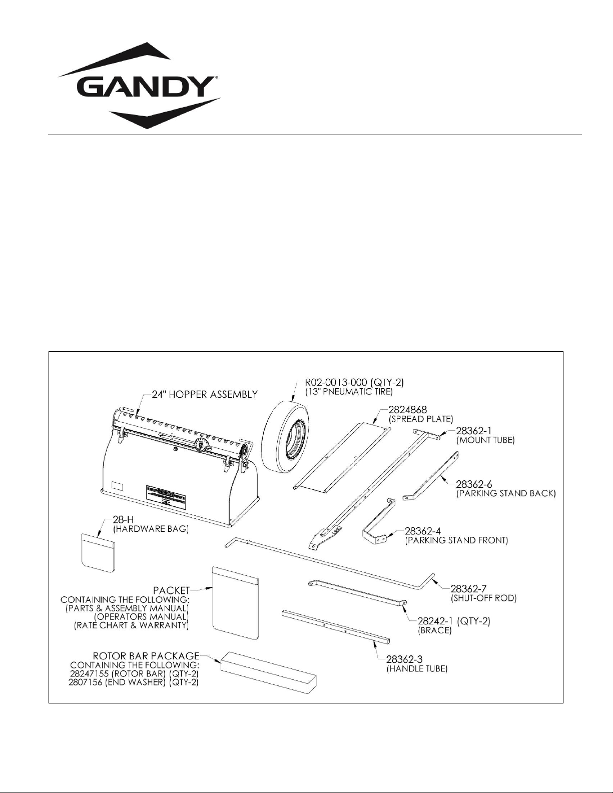
(All Hardware in Hardware Bag Unless Otherwise Specified)
Carton Containing the Following Parts:
Diagram #1
2824-B
Page 2 of 19
Rotor Bar Package (for 24” Spreader) Contents:
Diagram #2
2824-RP
Hardware Bag 28-H Contents:
Diagram #3
28-H
Note:
Part numbers C21-0177-020 (Qty-2) is not used in this spreader package.
Page 3 of 19
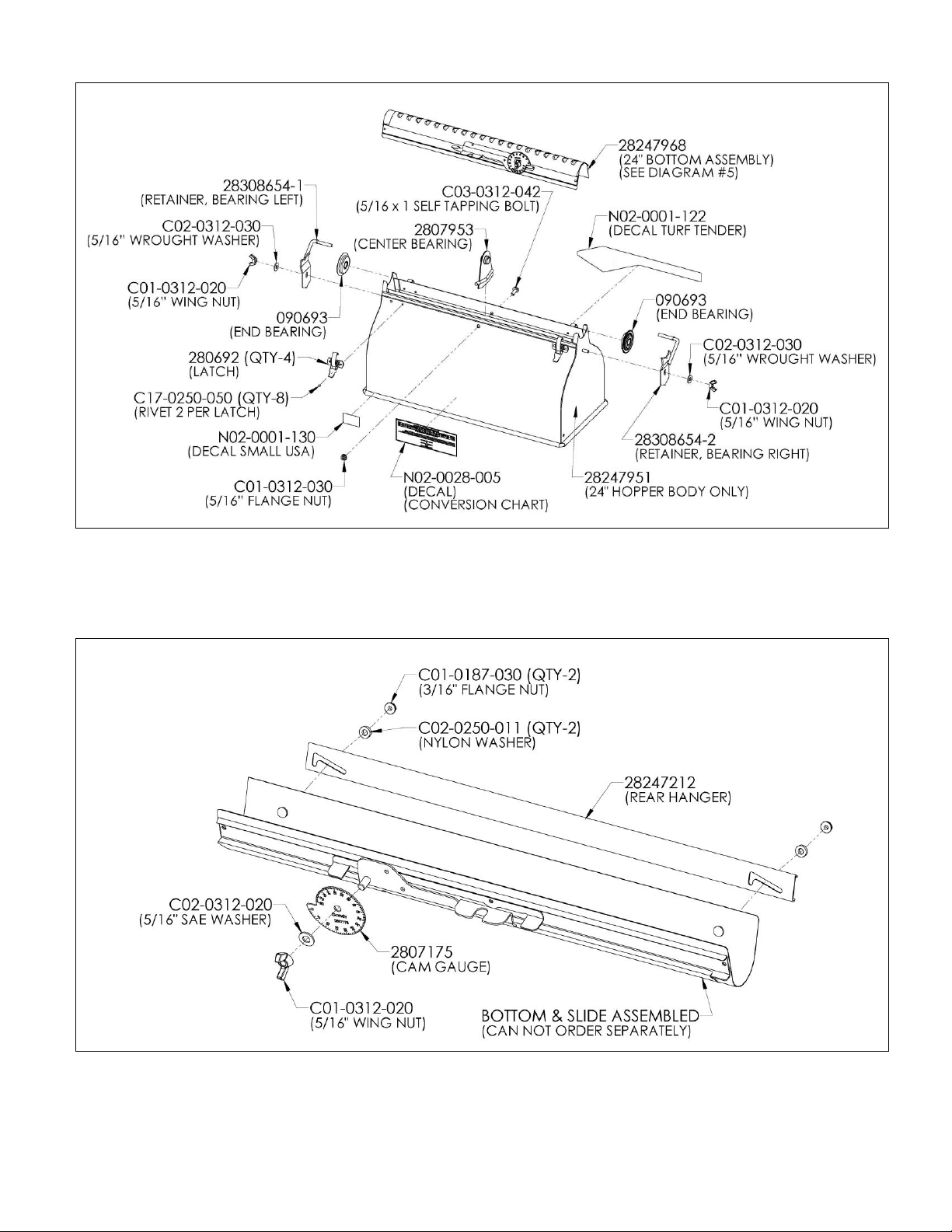
24” Hopper Assembly Schematic
Diagram #4
2824-A1
Bottom Assembly (28247968) Breakdown:
These parts are part of the Bottom Assembly but can be ordered separately.
Diagram #5
28247968
Page 4 of 19
Assembly Instructions: (All Hardware & Small Parts in Hardware Bag Unless Otherwise Specified)
Please read and review all instructions before starting to assemble.
Minimum tools required.
Pliers, Two 7/16” Wrenches & One 1/2" Wrench
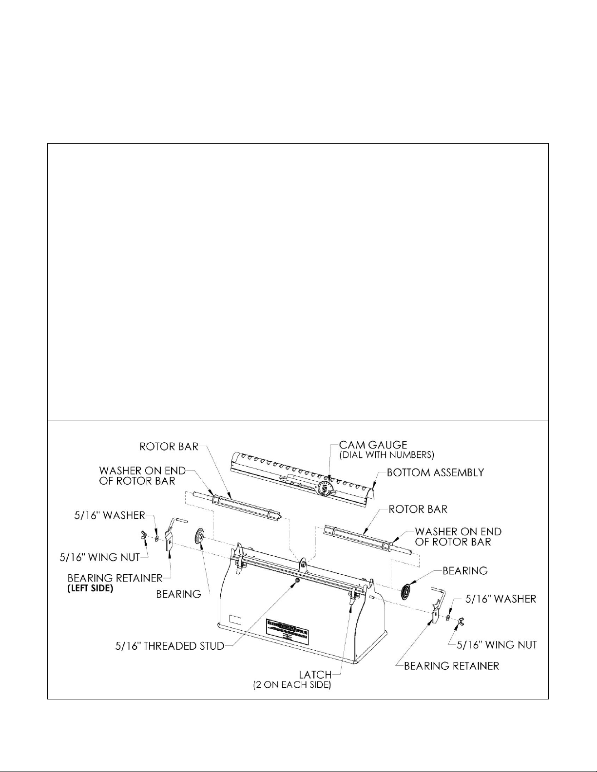
Step# 1 (Unpacking & Rotor Bar Assembly)
Remove contents from carton and check all parts against page #1 to confirm parts.
Un-wrap rotor bars, making sure one washer stays on each long end of rotor bar. (See Diagram #2 on page #2)
Carefully open the hardware bag and check all parts against page #2, Diagram #3 to confirm all parts.
1.
Note: Lay something down (piece of cardboard or blanket) to protect hopper from being scratched up.
Place hopper upside down with cam gauge facing you.
2.
Un-snap latches on hopper (two each side) and un-hook from bottom assembly.
3.
Remove bottom assembly from hopper by pulling straight up on it.
4.
Remove the 5/16”wing nut and washer from each bearing retainer and remove both bearing retainers.
Save the wing nuts & washer as they will be re-used latter.
5.
Remove both bearings from hopper. (Note: Bearing may fall out when removing bearing retainers.)
6.
Install rotor bars (short end of rotor bar) into center bearing.
7.
Slide bearing onto rotor bar (long end) up to hopper, making sure washer is still on rotor bar.
Repeat for other rotor bar. Make sure center bearing is standing straight up.
8.
Install bottom assembly back onto hopper. Cam gauge will be on same side as the 5/16”threaded stud.
9.
Make sure bearings are pushed into hopper, re-snap all four latches to hold bottom in place.
10.
Re-install left side bearing re-using the 5/16”washer and wing nut to hold bearing retainer in place.
When installing make sure the rod on the bearing retainer is on the opposite side of the cam gauge.
Other bearing retainer will be re-installed in the next step.
Diagram #6
2824-A1
Page 5 of 19
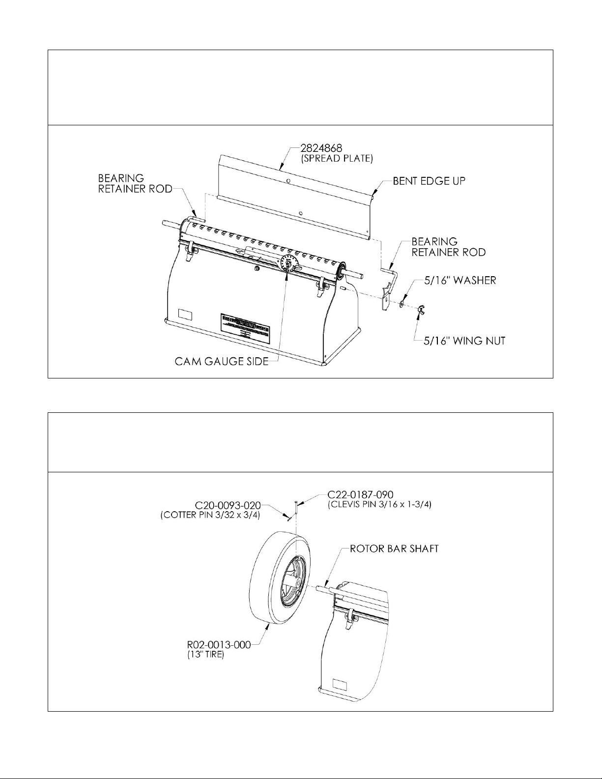
Step# 2 (Spread Plate Assembly)
1.
Locate Spread Plate (2824868).
2.
Slide rolled edge (side without bend) of spread plate onto bearing retainer rod as shown in Diagram #7.
3.
Re-install the last bearing retainer to hopper and spread plate re-using the 5/16”washer and wing nut.
3.
Adjust bearing retainers so spread plate can pivot freely. Tighten booth 5/16”wing nuts securely.
Diagram #7
2824-A1
Step# 3 (Tire Assembly)
Install tire (R02-0013-000) to rotor bar shaft end using the 3/16 x 1-3/4 clevis pin (C22-0187-090) and
3/32 x 3/4 cotter pin (C20-0093-020). Pin tire to the hole in the rotor bar that is closest to hopper.
Repeat for other tire.
Diagram #8
2836-A1
Page 6 of 19
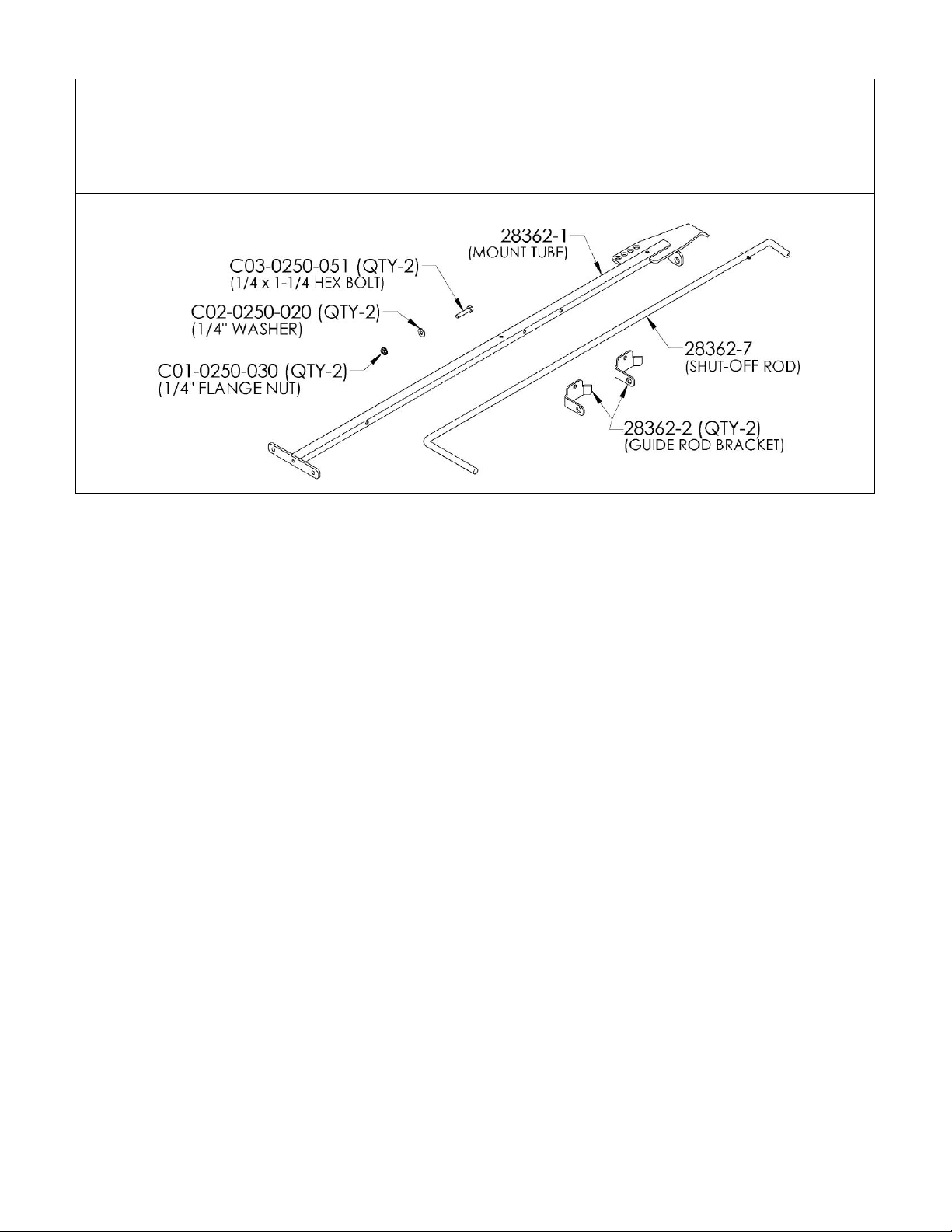
Step# 4 (Locate the Following Parts & Hardware)
Parts:
Mount Tube (28362-1)
Shut-Off Rod (28362-7)
Guide Rod Bracket (28362-2) (Qty-2)
Hardware:
1/4 x 1-1/4 Hex Bolts (C03-0250-051) (Qty-2)
1/4” Washers (C02-0250-020) (Qty-2)
1/4” Flange Nuts (C01-0250-030) (Qty-2)
Diagram #9
2836-A3
Page 7 of 19
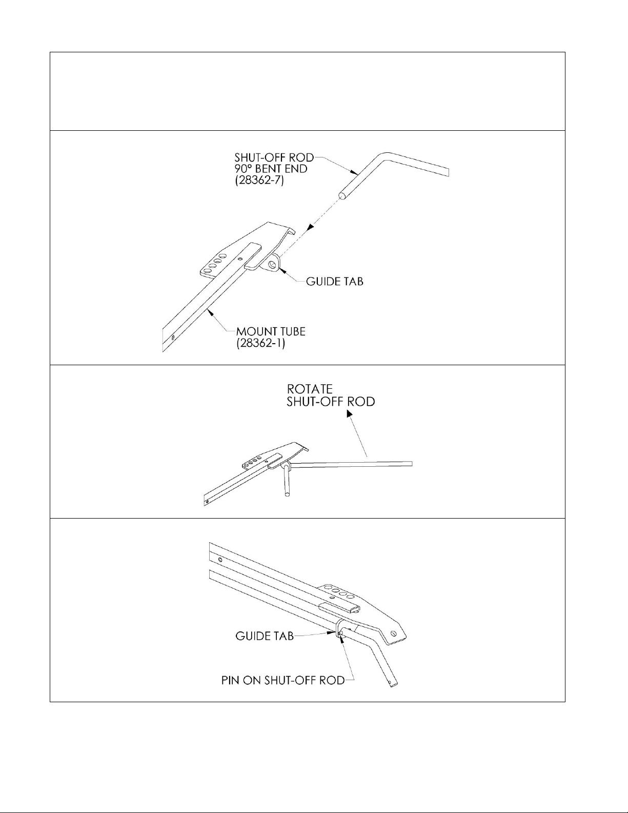
Step# 5 (Mount Tube & Shut-Off Lever Assembly)
1.
Insert the 90° bent end of shut-off rod (28362-7) through guide tab on mount tube (28362-1) as shown
in Diagram #10.
2.
When 90° bend on shut-off rod hits the guide tab rotate the shut-off rod (see diagram #11) and slide
shut-off rod until the spring pin touches the guide tab as shown in Diagram #12.
Diagram #10
2836-A2
Diagram #11
2836-A2-1
Diagram #12 (Installed View)
2836-A2-2
Page 8 of 19
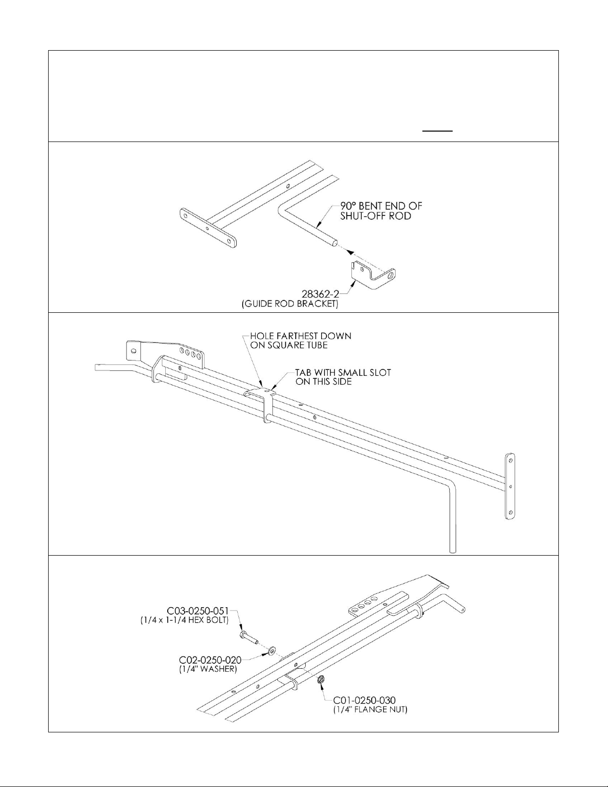
Step# 6 (First Guide Shut-Off Lever Assembly)
1.
Slide the first guide rod bracket (28362-2) over the 90° bent end of the shut-off rod and rotate around the
corner of the shut-off rod. Now slide guide all the way down the shut-off rod to the farthest hole down on
the square tube. When in place the tab with small slot will be on the opposite side of the square tube as
the shut-off rod as shown in Diagram #14.
2.
Fasten the guide in place as shown in diagram #15 using the listed hardware. Do not tighten bolt.
Diagram #13
Diagram #14
Diagram #15
2836-A12
Page 9 of 19
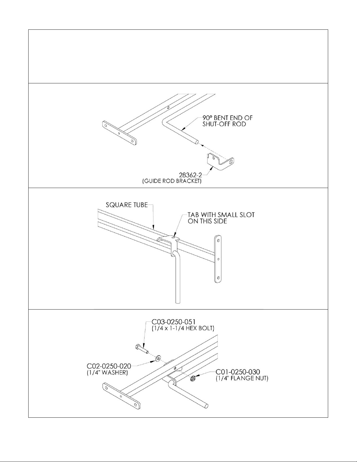
Step#7 (Second Guide Shut-Off Lever Assembly)
1.
Slide the second guide rod bracket (28362-2) over the 90° bent end of the shut-off rod and rotate around
the corner of the shut-off rod to the top hole on the square tube. When in place the tab with small slot will
be on the opposite side of the square tube as the shut-off rod as shown in Diagram #17.
2.
Fasten the guide in place as shown in diagram #16 using the listed hardware.
Tighten hardware from this step & last step securely.
Diagram #16
Diagram #17
Diagram #18
2836-A4
Page 10 of 19
Step# 8 (Mount Tube to Hopper Assembly)
1.
Note: Lay something down (piece of cardboard or blanket) to protect hopper from being scratched up.
Lay hopper on its side so the cam gauge is up & pivot the spread plate down out of the way as shown in
Diagram #19.
2.
Remove the 5/16”flange nut from the stud above and to the right of the cam gauge as shown
in Diagram #19.
3.
Attach the mount tube with shut-off rod in place to the 5/16” stud & re-use the 5/16”flange nut.
Make sure the end of the shut-off lever goes into the U-notch as shown in Diagram #20.
Do not tighten, leave nut loose.
Diagram #19
Diagram #20
2824-A2
Page 11 of 19
Step #9 (Left Brace to Mount Tube Assembly)
1.
Locate the TWO braces (28242-1), TWO 1/4 x 1/2 hex bolts (C03-0250-010), ONE 1/4 x 1-1/2 hex bolt (C03-
0250-061), THREE 1/4" flange nuts (C01-0250-030) and ONE 1/4" washer (C02-0250-020).
2.
Attach one end of the brace to the 1/4" hole in the left side of the hopper as shown in Diagram #21 using a
1/4 x 1/2 hex bolt and 1/4” flange nut as shown. Do not tighten bolt.
3.
Attach the other end of the brace to the 1/4” hole in the side of mount tube using a 1/4" washer, 1/4 x 1-
1/2 hex bolt and 1/4" flange nut. Do not tighten, leave loose.
Diagram #21
2824-A3
Page 12 of 19
Step #10 (Right Handle Brace Assembly)
1.
Attach the second brace (28242-1) to the 1/4” hole on the right side of the hopper using the 1/4 x 1/2 hex
bolt and 1/4" flange nut. Do not tighten bolt.
2.
Remove the 1/4" flange nut from the 1/4 x 1-1/2 bolt holding the left brace in place to the mount tube.
3.
Attach the other end of the brace to the 1/4 x 1-1/2 bolt and re-install the 1/4" flange nut.
4.
Next securely tighten the three 1/4" bolts holding the braces in place.
5.
Now securely tighten the 5/16”flange nut holding the mount tube to the hopper.
Diagram #22
2824-A3
Page 13 of 19
Step #11 (Parking Stand Assembly)
1.
Locate the following parts: front parking stand (28362-4), back parking stand (28362-6), TWO 1/4 x 5/8
carriage bolts (C04-0250-020) and TWO 1/4" flange nuts (C01-0250-030) as shown in Diagram #23.
2.
Fasten parking stands together using two carriage bolts and flange nuts as shown in Diagram #23.
Do not tighten, leave loose.
Diagram #23
2836-A7
Step #12 (Parking Stand to Mount Tube Assembly)
1.
Locate TWO 1/4 x 1-1/4 hex bolts (C03-0250-051), TWO 1/4" washers (C02-0250-020) and TWO 1/4" flange
nuts (C01-0250-030).
2.
Attach the long end of the parking stand to the top 1/4" hole in the mount tube using a 1/4 x 1-1/4 hex
bolt, 1/4" washer and 1/4" flange nut as shown in Diagram #24. Do not tighten.
3.
Attach the other end of the parking stand to the bottom 1/4" hole in the mount tube using the same
hardware as shown in Diagram #24. Do not tighten.
4.
Securely tighten the two carriage bolts from last step first and then then securely tighten the two bolts
from this step.
Diagram #24
2824-A4
Page 14 of 19
Step #13 (Sash Chain to Spread Plate Assembly)
1.
Locate Sash Chain (28368785-1) and the small hairpin cotter 1/8 x 1-15/16 (C21-0125-020).
2.
Insert sash chain into hole in spread plate as shown in Diagram #25.
3.
Connect the small hairpin cotter to the bottom most link on the sash chain.
4.
Pull sash chain up so the hairpin cotter contacts the spread plate.
Diagram #25
2836-A9
Step #14 (Connect Sash Chain to Handle)
Turn spreader upright so it sits up on its wheels and parking stand.
Pivot spread plate towards the hitch; then connect the S-Hook on the sash chain to the second hole up from the
hopper on the mount plate as shown in Diagram #26.
Diagram #26
2836-A9
Page 15 of 19
Step #15 (Handle Tube Assembly)
1.
Locate the following parts: Handle Tube (28362-3), TWO 1/4 x 1-1/4 hex bolts (C03-0250-051), TWO 1/4"
washers (C02-0250-020) and TWO 1/4” flange nuts (C01-0250-030).
2.
Attach the Handle Tube to the Mount Tube using the above listed hardware as shown in Diagram #27.
Tighten hardware securely.
Diagram #27
2836-A10
Step #16 (Grip Assembly)
Locate the two large grips and the small grip.
Push the small grip on the Shut-Off Rod as shown.
Push the large grip, one on each end of the Handle Tube as shown.
Diagram #28
2836-A11
Page 16 of 19
Step #17 (Lift Handle Assembly)
1.
Locate Lift Handle (2808886-9), TWO 1/4 x 1/2 hex bolts (C03-0250-010) and TWO 1/4" flange nuts (C01-
0250-030).
2.
Attach Lift Handle to the two 1/4" hole in the front of the hopper using the above listed hardware as
shown in Diagram #29. Tighten hardware securely.
Diagram #29
2824-A5
18. Spread Plate Adjustment:
As shown in Step #14 Diagram #26, connecting the spread plate chain to the second hole up from the hopper on
the mount tube plate is a good starting point for most material being applied to produce a “Sheet-Like” flow
coming off the spread plate.
Depending on your application rate and weight of the product being applied you may need to adjust the angle
up or down so the material flows freely off the spread plate.
If application without spread plate is desired, lift spreader up and swing spread plate to the lift handle side of
the spreader and hook the s-hook on the sash chain over the lip on the spreader.
See operator’s manual for more information.
19. Please read Operators Manual for overview of proper use, maintenance & cleaning of spreader.
Page 17 of 19
24” Spreader Parts Breakdown:
24H13-A1
Page 18 of 19
24” Push Handle Parts Breakdown:
24H13-A2
Page 19 of 19
13” Pneumatic Tire & Mount Hardware:
36H13-A3
Optional Equipment (NOT Part of Spreader Package)
Calibration Pan & Mounting Hardware: Package #28248584
Calibration pan hangs under the spreader to catch material to double check application rates.
28248584
Jiggler Package: Package #J24
Use Jigglers on bridging material.
When installed Jigglers contact the rotor bar and move up and down to help maintain an even material flow.
J24
24H13 (2019)
January 1, 2019
Printed in the USA

Other manuals for 24H13

1

Other Gandy Spreader manuals

Gandy 24H12 User manual

Gandy

Gandy 24H12 User manual

Gandy 36H12 User manual

Gandy

Gandy 36H12 User manual

Gandy 10T Series User manual

Gandy

Gandy 10T Series User manual

Gandy 36T13 User manual

Gandy

Gandy 36T13 User manual

Gandy 24H13 User manual

Gandy

Gandy 24H13 User manual

Gandy 10T Series User manual

Gandy

Gandy 10T Series User manual

Popular Spreader manuals by other brands

Ecolawn ECO250 Operator's manual

Ecolawn

Ecolawn ECO250 Operator's manual

Jonathan Green New American Lawn Standard Rotary Spreader instruction manual

Jonathan Green

Jonathan Green New American Lawn Standard Rotary Spreader instruction manual

dji T Series user manual

dji

dji T Series user manual

Agri-Fab 45-2142 owner's manual

Agri-Fab

Agri-Fab 45-2142 owner's manual

Modulift CMOD 34 User instructions

Modulift

Modulift CMOD 34 User instructions

U-Line H-2813 quick guide

U-Line

U-Line H-2813 quick guide

Boss Snowplow TGS 800 owner's manual

Boss Snowplow

Boss Snowplow TGS 800 owner's manual

SnowEx VX-4210 owner's manual

SnowEx

SnowEx VX-4210 owner's manual

BAUMAN 220 Operator's manual

BAUMAN

BAUMAN 220 Operator's manual

Meyer's 3465 INSTRUCTION AND PARTS BOOK

Meyer's

Meyer's 3465 INSTRUCTION AND PARTS BOOK

PRONAR T130 Operator's manual

PRONAR

PRONAR T130 Operator's manual

WilTec 50133 Operation manual

WilTec

WilTec 50133 Operation manual

Swisher 10272 instruction sheet

Swisher

Swisher 10272 instruction sheet

Bonjear BJ-S825 instruction manual

Bonjear

Bonjear BJ-S825 instruction manual

Land Pride PS25120 Operator's manual

Land Pride

Land Pride PS25120 Operator's manual

Meyer 7200 Operator and parts manual

Meyer

Meyer 7200 Operator and parts manual

Advantech VEGA-320 Startup manual

Advantech

Advantech VEGA-320 Startup manual

Western WB-160D Owner's manual and installation instructions

Western

Western WB-160D Owner's manual and installation instructions

manuals.online logo
manuals.online logoBrands
  • About & Mission
  • Contact us
  • Privacy Policy
  • Terms and Conditions

Copyright 2025 Manuals.Online. All Rights Reserved.