Table of contents 2/83
Table of contents
1 Introduction .............................................................................................................................. 4
1.1 About this document ........................................................................................................4
1.2 List of revisions ................................................................................................................4
1.3 Reference to hardware.....................................................................................................4
2 Descriptions ............................................................................................................................. 5
2.1 Key features .....................................................................................................................5
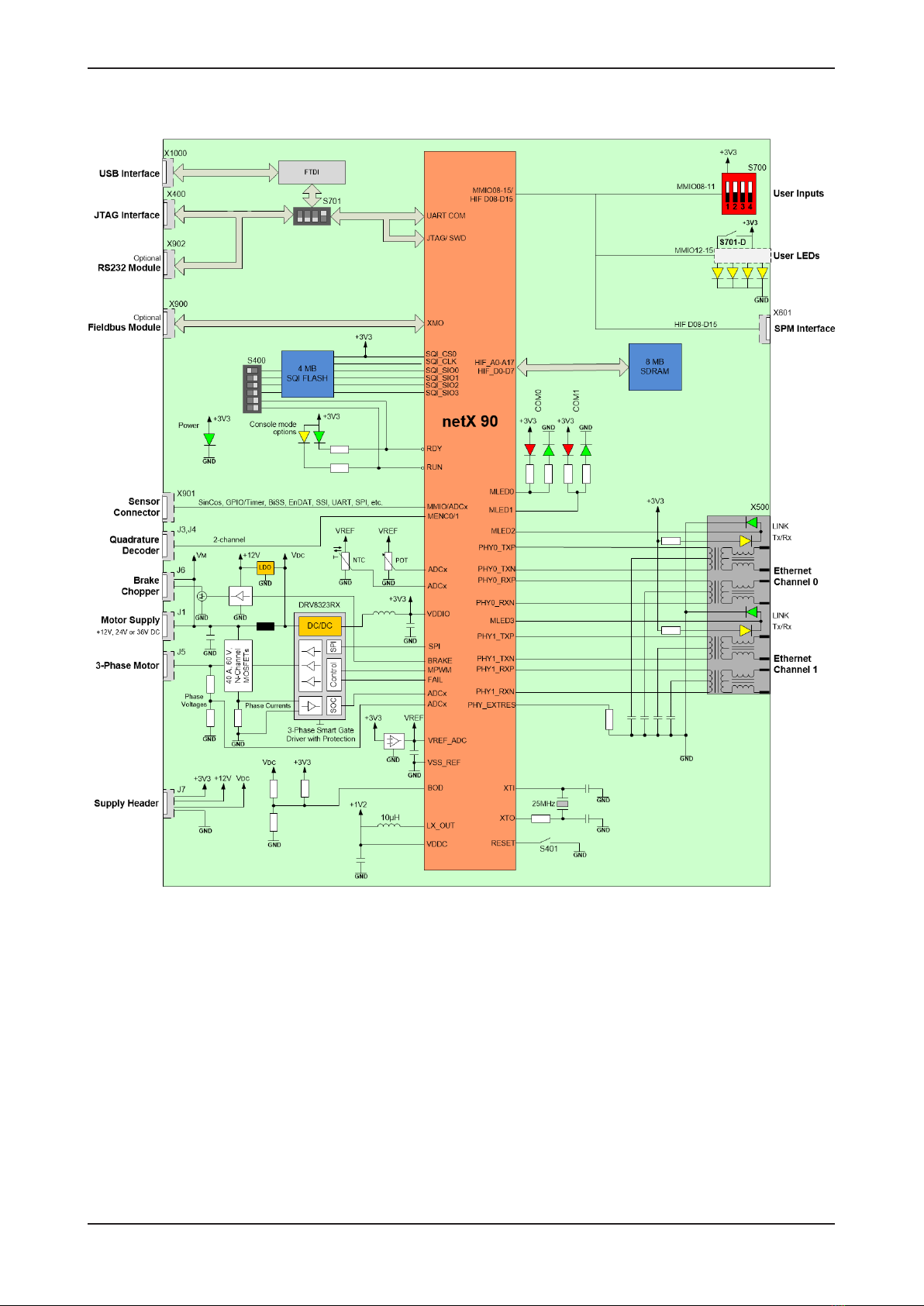
2.2 Block diagram ..................................................................................................................6
2.3 Board application .............................................................................................................7
2.4 Positions of interfaces and operating elements ...............................................................8
2.5 Operating elements........................................................................................................10
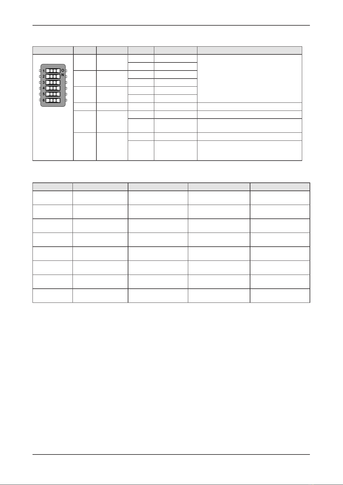
2.5.1 S400 – Slide switches for console mode and alternative boot mode.............. 10
2.5.2 S401 – Reset push button .............................................................................. 13
2.5.3 S700 – Slide switches for user-defined inputs ................................................ 13
2.5.4 S701 – Slide switches for selecting JTAG, UART, ADCs and user LEDs ...... 14
2.5.5 POT - Rotary potentiometer............................................................................ 14
2.6 Interfaces .......................................................................................................................15
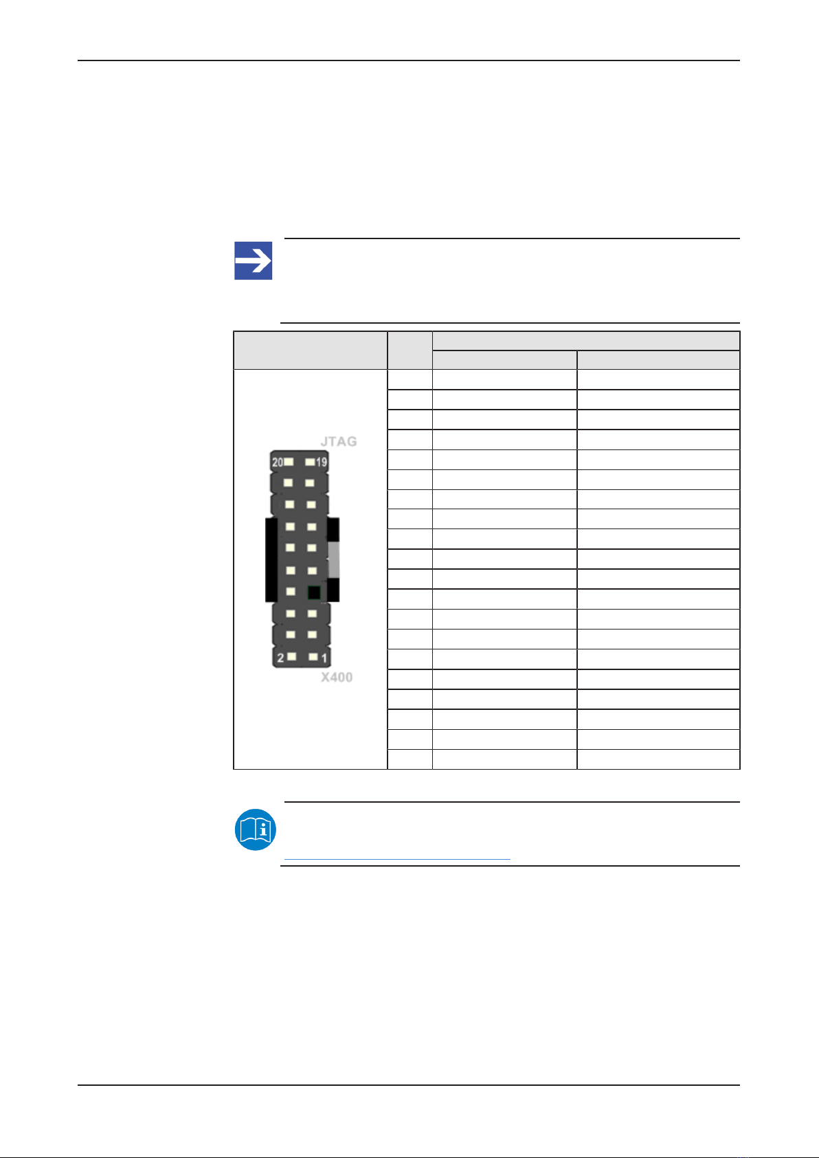
2.6.1 X400 – JTAG connector.................................................................................. 15
2.6.2 X500 – Ethernet connectors ........................................................................... 16
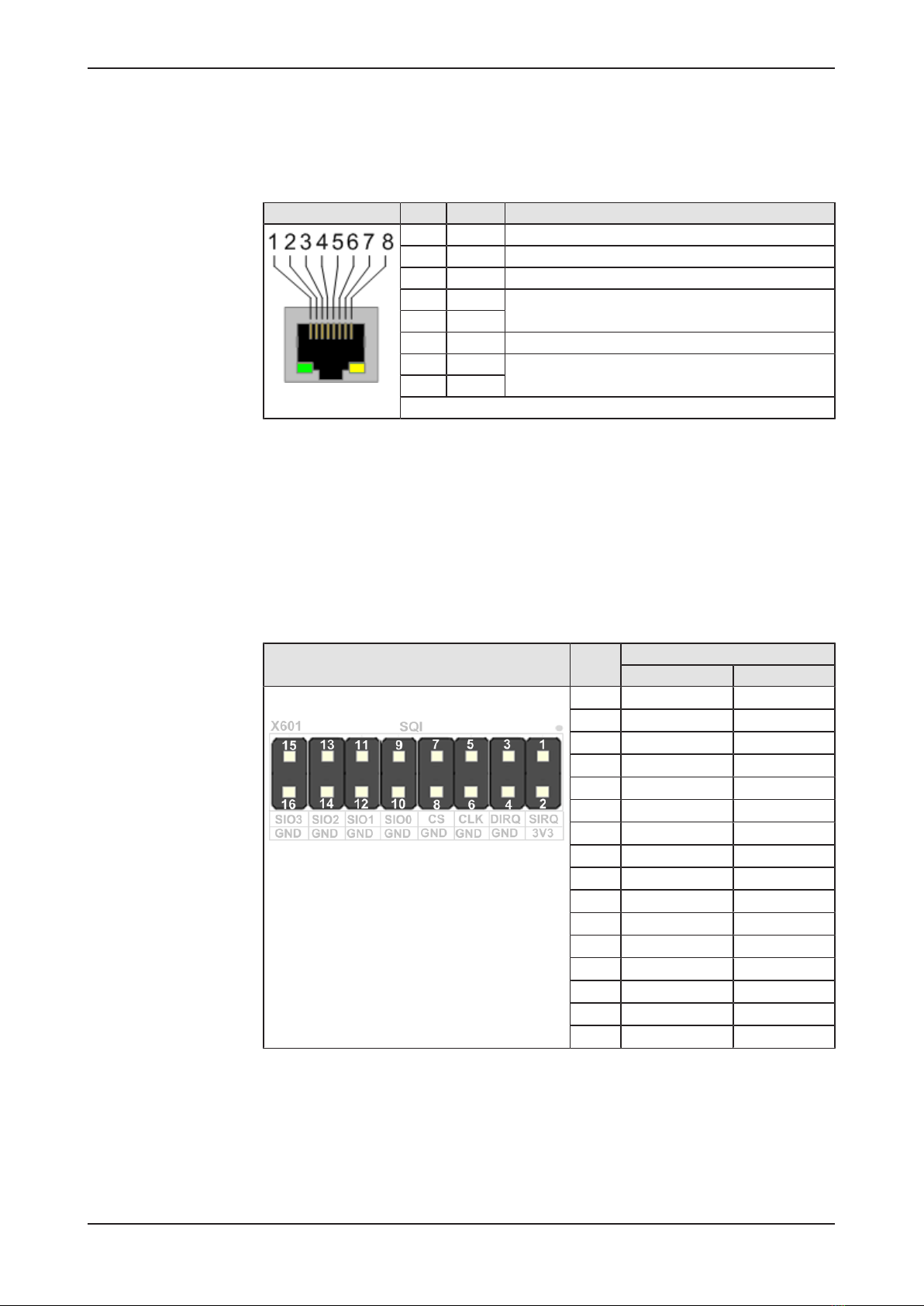
2.6.3 X601 – SPM host interface connector via SQI/SPI......................................... 16
2.6.4 X900 – Connector for NXHX fieldbus adapter modules.................................. 17
2.6.5 X901 – Sensor connector for NXHX-ENC and standard MMIOs.................... 18
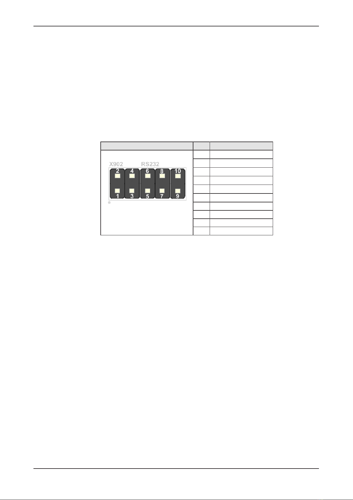
2.6.6 X902 – Connector for NXHX-RS232 adapter module (UART) ....................... 19
2.6.7 X1000 – Mini-B USB connector ...................................................................... 20
2.6.8 X1001 – Measuring points (vias) for UART via FTDI...................................... 20
2.6.9 J1 - Connector for power and motor supply.................................................... 21
2.6.10 J3, J4 - Quadrature Decoder Interface ........................................................... 22
2.6.11 J5 - 3-phase motor connector ......................................................................... 23
2.6.12 J6 - Brake chopper.......................................................................................... 23
2.6.13 J7 - Supply header.......................................................................................... 24
2.6.14 TP1 to TP44 – Test points .............................................................................. 25
2.7 LEDs ..............................................................................................................................26
3 Accessories............................................................................................................................ 28
3.1 Fieldbus interface adapter modules ...............................................................................28
3.1.1 Overview ......................................................................................................... 28
3.1.2 NXHX-DP........................................................................................................ 29
3.1.3 NXHX-CO ....................................................................................................... 29
3.1.4 NXHX-DN........................................................................................................ 30
3.1.5 NXHX-CC........................................................................................................ 30
3.2 NXHX-RS232 serial interface adapter ...........................................................................31
3.3 NXHX-ENC module........................................................................................................32
3.4 NXHX-DH adapter..........................................................................................................34
3.5 NXJTAG-USB ................................................................................................................35
4 Schematics ............................................................................................................................. 36
4.1 Schematics NXHX 90-MC..............................................................................................36
4.1.1 NXHX 90-JTAG / BOOSTXL-DRV8323RX..................................................... 37
4.1.2 NXHX 90-JTAG............................................................................................... 38
NXHX 90-MC | Device description
DOC200602HW01EN | Revision 1 | English | 2021-02 | Released | Public
© Hilscher 2021