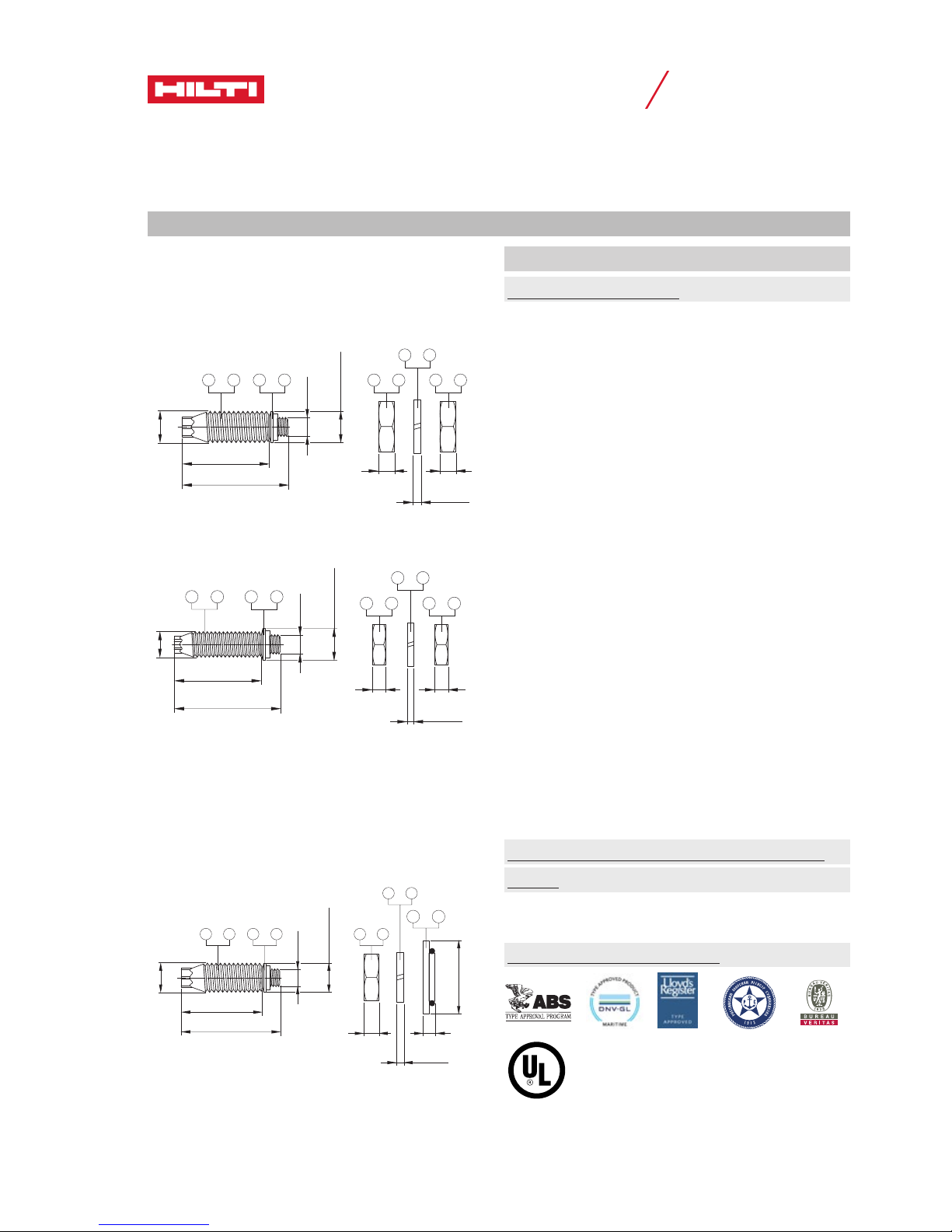
S-BT-ER and S-BT-EF screw-in stainless steel and carbon
steel threaded studs for electrical connections
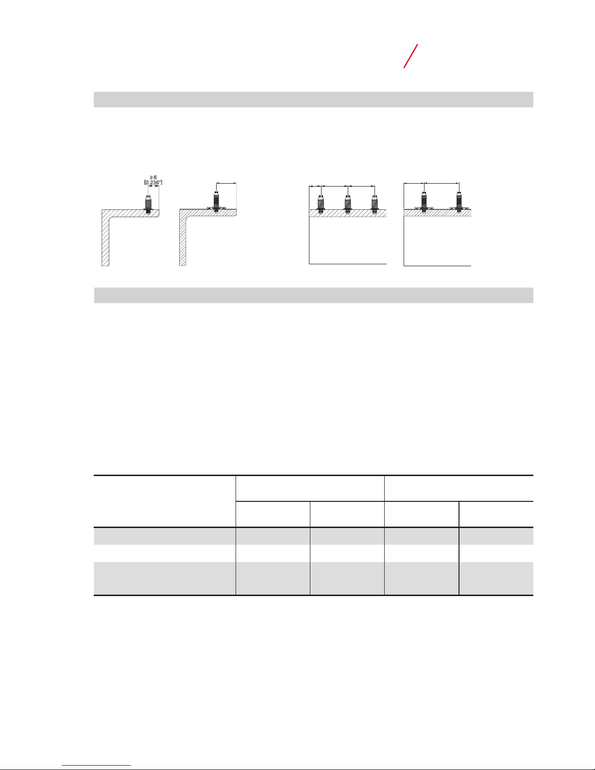
Dimensions
Product data
S-BT-ER M10/15 SN 6
S-BT-ER W10/15 SN 6
S-BT-EF M10/15 AN 6
S-BT-EF W10/15 AN 6
S-BT-ER M8/15 SN 6
S-BT-EF M8/15 AN 6
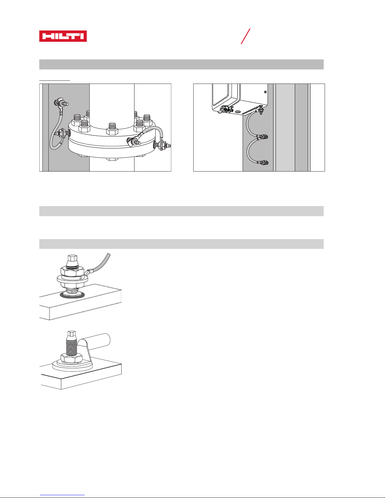
General information
Material specifications
ÀThreaded shank: Stainless steel (S-BT-ER)
“S 31803 (1.4462)”
zinc-coated
Á Threaded shank: Carbon steel (S-BT-EF)
“1038 / duplex-coated”
 SN12-R washers: Ø 12 mm [0.47”]
Stainless steel (S-BT-ER)
“S 31603 (1.4404)”
à AN10-F washers: Ø 10 mm [0.39”]
Aluminum (S-BT-EF)
ÄNut: Stainless steel (S-BT-ER)
grade A4 / AISI 316 material
Å Nut: Carbon steel (S-BT-EF)
HDG
Æ Lock washer: Stainless steel (S-BT-ER)
grade A4 / AISI 316 material
Ç Lock washer: Carbon steel (S-BT-EF)
HDG
È Conductivity disc: Ø 22 mm [0.866”]
(HC 35/AWG2)
Copper alloy CuSn8
(tin-coated) with sealing ring
É Conductivity disc: Ø 32 mm [1.260”]
(HC 120/AWG4/0)
Copper alloy CuSn8
(tin-coated) with sealing ring
Sealing ring of
sealing washers: Chloroprene rubber CR
3.1107, black, resistant to
UV, salt water, water, ozone,
oils etc.
Conductivity discs: Resistant to UV, salt water,
water, ozone, atmospheric
conditions etc.
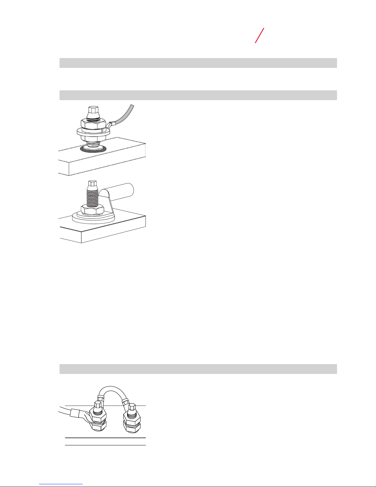
Drilling tool, setting tool, accessories and
inserts
Refer to section “Fastener selection and system
recommendation” for more details.
Reports and type approvals
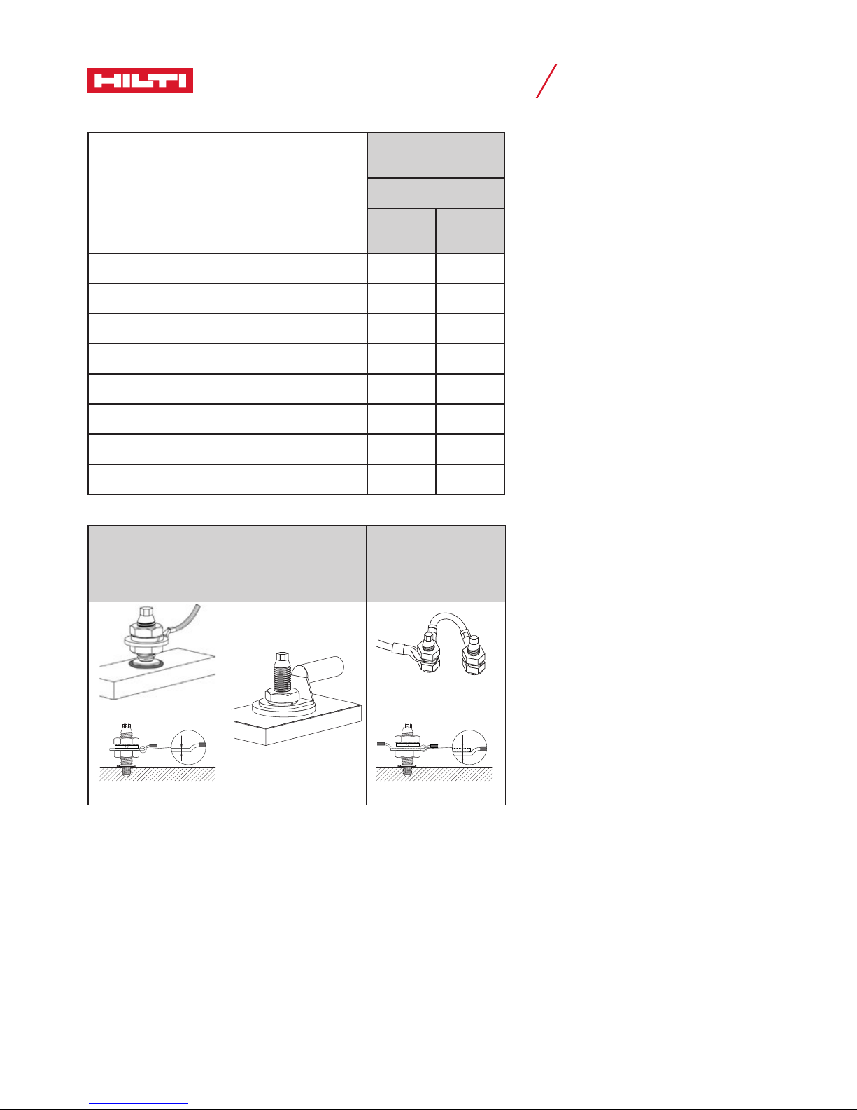
27.75 [1.1"]
33.9 [1.33"]
21or 43oror