Hilti UH 240-A User manual

UH 240-A
Operating instructions en
Mode d’emploi fr
Manual de instrucciones es
Printed: 07.07.2013 | Doc-Nr: PUB / 5071285 / 000 / 00

1
1
2
4 51
10
7
9
3 6
8
CSA certified according to US and Canadian safety standards
Homologué (conforme aux normes de sécurité américaines et canadiennes)
Producto homologado según normas de seguridad americanas y canadienses
Produto homologado de accordo com as normas de segurança americanas e canadianas
CUS
Printed: 07.07.2013 | Doc-Nr: PUB / 5071285 / 000 / 00

123
2
3
R
L
STOP
1-15
5791 15
4
5
Printed: 07.07.2013 | Doc-Nr: PUB / 5071285 / 000 / 00

6
7
1
Printed: 07.07.2013 | Doc-Nr: PUB / 5071285 / 000 / 00

1
en
It is essential that the operating instructions
are read before the tool is operated for the
first time.
Always keep these operating instructions
together with the tool.
Ensure that the operating instructions are with
the tool when it is given to other persons.
UH 240-A cordless hammer drill
1. General information
1.1 Signal words and their meaning
-CAUTION-
Used to draw attention to a potentially dangerous situa-
tion which could lead to minor personal injury or damage
to the equipment or other property.
-NOTE-
Used to draw attention to an instruction or other useful
information. Not used for dangerous situations or where
damage to the equipment or property could occur.
1.2 Pictograms
Contents Page
1. General information 1
2. General safety rules 2
3. Specific safety rules and symbols 3
4. Functional description 4
5. Technical data 5
6. Assembly 5
7. Operation 6
8. Care and maintenance 7
9. Tools and accessories 7
10. Troubleshooting 8
11. Manufacturer's warranty – tools 8
12. Disposal 9
Operating controls and parts
햲Quick release clutch
햳Side handle
햴Torque clutch setting ring
햵Forward / reverse switch
햶Control switch
(with electronic speed control)
햷3-speed gear selector switch
햸Motor brake
햹Rating plate
햺Battery release buttons (2)
햻Bit box
These numbers refer to the corresponding illustrations.
The illustrations can be found on the fold-out cover pages.
Keep these pages open while studying the operating
instructions.
In these operating instructions, the UH 240-A cordless
hammer drill with battery fitted is referred to as “the tool”.
Warning signs
General
warning
Warning:
electricity
Warning:
caustic
substances
Obligation signs
Wear
breathing
protection
Wear
ear
protection
Wear
protective
gloves
Wear
eye
protection
Warning:
hot surface
Symbols
Read the
operating
instructions
before use
Return waste material for
recycling
Do not dispose of
batteries with
general refuse
V = volts
–––
--- = direct current
no=noloadspeed
min–1 = revolutions per minute
j= hammer drilling
= rotation only
Printed: 07.07.2013 | Doc-Nr: PUB / 5071285 / 000 / 00

2
en
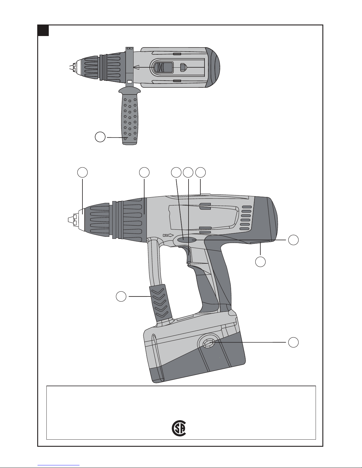
Location of identification data on the tool
The type designation, item number, year of manufacture
and technical status can be found on the rating plate on
the tool. The serial number is located on the left side of
the motor housing. Make a note of this data in your oper-
ating instructions and always refer to it when making an
enquiry to your Hilti representative or service depart-
ment.
Type:
Serial no.:
2. General safety rules
2.1 WARNING!
READ AND UNDERSTAND ALL INSTRUCTIONS
Failure to follow all instructions listed below, may result
in electric shock, fire and/or serious personal injury.
SAVE THESE INSTRUCTIONS.
2.2 Work Area
Keep your work area clean and well lit.
Cluttered benches and dark areas invite accidents.
Do not operate power tools in explosive atmospheres,
such as in the presence of flammable liquids, gases,
or dust.
Power tools create sparks which may ignite the dust or
fumes.
Keep bystanders, children, and visitors away while
operating a power tool.
Distractions can cause you to lose control.
2.3 Electrical safety
Do not abuse the cord. Never use the cord to carry the
tool. Keep cord away from heat, oil, sharp edges, or
moving parts. Replace damaged cords immediately.
Damaged cords may create a fire.
A battery operated tool with integral batteries or a se-
parate battery pack must be recharged only with the
specified charger for the battery.
A charger that may be suitable for one type of battery
may create a risk of fire when used with another battery.
Use battery operated tool only with specifically des-
ignated battery pack.
Use of any other batteries may create a risk of fire.
2.4 Personal safety
Stay alert, watch what you are doing, and use com-
mon sense when operating a power tool. Do not use
tool while tired or under the influence of drugs, alco-
hol, or medication.
A moment of inattention while operating power tools
may result in serious personal injury.
Dress properly. Do not wear loose clothing or jewel-
ry. Contain long hair. Keep your hair, clothing, and
gloves away from moving parts.
Loose clothes, jewelry, or long hair can be caught in
moving parts.
Avoid accidental starting. Be sure switch is in the
locked or off position before inserting battery pack.
Carrying tools with your finger on the switch or insert-
ing the battery pack into a tool with the switch on invites
accidents.
Remove adjusting keys or wrenches before turning
the tool on.
A wrench or a key that is left attached to a rotating part
of the tool may result in personal injury.
Do not overreach. Keep proper footing and balance at
all times.
Proper footing and balance enable better control of the
tool in unexpected situations.
Use safety equipment. Always wear eye protection.
Dust mask, non-skid safety shoes or hearing protection
must be used for appropriate conditions.
2.5 Tool Use and Care
Use clamps or other practical way to secure and sup-
port the workpiece to a stable platform.
Holding the work by hand or against your body is unsta-
ble and may lead to loss of control.
Do not force tool. Use the correct tool for your appli-
cation.
The correct tool will do the job better and safer at the
rate for which it is designed.
Do not use tool if switch does not turn it on or off.
A tool that cannot be controlled with the switch is dan-
gerous and must be repaired.
Disconnect battery pack from tool or place the switch
in the locked or off position before making any adjust-
ments, changing accessories, or storing the tool.
Such preventive safety measures reduce the risk of start-
ing the tool accidentally.
Printed: 07.07.2013 | Doc-Nr: PUB / 5071285 / 000 / 00

3
en
Store idle tools out of reach of children and other
untrained persons.
Tools are dangerous in the hands of untrained users.
When battery pack is not in use, keep it away from
other metal objects like: paper clips, coins, keys, nails,
screws, or other small metal objects that can make a
connection from one terminal to another.
Shorting the battery terminals together may cause sparks,
burns, or a fire.
Maintain tools with care. Keep cutting tools sharp and
clean.
Properly maintained insert tools with sharp cutting edge
are less likely to bind and are easier to control.
Check for misalignment or binding of moving parts,
breakage of parts, and any other condition that may
affect the tool’s operation. If damaged, have the tool
serviced before using.
Many accidents are caused by poorly maintained tools.
Use only accessories that are recommended by the
manufacturer for your model.
Accessories that may be suitable for one tool may cre-
ate a risk of injury when used on another tool.
2.6 Service
Tool service must be performed only by qualified repair
personnel.
Service or maintenance performed by unqualified per-
sonnel may result in a risk of injury.
When servicing a tool, use only identical replacement
parts. Follow instructions in the Maintenance section
of this manual.
Use of unauthorized parts or failure to follow Mainte-
nance Instructions may create a risk of shock or injury.
3. Specific safety rules and symbols
Hold tool by insulating gripping surfaces when per-
forming an operation where the cutting tool may con-
tact hidden wiring.
Contact with a „live“ wire will make exposed metal parts
of the tool „live“ and shock the operator.
Wear ear protectors when using the tool for extended
periods.
Prolonged exposure to high intensity noise can cause
hearing loss.
3.1 Take the necessary precautions to make the
workplace safe
GConcealed electric cables or gas and water pipes pre-
sent a serious hazard if damaged while you are working.
Accordingly, check the area in which you are working
beforehand (e.g. using a metal detector). Avoid con-
tact between your body and earthed / grounded objects,
such as pipes or radiators. External metal parts of the
tool may become live, for example, when an electric
cable is drilled into inadvertently.
GDo not expose the tool to rain or snow.
GUse the dust shield (accessory) to protect the chuck
when drilling overhead.
3.2 Additional general safety precautions
GKeep the grips dry, clean and free from oil and grease.
GDo not touch the chuck while it is rotating.
GNever leave the tool unsupervised.
GSwitch the tool on only after bringing it into position
at the workpiece.
GDo not insert wires or other similar objects into the
ventilation slots.
GThe tool may be operated only when the bit box is
closed.
3.2.1 Mechanical hazards
GCheck that the insert tools used are compatible with
the chuck system and that they are secured in the chuck
or gear housing correctly.
GUse only original Hilti insert tools.
3.2.2 Electrical hazards
GEnsure that the outer surfaces of the battery are clean
and dry before inserting it in the corresponding charger.
GUse only the batteries listed in these operating instruc-
tions (see section 5).
GCheck that the battery is securely attached to the tool.
A falling battery could injure you or other persons.
GBatteries that have reached the end of their life must
be disposed of safely (see section 12).
GEnsure that batteries are charged using the correct
charger recommended by the manufacturer. Incorrect
Printed: 07.07.2013 | Doc-Nr: PUB / 5071285 / 000 / 00

4
en
use may result in a risk of electric shock, overheating
or leaking of corrosive liquid from the battery.
3.2.3 Thermal hazards
GThe insert tool may become hot during use. You should
therefore wear protective gloves when changing insert
tools.
3.2.4 Liquids
GA caustic liquid may leak from defective batteries. Avoid
contact with this liquid. In the event of contact with the
skin, wash the area affected with soap and plenty of
water. Should the liquid come into contact with the
eyes, flush the eyes with water immediately and sub-
sequently consult a doctor.
3.3 Requirements to be met by users
GThe tool is intended for professional use.
GThe tool may be operated, serviced and repaired only
by authorized, trained personnel. This personnel must
be informed of any special hazards that may be encoun-
tered.
3.4 Personal protective equipment
GThe operator and other persons in the immediate vicin-
ity must always wear eye protection, ear protection
and breathing protection while the tool is in use.
3.5 Symbols used on the tool
V = volts
–––
--- = direct current
no=noloadspeed
min–1 = revolutions per minute
j= hammer drilling
= rotation only
∅= diameter
Wear
breathing
protection
Wear
ear
protection
Wear
protective
gloves
Wear
eye
protection
4. Functional description
The UH 240-A is a cordless hammer drill for professional
use.
The tool is suitable for use by right or left-handed
persons. The ergonomically designed rubber-padded
grip reduces fatigue and is designed to provide a secure
hold.
The items supplied include: Electric tool with side handle,
3 bits and magnetic bit holder, two B24/2.0 NiCd, B24/2.4
NiCd or B24/3.0 NiMH batteries, C 7/24, C 7/36-ACS
charger in toolbox or cardboard box.
4.1 Correct use
The UH 240-A is a hand-held cordless hammer drill for
driving and removing screws, drilling in steel, wood and
masonry and hammer drilling in masonry only.
It is intended for use on construction sites of all kinds
for general construction, interior finishing, conversion
and renovation work.
GThe tool may be used only in a dry environment.
GDo not use the tool where there is a risk of fire or explo-
sion.
GUse only the insert tools and accessories intended for
use with this tool.
GThe tool may be powered only by the batteries approved
for use with this tool.
GDo not use the batteries as a power source for other
equipment.
GUse only the recommended battery charger.
GModification or manipulation of the tool other than
described in these operating instructions is not per-
missible.
GTo avoid the risk of injury, use only original Hilti acces-
sories and additional equipment.
GObserve the information printed in the operating instruc-
tions concerning operation, care and maintenance.
GThe tool and its ancillary equipment may present haz-
ards when used incorrectly by untrained personnel or
when used not as directed.
4.2 Important features of the tool
– Vibration-absorbing grip (rubber-padded)
– Smooth speed control
– Gearing and clutch with permanent lubrication
(grease)
– Automatic cut-out carbon brushes
– Forward / reverse rotation
Printed: 07.07.2013 | Doc-Nr: PUB / 5071285 / 000 / 00

5
en
6. Assembly
1. It is essential that the safety precautions printed in
these operating instructions are read and observed.
2. It is essential that a new battery is charged correctly
before initial use so that the battery cells can form
correctly. Incorrect initial charging can lead to a per-
manent reduction of battery capacity.
– With the C 7/24 charger: Charge for 24 hours in nor-
mal charging mode or for 12 hours in conditioning
mode.
– With the C 7/36-ACS charger: The charger detects
automatically whether initial charging or normal
charging is necessary.
-NOTE-
GThe tool may be used only with B24/2.0 NiCd, B24/2.4
NiCd or B24/3.0 NiMH batteries.
GBattery performance drops at low temperatures.
GBatteries should be stored at room temperature.
GNever store batteries where they are exposed to the
heat of the sun, on a radiator, behind a motor vehicle
windscreen or at a window.
GNever use the battery until the cells become fully dis-
charged. Change to the second battery as soon as a
drop in performance is noticed and recharge the bat-
tery immediately so that it is ready for re-use.
GUse bits with a standard 1/4″hex. shank.
6.1 Fitting the side handle
1. Open the side handle clamping band by turning the
handle.
2. Slide the side handle clamping band over the chuck
and onto the tool.
3. Pivot the side handle into the desired position.
4. Secure the side handle by turning the handle.
5. Technical data
Tool
Rated voltage 24 V –––
---
Weight of tool including battery and chuck 3.8 kg (8.3 lb)
Dimensions (L×H×W) 320x286x92 mm (12.6x11.2x3.6 in)
Speed 1st gear: 0– 350 r.p.m.
2nd gear:0– 1300 r.p.m.
3rd gear: 0– 1950 r.p.m.
Chuck / clamping dia. range (quick-release chuck) 1.5–13 mm (0.06–0.5 in)
Torque Max. 45 Nm (at drilling setting)
Torque adjustment 5–17 Nm (in 15 increments)
Speed control Electronic control switch
Forward / reverse Electrical switch with interlock to prevent activation
when running
Spindle lock When control switch is in the “off” position
Motor brake By way of the control switch
Gearing section sealed to prevent entry of dust and with permanent lubrication (maintenance-free)
Battery B24/2.0 NiCd B24/2.4 NiCd B24/3.0 NiMH
Rated voltage 24 V –––
--- 24 V –––
--- 24 V –––
---
Battery capacity 24 V ×2.0 Ah 24 V ×2.4 Ah 24 V ×3.0 Ah
=48Wh =58Wh =72Wh
Weight 1.38 kg (3.0 lb) 1.38 kg (3.0 lb) 1.45 kg (3.2 lb)
Temperature monitoring yes yes yes
Type of cell Nickel-cadmium Nickel-cadmium Nickel-metal hydride
SUBCtype SUBCtype SUBCtype
No. of cells 20 20 20
Right of technical changes reserved!
Printed: 07.07.2013 | Doc-Nr: PUB / 5071285 / 000 / 00

6
en
7. Operation
-CAUTION-
GThe screwdriving procedure may
cause the material to splinter.
GSplintering material may cause injury
to the body, respiratory passages and
the eyes.
GWear eye and breathing protection.
-CAUTION-
GNoise is emitted by the tool and the
screwdriving or drilling procedure.
GExcessive noise may damage the
hearing.
GWear ear protection.
7.1 Setting forwards or reverse rotation
The direction of rotation can be selected by operating the
forward / reverse push switch 햵. An interlock prevents
operation of the switch while the motor is running. When
in the middle position, the on / off switch is locked.
– Forwards rotation: Push the forward / reverse switch
to the right (as seen from the direction in which the
tool is used).
– Reverse rotation: Push the forward / reverse switch
to the left (as seen from the direction in which the tool
is used).
7.2 Setting the speed (3-speed gear selector switch)
-CAUTION-
Operate the gear selector switch only when rotation has
stopped.
1. Set the switch to position 1 for a speed range of 0–
350 r.p.m., position 2 for a speed range of 0–1300
r.p.m. or position 3 for a speed range of 0–1950 r.p.m.
7.3 Screwdriving
1. Set the desired direction of rotation by way of the for-
ward / reverse switch.
7.3.1 Torque setting
1. Set the torque by turning the torque clutch setting
ring to the desired torque setting(1–15).
7.4 Hammer drilling
1. Turn the torque clutch setting ring to the hammer
drilling symbol.
-CAUTION-
Take care to avoid pinching the fingers between the chuck
and setting ring.
7.5 Drilling
1. Turn the torque clutch setting ring to the drilling symbol.
-CAUTION-
A high torque is experienced if the insert tool sticks while
drilling with large-diameter drill bits and hole saws.
Accordingly, use the side handle and hold the tool with
both hands (one hand on the grip and one hand on the
side handle).
7.6 Switching on and off
Should a sticking drill bit cause the motor to stall for
longer than 2–3 seconds, the tool must be switched off
in order to avoid damage to it.
1. Use the forward / reverse switch to select the direc-
tion of rotation.
2. The speed of the tool can be controlled smoothly
between zero and maximum by pressing the on / off
switch slowly.
7.7 Removing the battery (2-finger operation)
1. Press in both release buttons.
2. Pull the battery downwards out of the tool.
7.8 Fitting the battery
Use only Hilti B24/2.0 NiCd, B24/2.4 NiCd or B24/3.0
NiMH batteries.
1. Push the battery into the tool from below until it is
heard to engage.
7.9 Charging the battery
The battery cannot be charged through the belt adap-
tor.
Use only the Hilti C 7/24, C 7/36-ACS chargers.
Incorrect use may lead to electric shocks, overheating
of the battery or leakage of a caustic liquid from the bat-
tery.
Read the operating instructions for the charger before
beginning charging.
7.10 Changing the insert tool
-CAUTION-
GThe insert tool may become hot during
use.
GThere is a risk of burning the hands.
GWear protective gloves when chan-
ging insert tools.
Printed: 07.07.2013 | Doc-Nr: PUB / 5071285 / 000 / 00

7
en
8. Care and maintenance
8.1 Care of insert tools
Remove any dirt adhering to the surface of the insert
tools and protect them from corrosion by rubbing them
with an oily cloth from time to time.
8.2 Care of the tool
Before cleaning, remove the battery from the tool in order
to prevent inadvertent starting.
The outer casing of the tool is manufactured from impact-
resistant plastic. The grip comprises a synthetic rubber
section.
The ventilation slots must be unobstructed and kept clean
at all times. Use a dry brush to clean the ventilation slots
carefully. Do not permit foreign objects to enter the inte-
rior of the tool. Use a slightly damp cloth to clean the out-
side of the tool at regular intervals. Do not use a spray,
steam-cleaning system or running water for cleaning.
This may negatively affect the electrical safety of the tool.
Always keep the grip sections of the tool free from oil
and grease. Do not use cleaning agents or polishes, etc.
containing silicone.
8.3 Maintenance
Check all external parts of the tool for damage at regular
intervals and check that all controls operate faultlessly.
Do not operate the tool when parts are damaged or when
the controls do not operate faultlessly. If necessary, have
the tool repaired at a Hilti service center.
Electrical parts of the tool may be repaired only by trained
electrical specialists.
8.4 Care of the battery
Keep the electrical contacts free from dust, oil and grease.
If necessary, use a clean cloth to clean the contact sur-
faces.
Do not continue to operate the tool until the battery is
completely discharged as this may damage the battery
cells. Recharge the battery as soon as a drop in perfor-
manceisnoticed.
At monthly intervals or, at the latest, when battery capa-
city drops significantly, the battery should be conditioned
as follows:
– With the C 7/24 charger: Charge for 24 hours in nor-
mal charging mode or for 12 hours in conditioning
mode.
– With the C 7/36-ACS charger: The charger detects
automatically whether initial charging or normal char-
ging is necessary.
If, after conditioning, battery capacity is still unsatisfac-
tory, we recommend returning the battery to Hilti for diag-
nosis.
8.5 Checking the tool after care and maintenance
After carrying out care and maintenance work on the tool,
check that all protective and safety devices are fitted and
that they function faultlessly.
9. Accessories
Magnetic bit holder S-BH 50M
Bits EU USA
Pozidrive S-B PZD 3T 2 Phillips S-B PH 3×2″
Torx S-B TX 30T 1 Phillips S-B PH SQ2
Torx S-BTX40
Charger C 7/24
Charger C 7/36-ACS
Battery B24/2.0 NiCd, B24/2.4 NiCd or B24/3.0 NiMH
Toolbox / cardboard box
Belt adaptor BAP 24
Dust shield
Printed: 07.07.2013 | Doc-Nr: PUB / 5071285 / 000 / 00

8
en
11. Manufacturer's warranty – tools
Hilti warrants that the tool supplied is free of defects
in material and workmanship. This warranty is valid so
long as the tool is operated and handled correctly,
cleaned and serviced properly and in accordance with
the Hilti Operating Instructions, and the technical sys-
tem is maintained. This means that only original Hilti
consumables, components and spare parts may be
used in the tool.
This warranty provides the free-of-charge repair or
replacement of defective parts only over the entire lifes-
pan of the tool. Parts requiring repair or replacement
as a result of normal wear and tear are not covered by
this warranty.
Additional claims are excluded, unless stringent
national rules prohibit such exclusion. In particular,
Hilti is not obligated for direct, indirect, incidental
or consequential damages, losses or expenses in
connection with, or by reason of, the use of, or inabil-
ity to use the tool for any purpose. Implied warranties
of merchantability or fitness for a particular purpose
are specifically excluded.
For repair or replacement, send tool or related parts
immediately upon discovery of the defect to the address
of the local Hilti marketing organization provided.
This constitutes Hilti's entire obligation with regard to
warranty and supersedes all prior or contemporane-
ous comments and oral or written agreements con-
cerning warranties.
Fault Possible cause Remedy
Tool doesn‘t run Battery is discharged or not correctly Refit the battery. It must be heard to engage
fitted with an audible “click”. Charge the battery if
necessary.
Electrical fault Remove the battery and contact your
nearest Hilti service center.
Tool runs too fast / too Adjust the 3-speed gear selector Set the 3-speed gear selector switch to the
slow switch. desired position.
No hammer action Tool set to the wrong mode Set the tool to hammer drilling mode.
Clutch releases while drilling Tool set to screwdriving mode Set the tool to drilling mode.
On / off switch cannot be Forward / reverse switch is set to Move the forward / reverse switch to the
pressed middle position left/right.
Speed suddenly drops The battery is almost exhausted. Stop working with the exhausted battery
and charge it fully.
Battery becomes dis- Battery condition is not optimal. Charge the battery using conditioning mode
charged faster than usual (see battery charger operating instructions).
Battery does not engage Dirt on battery locking mechanism Clean battery locking mechanism and refit
with an audible “click” the battery. Contact your nearest Hilti ser-
vice center if the problem persists.
Tool or battery overheats Electrical fault. Switch off the tool immediately. Remove
the battery and contact your nearest Hilti
service center.
Overload due to exceeding Select the right tool for the application.
application limit
Drill bit or screwdriving bit Chuck not tightened correctly Tighten the chuck securely by applying
slips in the chuck reasonable force.
10. Troubleshooting
Printed: 07.07.2013 | Doc-Nr: PUB / 5071285 / 000 / 00

9
en
12. Disposal
Most of the materials from which Hilti power tools are manufactured can be recycled. The materials must be cor-
rectly separated before they can be recycled. In many countries, Hilti has already made arrangements for taking
back your old electric tools for recycling. Please ask your Hilti customer service department or Hilti sales repre-
sentative for further information. Should you wish to return the electric tool yourself to a disposal facility for recy-
cling, proceed as follows: Dismantle the tool as far as possible without the need for special tools. Use absorbent
paper to wipe greasy parts clean and collect any grease that runs out. This paper should also be disposed of cor-
rectly. On no account should grease be allowed to enter the waste water system or find its way into the ground.
Separate the individual parts as follows:
Part / assembly Main material Recycling
Toolbox Plastic Plastics recycling
Outer casing Plastic / synthetic rubber Plastics recycling
Electronic switch Various Electronics scrap
Motor Steel, copper Scrap metal
Gearing parts Steel Scrap metal
Battery Nickel-cadmium
Nickel-metal hydride **
Screws, small parts Steel Scrap metal
* Return waste material for recycling.
** Dispose of the battery in accordance with national regulations or return used
* ** batteries to Hilti for recycling.
Disposal
Batteries
The Hilti B24/2.0 NiCd and B24/2.4 NiCd battery has 20 nickel-cadmium cells.
The Hilti B24/3.0 NiMH battery has 20 nickel-metal hydrid cells.
Both you and Hilti bear the responsibility for recycling of the worn-out batteries in
keeping with environmental protection requirements.
Important: Do not throw worn-out batteries into household waste, a fire or water.
Dispose of the batteries in accordance with national regulations or return them to
Hilti.
Printed: 07.07.2013 | Doc-Nr: PUB / 5071285 / 000 / 00

Printed: 07.07.2013 | Doc-Nr: PUB / 5071285 / 000 / 00

11
fr
Avant de mettre l'appareil en marche, lire
impérativement son mode d'emploi et bien
respecter les consignes.
Le présent mode d'emploi doit toujours
accompagner l'appareil.
Ne pas prêter ou céder l'appareil à un autre
utilisateur sans lui fournir le mode d'emploi.
UH 240-A Perceuse à percussion sur accu
1. Consignes générales
1.1 Termes signalant un danger
-ATTENTION-
Pour attirer l'attention sur une situation pouvant pré-
senter des dangers susceptibles d'entraîner des bles-
sures corporelles légères ou des dégâts matériels.
-REMARQUE-
Pour des conseils d'utilisation et autres informations
utiles.
1.2 Pictogrammes
Sommaire Page
1. Consignes générales 11
2. Règles générales de sécurité 12
3. Règles de sécurité particulières et symboles 13
4. Description 14
5. Caractéristiques techniques 15
6. Mise en marche 15
7. Utilisation 16
8. Nettoyage et entretien 17
9. Outils et accessoires 17
10. Guide de dépannage 18
11. Garantie constructeur des appareils 18
12. Recyclage 19
Organes de commande et éléments de l'appareil
햲Mandrin à serrage rapide
햳Poignée latérale
햴Bague de réglage pour le couple de rotation
햵Inverseur du sens de rotation droite / gauche
햶Interrupteur de commande
(avec variateur de vitesse électronique)
햷Commutateur à 3 vitesses
햸Arrêt moteur
햹Plaque signalétique
햺Bouton de déverrouillage du bloc-accu
(2 éléments)
햻Boîtier à embouts
Les nombres renvoient aux illustrations se trouvant
sur les pages rabattables. Pour lire le mode d'emploi,
rabattre ces pages de manière à voir les illustrations.
Dans le texte du présent mode d'emploi, le terme "appa-
reil"désigne toujours la perceuse à percussion sur accu
UH 240-A avec un bloc-accu encliqueté.
Symboles d'avertissement
Avertisse-
ment danger
général
Avertissement
tension électrique
dangereuse
Avertissement
matières
corrosives
Symboles d'obligation
Porter un
masque respi-
ratoire léger
Porter un
casque anti-
bruit
Porter des
gants de
protection
Porter des
lunettes de
protection
Avertissement
surfaces
chaudes
Symboles
Lire le mode
d'emploi avant
toute utilisation
Recycler les déchets Les blocs-accus ne
doivent pas être
éliminés avec les
ordures ménagères
V=Volt
–––
--- = Courant continu
no= Vitesse nominale à vide
min–1 = Tours par minute
j= Perçage à percussion
= Perçage
Printed: 07.07.2013 | Doc-Nr: PUB / 5071285 / 000 / 00

12
fr
Emplacement des détails d'identification sur l'appareil
La désignation du modèle, le code d'article, l'année de
fabrication et l'état technique de votre appareil figurent
sur sa plaque signalétique. Son numéro de série figure
sur le côté gauche du carter-moteur. Inscrire ces ren-
seignements dans le mode d'emploi et toujours s'y réfé-
rer pour communiquer avec notre représentant ou agence
Hilti.
Type :
N° de série :
2. RÈGLES GÉNÉRALES DE SÉCURITÉ
2.1 AVERTISSEMENT!
Vous devez lire et comprendre toutes les instructions. Le
non-respect, même partiel, des instructions ci-après
entraîne un risque de choc électrique, d’incendie et/ou
de blessures graves.
CONSERVEZ CES INSTRUCTIONS!
2.2 Aire de travail
Veillez à ce que l’aire de travail soit propre et bien
éclairée. Le désordre et le manque de lumière favori-
sent les accidents.
N’utilisez pas d’outils électriques dans une atmos-
phère explosive, par exemple en présence de liquides,
de gaz ou de poussières inflammables. Les outils élec-
triques créent des étincelles qui pourraient enflammer
les poussières ou les vapeurs.
Tenez à distance les curieux, les enfants et les visi-
teurs pendant que vous travaillez avec un outil élec-
trique. Ils pourraient vous distraire et vous faire faire
une fausse manoeuvre.
2.3 Sécurité électrique
Préservez le cordon. Ne portez pas l’appareil par le
cordon. Préservez le cordon de la chaleur, de l’huile,
des arêtes vives ou des pièces en mouvement. Si le
cordon est abîmé, remplacez le immédiatement. Tout
cordon abîmé risque de provoquer un incendie.
Tout bloc-accus équipant un appareil sans fil ou sépa-
ré de celui-ci doit être chargé seulement avec le char-
geur spécifique pour lui. Tout chargeur indiqué pour
un seul type de bloc-accus risque de provoquer un incen-
die s’il est utilisé avec un autre bloc-accus.
N’utilisez un appareil sans fil qu’avec le bloc-accus
spécialement prévu. L’utilisation de tous autres blocs-
accus risque de provoquer un incendie.
2.4 Sécurité des personnes
Restez alerte, concentrez-vous sur votre travail et
faites preuve de jugement. N’utilisez pas un outil élec-
trique si vous êtes fatigué ou sous l’influence de
drogues, d’alcool ou de médicaments. Un instant d’in-
attention suffit pour entraîner des blessures graves.
Habillez-vous convenablement. Ne portez ni vête-
ments flottants ni bijoux. Confinez les cheveux longs.
N’approchez jamais les cheveux, les vêtements ou
les gants des pièces en mouvement. Des vêtements
flottants, des bijoux ou des cheveux longs risquent d’être
happés par des pièces en mouvement.
Evitez tout démarrage involontaire. Avant d’insérer le
bloc-accus dans l’appareil, vérifiez que l’interrupteur
est bien en position bloquée ou arrêt. Ne portez pas
d’appareil en ayant le doigt placé sur l’interrupteur et
n’insérez pas de bloc-accus dans l’appareil avec l’inter-
rupteur en position «marche» (risques d’accidents).
Enlevez les clés de réglage ou de serrage avant de
démarrer l’outil. Une clé laissée dans une pièce tour-
nante de l’outil peut provoquer des blessures.
Ne vous penchez pas trop en avant. Maintenez un bon
appui et restez en équilibre en tout temps. Une bon-
ne stabilité vous permet de mieux réagir à une situation
inattendue.
Utilisez des accessoires de sécurité. Portez toujours
des lunettes ou une visière. Selon les conditions, por-
tez aussi un masque antipoussière, des bottes de sécu-
rité antidérapantes, un casque protecteur et/ou un appa-
reil antibruit.
2.5 Utilisation et entretien des outils
Immobilisez le matériau sur une surface stable au
moyen de brides ou de toute autre façon adéquate. Le
fait de tenir la pièce avec la main ou contre votre corps
offre une stabilité insuffisante et peut amener un déra-
page de l’outil.
Ne forcez pas l’outil. Utilisez l’outil approprié à la tâche.
L’outil correct fonctionne mieux et de façon plus sécuri-
taire. Respectez aussi la vitesse de travail qui lui est propre.
N’utilisez pas un outil si son interrupteur est bloqué.
Un outil que vous ne pouvez pas commander par son
interrupteur est dangereux et doit être réparé.
Avant d’effectuer des réglages, de changer d’acces-
soires ou de ranger l’appareil, débranchez le bloc-
accus de l’appareil ou placez l’interrupteur en posi-
tion bloquée ou arrêt. De telles mesures préventives
Printed: 07.07.2013 | Doc-Nr: PUB / 5071285 / 000 / 00

13
fr
de sécurité réduisent les risques de démarrage acci-
dentel de l’appareil.
Rangez les outils hors de la portée des enfants et
d’autres personnes inexpérimentées. Les outils sont
dangereux dans les mains d’utilisateurs novices.
Si vous n’utilisez pas le bloc-accus, tenez le éloigné
de tous autres objets métalliques tels que trombones,
pièces, clés, clous, vis ou tous autres petits objets
qui risquent d’établir une connexion entre deux embouts
terminaux. Tout court-circuit des embouts terminaux
du bloc-accus risque de provoquer des étincelles, des
brûlures ou un incendie.
Prenez soin de bien entretenir les outils. Les outils de
coupe doivent être toujours bien affûtés et propres. Des
outils bien entretenus, dont les arêtes sont bien tranchantes,
sont moins susceptibles de coincer et plus faciles à diriger.
Soyez attentif à tout désalignement ou coincement
des pièces en mouvement, à tout bris ou à toute autre
condition préjudiciable au bon fonctionnement de l’ou-
til. Si vous constatez qu’un outil est endommagé,
faites-le réparer avant de vous en servir. De nombreux
accidents sont causés par des outils en mauvais état.
N’utilisez que des accessoires que le fabricant recommande
pour votre modèle d’outil. Certains accessoires peuvent
convenir à un outil, mais être dangereux avec un autre.
2.6 Réparation
La réparation des outils électriques doit être confiée
à un réparateur qualifié. L’entretien ou la réparation
d’un outil électrique par un amateur peut entraîner un
risque de blessure.
Pour la réparation d’un outil, n’employez que des
pièces de rechange d’origine. Suivez les directives
données à la section «Réparation» de ce manuel.
L’emploi de pièces non autorisées ou le non-respect des
instructions d’entretien peut créer un risque de choc
électrique ou de blessures.
3. Règles de sécurité particulières et symboles
Tenez l’outil par ses surfaces de prise isolées pendant
toute opération où l’outil de coupe pourrait venir en
contact avec un câblage dissimulé ou avec son propre
cordon. En cas de contact avec un conducteur sous ten-
sion, les pièces métalliques à découvert de l’outil trans-
mettraient un choc électrique à l’utilisateur.
Portez un appareil antibruit si vous devez utiliser l’ou-
til pendant une période prolongée.
Une exposition prolongée à un bruit de forte intensité
peut entraîner des lésions de l’ouie.
3.1 Aménagement correct du poste de travail
GLes câbles et gaines électriques, tuyaux de gaz ou d’eau
cachés représentent un risque sérieux s’ils viennent à
être abîmés lors du travail. C’est pourquoi, s’assurer
que dans les matériaux dans lesquels on s’apprête à
percer on ne risque pas de rencontrer de tels objets,
p. ex. en utilisant un détecteur de métaux. Eviter tout
contact corporel avec des objets reliés à la terre com-
me p. ex. tuyaux ou radiateurs. Toutes les pièces mé-
talliques extérieures de l’appareil peuvent se trouver
subitement sous tension si vous percez ou touchez
par inadvertance un câble électrique p. ex.
GNe pas exposer l’appareil aux intempéries (pluie, neige,
etc.).
GUtilisez le pare-poussière (accessoire) pour proté-
ger le mandrin quand vous forez au plafond
3.2 Consignes de sécurité générales
GVeiller à ce que la poignée soit toujours sèche, propre
et exempte d’huile ou de graisse.
GNe jamais toucher au mandrin en cours de rotation.
GNe jamais s’éloigner de l’appareil et le laisser sans sur-
veillance.
GNe mettre l’appareil en marche qu’après l’avoir mis en
position face à l’emplacement du trou à exécuter ou
de la vis à serrer ou desserrer.
GNe jamais introduire de fils de fer ou autres dans les
ouies d’aération.
GTravailler uniquement avec le boîtier à embouts fermé.
3.3.1 Dangers mécaniques
GS’assurer que les outils utilisés ont bien le système de
fixation qui correspond à l’appareil et sont bien ver-
rouillés dans le mandrin.
GUtiliser uniquement des outils d’origine.
3.3.2 Dangers électriques
GVérifier que les surfaces extérieures du bloc-accus sont
propres et sèches avant de l’insérer dans le chargeur
correspondant pour le charger.
Printed: 07.07.2013 | Doc-Nr: PUB / 5071285 / 000 / 00

14
fr
GUtiliser uniquement les blocs-accus indiqués dans le
présent mode d’emploi (voir chapitre 5).
GVérifier que le bloc-accus est solidement fixé dans l’ap-
pareil. Toute chute du bloc-accus peut mettre l’opéra-
teur ou des tierces personnes en danger.
GUne fois arrivés au terme de leur durée de service, les
blocs-accus doivent être éliminés conformément à la
réglementation applicable (voir chapitre 12).
GVérifier que les blocs-accus sont rechargés avec les
chargeurs recommandés par Hilti. L’utilisation d’un
chargeur non autorisé pour recharger le bloc-accus
entraîne un risque d’électrocution, de surchauffe ou
de fuite de liquide corrosif du bloc-accus.
3.3.3 Dangers thermiques
GL’outil et le mandrin peuvent être très chauds par sui-
te de leur utilisation. Se munir de gants de protection
pour changer d’outil
3.3.4 Dangers dus à des liquides
GDu liquide corrosif peut s’échapper des blocs-accus
s’ils sont abîmés. Eviter tout contact avec ce liquide.
En cas de contact avec la peau, laver l’endroit touché
avec de l’eau et beaucoup de savon. En cas de contact
du liquide avec les yeux, les rincer abondamment à
l’eau, puis consulter un médecin.
3.4 Exigences vis-à-vis de l’utilisateur
GL’appareil est destiné à des utilisateurs professionnels.
GL’appareil ne doit être utilisé, entretenu et réparé que
par du personnel agréé, formé à cet effet. Ce person-
nel doit être au courant des dangers inhérents à l’uti-
lisation de l’appareil.
3.5 Equipement de protection individuel
GPendant le fonctionnement de l'appareil, l'utilisateur et
les personnes se trouvant à proximité doivent porter des
lunettes de protection, un casque antibruit, des gants et
un masque respiratoire léger.
3.6 Symboles utilisés sur l’appareil
V = volt
–––
--- = courant continu
no= vitesse nominale à vide
min–1 = tours/min
j= perçage avec percussion
= perçage
∅= diamètre
4. Description
La UH 240-A est une perceuse à percussion sur accu
destinée à un usage professionnel. L'appareil est conçu
pour les utilisateurs droitiers et gauchers. La poignée
élastomère ergonomique réduit la fatigue et offre une
protection supplémentaire contre le glissement.
La livraison comprend : L'appareil avec poignée latéra-
le, 3 embouts et porte-embout magnétique, 2 blocs-
accus B24 / 2.0 NiCd, B24 / 2.4 NiCd ou B24 / 3.0 NiMH,
chargeur C 7 / 24, C 7 / 36-ACS dans un coffret de trans-
port ou un emballage en carton.
4.1 Utilisation conforme à l'usage prévu
La UH 240-A est une perceuse à percussion, servant à
serrer et desserrer de la visserie, à percer dans de l'acier,
du bois ou de la brique et à percer avec percussion uni-
quement dans de la brique.
L'environnement de travail peut être des chantiers de
tout type tels que des constructions nouvelles, des exten-
sions, des transformations ou de la rénovation.
GL'appareil doit uniquement être utilisé dans un envi-
ronnement sec.
GNe pas utiliser l'appareil dans des endroits présentant
un danger d'incendie ou d'explosion.
GUtiliser uniquement les outils et accessoires prévus.
GL'appareil doit uniquement être mis en fonctionne-
ment avec le bloc-accu prévu.
GNe pas utiliser les blocs-accus comme source
d'alimentation pour d'autres consommateurs.
GUtiliser uniquement les chargeurs recommandés.
GToute manipulation ou modification de l'appareil est
interdite.
GPour éviter tout risque de blessure, utiliser unique-
ment les accessoires et adaptateurs Hilti d'origine.
GBien respecter les consignes concernant l'utilisation,
le nettoyage et l'entretien de l'appareil qui figurent
dans ce mode d'emploi.
GL'appareil et ses accessoires peuvent s'avérer dan-
gereux s'ils sont utilisés de manière incorrecte par du
personnel non qualifié ou de manière non conforme
à l'usage prévu.
4.2 Principales caractéristiques de l'appareil
– Poignée anti-vibration (élastomère)
– Variateur électronique de vitesse
– Graissage permanent des engrenages et de l'embra-
yage
– Balais de charbon autodéclenchants
– Fonction de rotation droite / gauche
Porter un
masque respi-
ratoire léger
Porter un
casque anti-
bruit
Porter des
gants de
protection
Porter des
lunettes de
protection
Printed: 07.07.2013 | Doc-Nr: PUB / 5071285 / 000 / 00

15
fr
6. Mise en marche
1. Lire et suivre impérativement les consignes de sécurité
du présent mode d'emploi.
2. Avant d'utiliser un bloc-accu neuf, procéder impérative-
ment à une recharge initiale correcte du bloc-accu afin
que les cellules puissent se former de manière optima-
le. La capacité d'un bloc-accu neuf qui n'aurait pas été
chargé correctement la première fois peut se trouver
affectée durablement.
– dans le cas des chargeurs C 7 / 24, charger plus de 24
heures normalement, ou plus de 12 heures à l'aide de
la fonction de recharge de régénération.
– dans le cas du chargeur C 7 / 36-ACS, le chargeur recon-
naît automatiquement une recharge initiale ou une
recharge normale.
-REMARQUE-
GL'appareil doit uniquement être utilisé avec le bloc-accu
B24 / 2.0 NiCd, B24 / 2.4 NiCd ou B24 / 3.0 NiMH.
GA basse température, la capacité du bloc-accu chute.
GStocker le bloc-accu à température ambiante.
GNe jamais exposer le bloc-accu au soleil, sur un disposi-
tif de chauffage ou derrière une vitre.
GNe pas utiliser le bloc-accu jusqu'à ce que l'appareil s'ar-
rête complètement. Remplacer le bloc-accu à temps par
le bloc-accu de rechange. Recharger le premier bloc
immédiatement pour qu'il soit de nouveau disponible.
GUtiliser uniquement des embouts normalisés 1/4″à six
pans mâles.
6.1 Montage de la poignée latérale
1. Ouvrir la fixation de la poignée latérale en tournant la
poignée.
2. Faire glisser le collier de fixation de la poignée latéra-
le sur la mandrin.
3. Tourner la poignée latérale de façon à la placer dans
la position souhaitée.
4. Fixer la poignée latérale en tournant la poignée.
5. Caractéristiques techniques
Appareil
Tension nominale 24 V –––
---
Poids de l'appareil avec bloc-accu et mandrin 3,8 kg (8,3 lb)
Dimensions (L ×h×l) 320x286x92 mm (12,6x11,2x3,6 in)
Vitesse de rotation 1ère vitesse : 0 – 350 t / min.
2èmevitesse:0–1300 t / min.
3èmevitesse:0–1950 t / min.
Porte-outil / Plage de serrage du mandrin à serrage rapide 1,5–13 mm (0,06–0,5 in)
Couple de rotation Max. 45 Nm (réglé sur le symbole Perçage)
Réglage du couple de rotation 5–17 Nm en 15 positions)
Variation de vitesse électronique par interrupteur de commande
Sens de rotation à droite / gauche inverseur électrique avec blocage pendant la marche
Blocage de la broche lorsque l'interrupteur de commande est en position
arrêt
Commande d'arrêt du moteur par interrupteur de commande
Etanchéité à la poussière et lubrification permanente de l'engrenage pendant la marche (pas d'entretien)
Bloc-accu B24/2,0 NiCd B24/2,4 NiCd B24/3,0 NiMH
Tension nominale 24 V –––
--- 24 V –––
--- 24 V –––
---
Capacité du bloc-accu 24 V ×2,0 Ah 24 V ×2,4 Ah 24 V ×3,0 Ah
=48Wh =58Wh =72Wh
Poids 1,38 kg (3,0 lb) 1,38 kg (3,0 lb) 1,45 kg (3,2 lb)
Contrôle de la température oui oui oui
Type de cellule Nickel-Cad. Nickel-Cad. Nickel-Hyd.
Forme SUB C Forme SUB C Forme SUB C
Bloc de cellules 20 éléments 20 éléments 20 éléments
Sous réserve de modifications techniques !
Printed: 07.07.2013 | Doc-Nr: PUB / 5071285 / 000 / 00

16
fr
7. Utilisation
-ATTENTION-
GDes copeaux de matériau peuvent par-
tir en éclats lors des travaux de vissa-
ge ou de perçage.
GCes copeaux de matériau risquent d'en-
gendrer des blessures, d'abîmer les
poumons et les yeux.
GUtiliser des lunettes de protection et un
masque respiratoire léger.
-ATTENTION-
GL'appareil ainsi que les travaux de vis-
sage et de perçage génèrent du bruit.
GUn bruit trop fort risque de provoquer
des lésions auditives.
GPorter un casque antibruit.
7.1 Sélection du sens de rotation droite / gauche
L'inverseur du sens de rotation droite / gauche permet
de choisir le sens de rotation du mandrin 햵. Un dispo-
sitif de blocage empêche toute inversion du sens de rota-
tion lorsque le moteur tourne.
Dans la position médiane, l'interrupteur Marche / Arrêt
est bloqué.
– Pousser le bouton-poussoir de commutation vers la
droite (dans le sens de travail de la machine) = rota-
tion à droite.
– Pousser le bouton-poussoir de commutation vers la
gauche (dans le sens de travail de la machine) = rota-
tion à gauche.
7.2 Sélection de vitesse de rotation (commutateur à
3 vitesses)
-REMARQUE-
La vitesse de rotation peut uniquement être changée
à l'arrêt.
1. Sélectionner la position 1 pour le régime 0 – 350 t /
min, la position 2 pour le régime 0 – 1300 t / min
ou la position 3 pour le régime 0 – 1950 t / min.
7.3 Vissage
1. Sélectionner à l'aide de l'inverseur du sens de rota-
tion droite / gauche le sens de rotation souhaité.
7.3.1 Sélection du couple de rotation
1. Réglez l'embrayage du couple de rotation sur la posi-
tion souhaitée (1 – 15).
7.4 Perçage à percussion
1. Régler l'embrayage du couple de rotation sur le sym-
bole Perçage à percussion.
-ATTENTION-
Risque de pincement entre le mandrin de perçage et la
bague de réglage.
7.5 Perçage
1. Tourner la bague de réglage du couple de rotation sur
le symbole Perçage.
-ATTENTION-
Lors du perçage avec des forets de gros diamètre et
découpage à la scie cloche, un couple de rotation éle-
vée risque de se produire. Utiliser la poignée latérale et
maintenir l'appareil des deux mains par la poignée prin-
cipale et la poignée latérale.
7.6 Mise en Marche / Arrêt
Silemoteurs'arrêtependantplusde2à3secondesdu
fait du blocage d'un foret, l'appareil doit être arrêté.
1. Sélectionner le sens de rotation à l'aide de l'inverseur
du sens de rotation droite / gauche.
2. En appuyant lentement sur l'interrupteur de com-
mande, la vitesse de rotation peut être réglée pro-
gressivement de 0 à la vitesse maximale.
7.7 Retrait du bloc-accu (à l'aide de deux doigts)
1. Enfoncer les deux boutons de déverrouillage.
2. Tirer le bloc-accu vers l'arrière hors de l'appareil.
7.8 Mise en place du bloc-accu
Utiliser uniquement les blocs-accus Hilti B24 / 2.0 NiCd,
B24 / 2.4 NiCd ou B24 / 3.0 NiMH.
1. Pousser le bloc-accu à l'arrière de l'appareil jusqu'à
ce qu'un clic se fasse entendre.
7.9 Recharge du bloc-accu
Le bloc-accu ne peut pas être porté par l'adaptateur pour
ceinture.
Utiliser uniquement les chargeurs Hilti C 7 / 24, C 7 / 36-
ACS.
L'utilisation d'un chargeur non conforme entraîne un
risque d'électrocution, de surchauffe ou de fuite de liqui-
de corrosif du bloc-accu.
Avant de recharger le bloc-accu, lire le mode d'emploi
des chargeurs.
7.10 Changements d'outil
-ATTENTION-
GL'appareil peut être très chaud après
utilisation.
GVous risquez de vous brûler les mains.
GUtilisez les gants de protection pour
changer d'outil.
Printed: 07.07.2013 | Doc-Nr: PUB / 5071285 / 000 / 00
Table of contents
Languages:
Other Hilti Drill manuals

Hilti
Hilti UD16 User manual

Hilti
Hilti SF 22-A User manual

Hilti
Hilti DD100 MEC User manual

Hilti
Hilti DD 200 User manual

Hilti
Hilti SF 22-A User manual

Hilti
Hilti DD-750 HY User manual

Hilti
Hilti DD 200 User manual

Hilti
Hilti TE 60-A36 User manual

Hilti
Hilti DD-WMS 100 User manual

Hilti
Hilti TE1 User manual

Hilti
Hilti SFC 22-A User manual

Hilti
Hilti NURON SBT 4--22 User manual

Hilti
Hilti TE 4-A22 User manual

Hilti
Hilti DD 110-W User manual

Hilti
Hilti DD EC-1 User manual

Hilti
Hilti TE46 User manual

Hilti
Hilti TE 3-ML User manual

Hilti
Hilti SFC 14-A User manual

Hilti
Hilti SFD 2-A12 User manual

Hilti
Hilti TE 50 User manual