Himunication HM390 User manual

HIMUNICATION
VHF MARINE DSC RADIO
HM390
HM390C
HM390S
User Manual
Please Scan the QR Code to Download
EN/FR/DE/ES/NL Multi-language User Manual http://www.himunication.com

1
Contents
RF Radiation Information…………………………………2
Optional Accessories Handset……………………………3
Installation………………………………………………4
Front Panel………………………………………………4
Back Panel………………………………………………5
Connection cables The table………………………………6
LCD Display………………………………………………7
Main Menu Operation on Screen……………………… 7
DSC Menu……………………………………………7
MY MMSI ID setup…………………………………8
Individual Call/Position Request/Group Call/Test
call……………………………………………………8
All Ship Call……………………………………………9
Receive Call Log…………………………………………9
Send Call Log…………………………………………10
Phone Book……………………………………………10
DSC Setup………………………………………………10
Main Menu………………………………………………10
VHF Operation…………………………………………11
GPS Setup………………………………………………12
AIS Setup (Only HM390S)……………………………13
ATIS Operation…………………………………………13
DSC Operation…………………………………………14
System Config…………………………………………14
Distress Menu & Send the Distress Message…………14
AIS Operation(Only HM390S)…………………………15
Key Operation…………………………………………15
Power on/off & rotate to get up/down function ………15
Special Function of DISTRESS key & Real-time
DSC……………………………………………………15
UIC/AIS Control………………………………………16
TRIW/HAIL (Tri Watch/Hailer)………………………16
GPS/MOB Key…………………………………………16
DW/ FOG (Dual Watch/Foghorn)………………………16
MEM Key………………………………………………17
Scan Key………………………………………………17
Hi/Lo/Lock…………………………………………17
LOC/DX ………………………………………………17
16/9 Key…………………………………………………17
Select second priority channel…………………………17
CALL/MENU…………………………………………18
Back Light………………………………………………18
CH/*/WX………………………………………………18
Other Features and Solutions…………………………18
Special function keys…………………………………18
TX Time Out……………………………………………18
The Local Time & Date on Screen……………………18
NMEA 0183 and NMEA 2000 …………………………19
Appendix A –List of Abbreviations…………………19
International Marine VHF Channels & Frequencies……21
U.S. Marine VHF Channels and Frequencies……23
Canadian Marine VHF Channels and Frequencies………25
Specifications……………………………………………29
Declaration of Conformity………………………………30

2
HM390/HM390C/HM390S User Manual
RF Radiation Information
RF Radiation Profile
Your radio is designed and tested to comply with a
number of national and international standards and
guidelines (listed below) regarding human exposure to
radio frequency electromagnetic energy. This radio
complies with the IEEE and ICNIRP exposure limits
for occupational/
controlled RF exposure environment at operating duty
factors of up to 50% transmitting. In terms of
measuring RF energy for compliance with the FCC
exposure guidelines, your radio radiates measurable
RF energy only while it is transmitting (during talking
in PTT mode), not when it is receiving (listening) or in
standby mode.
The device complies with SAR and/or RF field
strength limits of RSS-102 requirement.
RF Radiation Safety
In order to ensure user health, experts from relevant
industries including science, engineering, medicine
and health work with international organizations to
develop standards for safe exposure to RF radiation.
These standards consist of:
⚫United States Federal Communications
Commission, Code of Federal Regulations;47CFR
part 2 sub-part J;
⚫American National Standards Institute (ANSI)/
Institute of Electrical and Electronic Engineers (IEEE)
C95. 1-1992;
⚫Institute of Electrical and Electronic Engineers
(IEEE) C95. 1-1999;
⚫International Commission on Non-Ionizing
Radiation Protection (ICNIRP) 1998;
FCC Regulations
Federal Communication Commission (FCC) requires
that all radio communication products should meet the
requirements set forth in the above standards before
they can be marketed in the U.S, and the manufacturer
SHAIL post a RF label on the product to inform users of
operational instructions, so as to enhance their
occupational health against exposure to RF energy.
Part 15 Compliance
This equipment has been tested and found to comply with
the limits for a Class B digital device, pursuant to part 15
of the FCC Rules. These limits are designed to provide
reasonable protection against harmful interference in a
residential installation. This equipment generates uses and
can radiate radio frequency energy and, if not installed and
used in accordance with the instructions, may cause
harmful interference to radio communications. However,
there is no guarantee that interference will not occur in a
particular installation. If this equipment does cause harmful
interference to radio or television reception, which can be
determined by turning the equipment off and on, the user is
encouraged to try to correct the interference by one or
more of the following measures:
⚫Reorient or relocate the receiving antenna.
⚫Increase the separation between the equipment
and receiver.
⚫Connect the equipment into an outlet on a circuit
different from that to which the receiver is connected.
⚫Consult the dealer or an experienced radio/TV
technician for help. Note: “Changes or modifications to
this unit not expressly approved by the party
responsible for compliance could void the user’s
authority to operate the equipment.”
EU Regulatory Conformance
As certified by the qualified laboratory, the product is in
compliance with the essential requirements and other
relevant provisions of the Directive 2014/53/EU. Please
note that the above information is applicable to EU
countries only.

3
Warning - Limitations on Use
This TS18S product contains simple PPI chart, only as
an aid to navigation for reference. Only Official
Government Charts and Notice to Mariners contain all
the current information needed for safe navigation.
This products feature cannot be relied on as complete
or accurate and may vary depending on location. It’s
the captain’s responsibility to use official government
charts, notices to mariners, caution, sound judgment
and proper navigational skills when operating their
boat using this product.
Optional Accessories
Handset/Wiring diagram Handset
Manufacturer: HIMUNICATION
Trademark number: 11005103
Address: 3rd Floor,Block C,Huafeng Second Industry
Park,Hangcheng Road,Gushu,Xixiang town, Baoan
District,Shenzhen,China
PTT
DISTRESS
EXIT
UP
DOWN
ENTER
POWER
4
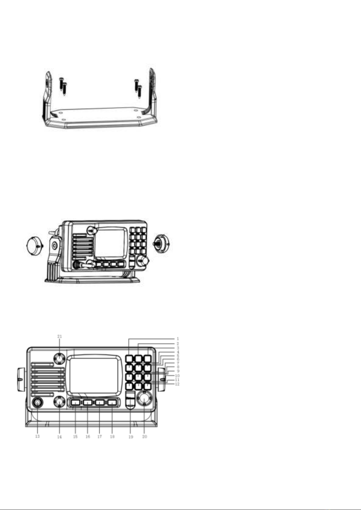
1. Installation
Yoke Mount Installation:
1. Place and fasten the mounting bracket on the
console by 4 screws;
2. Mount the radio onto the bracket;
3. Attach the supplied mounting knobs from two
sides of the bracket to fix the base radio securely
in the mounting bracket (as shown above).
Note. Mounting bracket, mounting knobs and 4
screws M4x20 are in a radio’s package.
2. Front Panel/Back Panel
Front Panel
1. CH/*/WX—short press to enter private channel,
long press to enter weather channel (only
available in US and CAN)
2. Back Light On/Off—short press to back light On/Off.
3. Call/MENU—short press to enter “DSC Menu”, long
press to enter “Main Menu”.
4. 16/9—short press to enter channel 16 or press this
button to quit all other modes and back to the priority
channel quickly, long press will get second-priority
channel 09 or any channel that you’ve set as
second-priority channel.
5. LOC/DX—short press to get conversion between
local and distance mode (DX allows normal receive
sensitivity; and “LOCAL”eliminates receiver noise,
but degrades receiver sensitivity meanwhile
“LOCAL”icon display on LCD).
6. HI/LO—short press to toggle between 25w and 1 watt
output.“HI”or“LO”icon appears on LCD display to
indicate setting.
7. SCAN—short press to enter all scan/all memory scan,
long press to enter priority all/memory scan.
8. MEM—short press to enter memory mode, long press
to save/delete memory channel.
9. DW/FOG—short press to enter Dual Watch Mode,
long press to enter “Foghorn Menu”.
10. GPS/MOB—short press to get GPS activated,Long
press MOB.
11. TRIW/HAIL—short press to enter Tri Watch Mode,
long press to enter “HAILER LISTEN MODE”and
set volume as you wish.
12. UIC/AIS—short press to switch UIC band, long press
to enter AIS (Automatic Identification System)
13. Standard Handset.
14. VOL-The VOL will becomes larger while turning rota
ry knob by clockwise and vice versa.
15. Soft key 1
16. Soft key 2
17. Soft key 3
18. Soft key 4
19. DISTRESS—Pull up key cover and press hold on to
start Distress Alert Calling if you programmed your
radio with an MMSI Number.
20. Power on/off—short press to turn it on, long press to
turn it off. Rotate knob to get up/down function when
radio is on.
21. SQL-The SQL will becomes larger while turning rotar
y knob by clockwise and vice versa. Handset PTT key
—remote command microphone push this key to sent
out radio frequency signals.
5
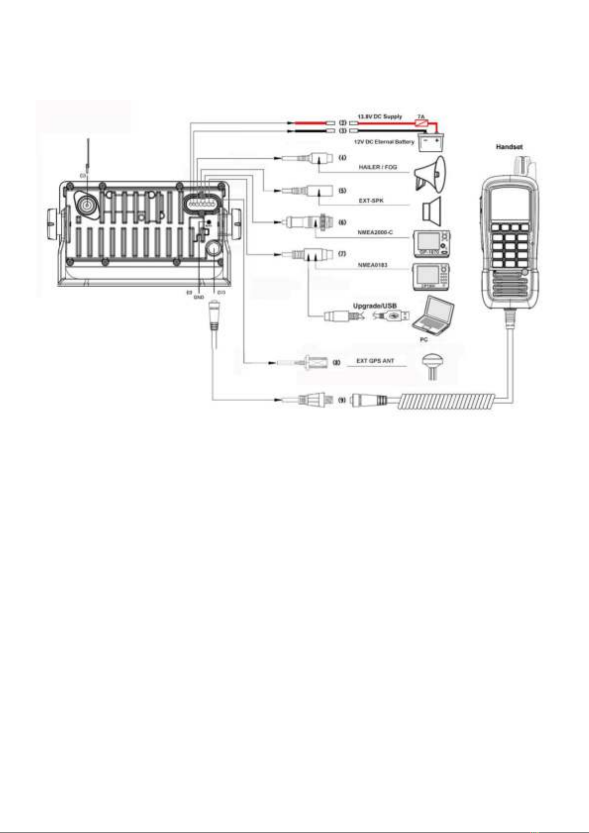
Back Panel
1、RF antenna port SMA (Female)
2、Power + wire (red, 210 mm length)
3、Power –wire (black, 210 mm length)
4、Hailer/Fog cable with 3.5 mm plug (180 mm length)
5、External speaker cable with 3.5 mm plug (180 mm length)
6、NMEA 2000 cable (180 mm length)
7、NMEA 0183 cable/upgrade USB (180 mm length)
8、EXT GPS ANT
9、GND hole (M3x5)
10、The second handset (Optional)
As above show, the “number in picture”correspond to “wiring number”also correspond to “the number in the below table”
The details please check the below table.

6
Connection cables The details please check the below table
Serial
Number
General Description
Function Description
Different Color Code of the cable wires
(1)
RF antenna connector SMA
(Female)
VHF antenna
-
-
(2)
Red & Black Power
Power supply wires
Red
Power+ +13.8V
(3)
Black
Power- GND
(4)
Audio Connector
RCA (Phone) Plug
Hailer/Fog
White
SPK+
Black
SPK-
(5)
Audio Connector Black 3.5
mm Plug
External Speaker
Red
AUDIO-OUT
Black
GND
-
NC
(6)
NMEA 2000 connector
NMEA2000 network
Black
CANH
Red
CANL
(7)
NMEA 0183 connector
NMEA0183 network
Software upgrade
Green
USB-TX
Brown
0183_OUT
White
NC
Orange
0183_IN
Red
USB-RX
BARE WIRE
GND
Black
GND
(8)
EXT GPS ANT connector
EXT GPS ANT
-
-
(9)
GND connection hole
Grounding ware
-
-
(10)
Remote command
microphone connector
(Optional)
Remote command microphone
(Optional)
-
-
Connection cables in a package box
NMEA0183 connection cable, 0.4 m length (depending on a model)
Hailer cable, 0.4 m length

7
3.LCD Display
4. Main Menu Operation on Screen
DSC Menu
Short press the CALL/MENU key will be displayed as
below on LCD:
Detailed entrance for each catalogue as shown below:
DSC Menu
Individual Call
Position Request
All Ship Call
Group Call
Test Call
Receive Call Log
Send Call Log
Phone Book
DSC Setup
My MMSI ID
EXIT ▲▼ENTER
Individual Call►
Individual Call
Receive Call Log►
Receive Call Log
Input Address
Distress Call
From Phone book
Others Call
Position Request►
Position Request
Send Call Log►
Send Call Log
Input Address
Distress Call
From Phone book
MOB Call
Others Call
All Ship Call►
All Ship Call
Safety
Phone Book►
Phone Book
Urgency
Buddy List
Group List
Group Call►
Group Call
Input Address
DSC Setup►
DSC Setup
From Phone book
Position Input
Position Reply
Test Call►
Test Call
Test Ack
Input Address
From Phone book
My MMSI ID►
My MMSI ID
100000008
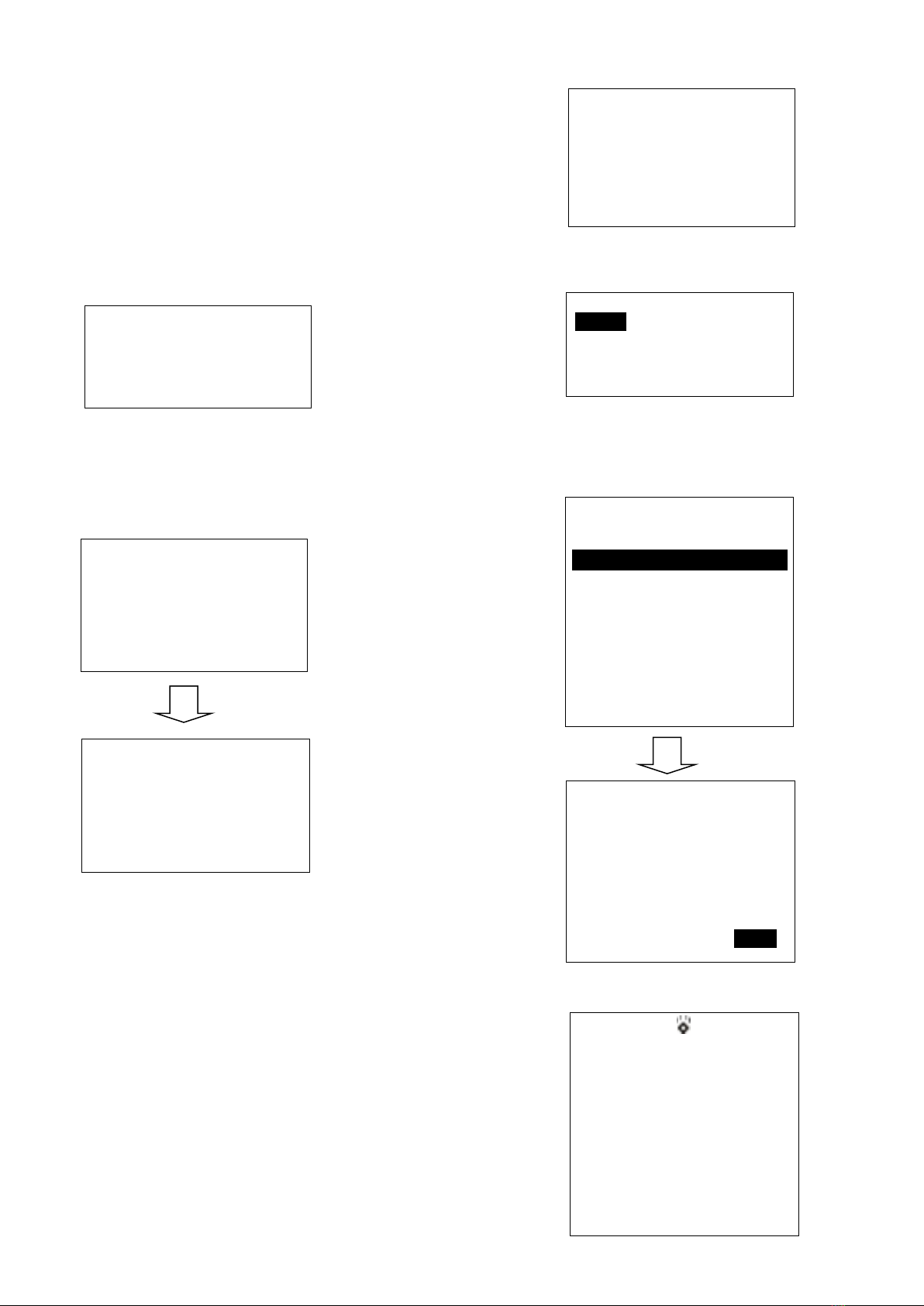
8
MY MMSI ID setup
Firstly, long press CALL/MENU key to enter “Main Menu”.
Secondly, select “DSC Operation”to enter “MY MMSI ID”.
Then you can set up your related MMSI ID as below,
generally you need to double confirm the MMSI ID. Once
confirmed, your MMSI ID will be locked by this radio.
When input 9 digits, UP/DOWN key used for choosing the
number from 1 to 9. You need to input all numbers from the
left to right one by one until all finished. Once fulfilled 9
digits, then press “ENTER”to confirm.
Note. You must enter your user MMSI before you can access
the DSC functions. This is a once-only operation.
Individual Call/Position Request/Group
Call/Test call
Press the “CALL/MENU”key and choose “Individual Call”,
then choose “Input Address”or “From Phonebook”.
Take individual call as example-
First select the “Input Address”, then input 9 MMSI digits
manually such as 123456789 for your address as below:
Then select the type of individual call such as Routine
Next select the preferred channel such as 01 port
operation and confirm to call
Then the individual call is sent as below shown
My MMSI ID
123456789
EXIT
My MMSI ID
Input MMSI
123------
EXIT ▲▼ENTER
My MMSI ID
123456789
EXIT
Input Address
Input 9 digits
0-----------
EXIT ▲▼ENTER
Individual Call
Routine
EXIT ▲▼ENTER
Individual Call
Select Channel:
01 port ops/vts
03 unauthorized
05 port ops/vts
06 inter ship
07 commercial
08 commercial
EXIT ▲▼ENTER
Individual Call
To: 100000000
Safety
Telephony by
Channel 16
EXIT CALL
DSC USA
1W
16
SQL:5
VOL:4 SAFETY
Elapsed 00:56
EXIT
9
All Ship Call
Select the All Ship item The All Ship Call is sent
Re
cei
ve
Ca
ll
Log
When received DSC, you can check those messages from
the “Distress Menu”and see the exact message
Send Call Log
Press
“CALL/MENU”key
to choose “Send Call Log”item and see previous distress
call, MOB call and other call that you have sent.
DSC Menu
Individual Call
Position Request
All Ship Call
Group Call
Test Call
Receive Call Log
Send Call log
Phone Book
DSC Setup
My MMSI ID
EXIT ▲▼ENTER
All Ship Call
Safety
Urgency
EXIT ▲▼ENTER
All Ship Call
To : All Ship
Safety
Telephone by
Channel 16
EXIT CALL
DSC USA
1W
16
SQL:2
VOL:4 DISTRESS
Elapsed 00:04
EXIT
Safety
Select Channel:
01 telephone
02 telephone
03 telephone
04 port ops
05 port ops/vts
06 safety
07 port ops
08 commercial
EXIT ▲▼ENTER
DSC Menu
Individual Call
Position Request
All Ship Call
Group Call
Test Call
Receive Call Log
Send Call Log
Phone Book
DSC Setup
My MMSI ID
EXIT ▲▼ENTER
Receive call log
Distress call
Others call
EXIT ▲▼ENTER
Received DSC
Distress cancel
Undesignated
From: 123456789
GPS POS: Unknown
Time: Unknown
EXIT DELETE

10
Phone Book
Press “CALL/MENU”key to choose “Phone Book”item
and can check the contacted ship by “Buddy List”and
“Group List”
DSC Setup
Main Menu
Long press the CALL/MENU key will display as below:
Detailed entrance for each catalogue as shown below:
DSC Menu
Individual Call
Position Request
All Ship Call
Group Call
Test Call
Receive Call Log
Send Call Log
Phone Book
DSC Setup
My MMSI ID
EXIT ▲▼ENTER
Send Call Log
Distress Call
MOB Call
Others Call
EXIT ▲▼ENTER
DSC Menu
Individual Call
Position Request
All Ship Call
Group Call
Test Call
Receive Call Log
Send Call Log
Phone Book
DSC Setup
My MMSI ID
EXIT ▲▼ENTER
Phone Book
Buddy List
Group List
EXIT ▲▼ENTER
DSC Menu
Individual Call
Position Request
All Ship Call
Group Call
Test Call
Receive Call Log
Send Call Log
Phone Book
DSC Setup
My MMSI ID
EXIT ▲▼ENTER
DSC Setup
Position Input
Position Reply
Test Ack
EXIT ▲▼ENTER
Main Menu
VHF Operation
GPS Setup
AIS Setup
ATIS Operation
DSC Operation
System config
EXIT ▲▼ENTER

11
VHF Operation
Long press the CALL/MENU key to enter “VHF
Operation”item as below for setup:
For priority 2nd Ch, you can select your preferred channel from below as your priority
second channel.
VHF
Operation
Channel Band Set
ATIS Operation
My ATIS ID
Priority 2nd Ch
ATIS Function
GPS Setup
GPS Source
DSC Operation
My MMSI ID
GPS Setting
DSC Function
NMEA0183 Setting
GPS ALARM
System Config
Back Light lumi
Key Beep
AIS Setup
AIS Output
Version Info
AIS Display Set
Factory Reset
AIS ALARM
Language Select
Main Menu
VHF Operation
GPS Setup
AIS Setup
ATIS Operation
DSC Operation
System Config
EXIT ▲▼ENTER
Priority 2nd Ch
Select Channel:
01 telephone
04 port ops
05 Portops/vts
06 safety
07 Port ops
EXIT ▲▼ENTER
VHF Operation
Channel Band Set
Priority 2nd Ch
EXIT ▲▼ENTER
Channel Band Set
USA
√INT
CAN
EXIT ▲▼ENTER

12
GPS Setup
Click the “GPS Setup”to enter “GPS Setup”item for setup as below shown.
Follow like this, you can setup your priority as you wish.
GPS Setup
GPS Source
GPS Setting
NMEA0183 Setting
GPS ALARM
GPS Source
√Built-in GPS
NMEA0183
NMEA2000
GPS Setting
Time Display
Time offset
COG/SOG Display
Speed Unit
NMEA0183 Setting
DSC/DSE Output
GPS Data Output
NMEA0183 Baud
NMEA0183 to N2K Output
Time Display
Disable
√Enable
DSC/DSE Output
Disable
√Enable
GPS Setup
GPS Source
GPS Setting
NMEA0183 Setting
GPS ALARM
GPS ALARM
√Disable
Enable
GPS Setup
GPS Source
GPS Setting
NMEA0183 Setting
GPS ALARM
GPS Setup
GPS Source
GPS Setting
NMEA0183 Setting
GPS ALARM
Main Menu
VHF Operation
GPS Setup
AIS Setup
ATIS Operation
DSC Operation
System Config

13
AIS Setup (Only HM390S)
Long press the CALL/MENU key to enter “AIS Setup”item for setup as below shown
Main Menu
VHF Operation
GPS Setup
AIS Setup
ATIS Operation
DSC Operation
System Config
EXIT ▲▼ENTER
CPA Alarm enable Choose“Disable”or“Enable”item to
enter disable or enable AIS alarm, then press “ENTER”
key to confirm.
CPA Range (Closest point of approach) Alarm distance
setup
Press UP/DOWN key to input digital one by one, after you
have done this, press “ENTER”key to confirm, the
maximum input range is 25.0NM, if the input value over
than 25.0NM, than this operation is invalid, the system will
ask for re-enter, the default CPA value is 1.5NM.
TCPA (Time closest point of approach)Alarm distance
setup
Press UP/DOWN key to input digital one by one, after you
have done this, press “ENTER”key to confirm, the
maximum input range is 30 minutes, if the input value is
over than 30 minutes, the input is invalid, then the system
will ask for re-enter, the default CPA value is 10:00 Min.
ATIS Operation
Long press the CALL/MENU key to enter “ATIS
AIS Setup
AIS Output
AIS Display Set
AIS ALARM
EXIT ▲▼ENTER
AIS Output
All Off
NMEA0183
NMEA2000
√N0183+N2000
EXIT ▲▼ENTER
AIS Display Set
SHIP MMSI
√SHIP Name
EXIT ▲▼ENTER
AIS ALARM
CPA ALARM
CPA Range
TCPA Time
EXIT ▲▼ENTER
CPA ALARM
√Disable
Enable
EXIT ▲▼ENTER
CPA Range
Input Range
03.0NM
EXIT ▲▼ENTER
TCPA Time
Input Time
10:00Min
EXIT ▲▼ENTER

14
Choose to press for setup
or more function as you
wish.
Note. You must enter
your user ATIS ID before you can access the ATIS
functions. This is a once-only operation.
DSC Operation
Long press the CALL/MENU key to enter “DSC
Operation”for setup.
System Config
Long press the CALL/MENU key to enter “system config”
for setup.
Choose to press for setup or more function as you wish.
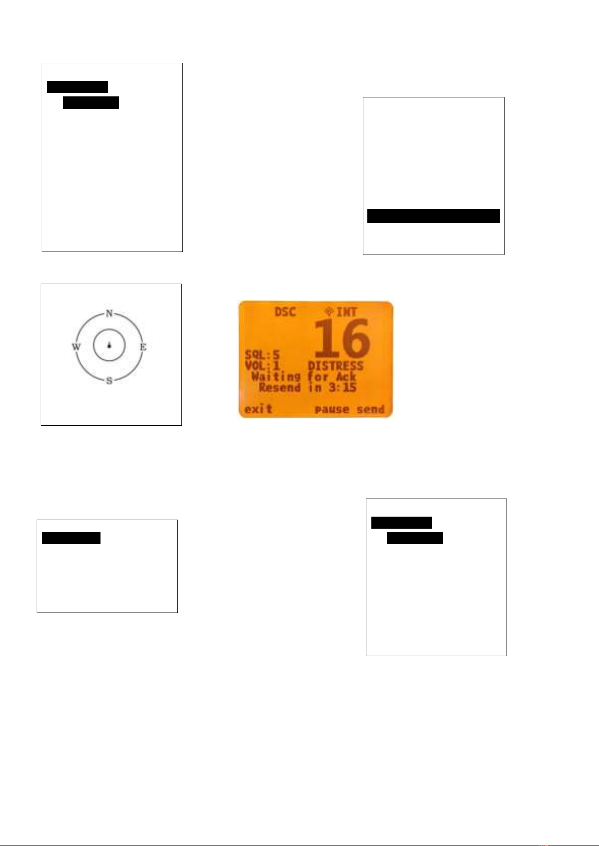
Distress Menu & Send the Distress
Message
Pull the DISTRESS red cover and press the DISTRESS
key. Then below “Distress Menu”will be displayed on
LCD.
Choose one distress
item such as
“sinking”, press and
Main Menu
VHF Operation
GPS Setup
AIS Output
ATIS Operation
DSC Operation
System Config
EXIT ▲▼ENTER
ATIS Operation
My ATIS ID
ATIS Function
EXIT ▲▼ENTER
Main Menu
VHF Operation
GPS Setup
AIS Setup
ATIS Operation
DSC Operation
System Config
EXIT ▲▼ENTER
DSC Operation
My MMSI ID
DSC Function
EXIT ▲▼ENTER
Main Menu
VHF Operation
GPS Setup
AIS Setup
ATIS Operation
DSC Operation
System Config
EXIT ▲▼ENTER
Distress Menu
Undesignated
Fire, Explosion
Flooding
Collision
Grounding
Capsizing
Sinking
Adrift
Abandoning
System Config
Back Light Time
LCD Contrast
Key Beep
Version Info
Factory Reset
Language Select
EXIT ▲▼ENTER
15
hold this for more
than 3 seconds for
transmitting sinking
message out.
You can also choose to resend, pause or exit after
this message was sent.
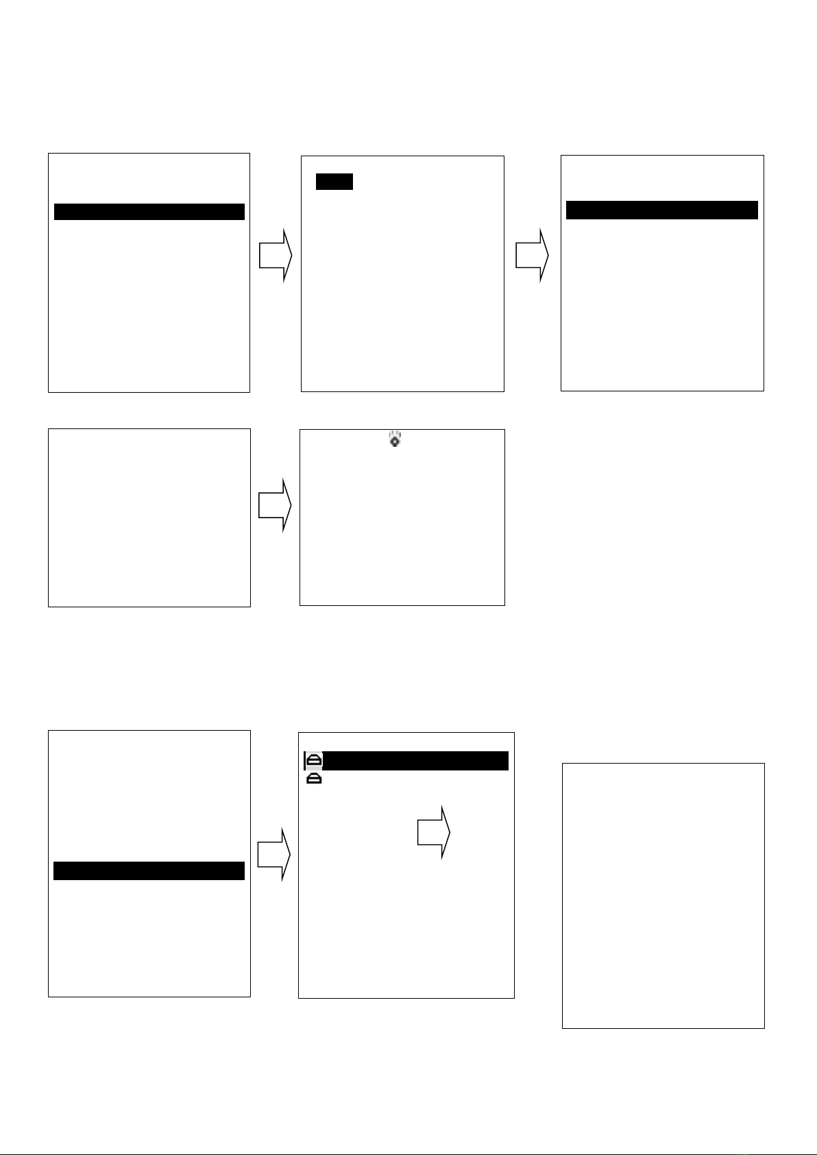
AIS Operation(Only HM390S)
Long press the
‘UIC/AIS’key to
enter this interface.
From the AIS ship info menu, you have three options: List
mode, plotter mode, AIS Alarm list alarm list mode. If you
choose option ‘AIS ship info list’ and press ‘enter’, you
will open the list mode.
If you choose
option ’All
ship plotter’ and
press ‘enter’, you will open the plotter mode.
If you choose option ’AIS Alarm List’ and press
enter, you will open the AIS alarm list mode.
From either mode, you can choose a target with Confirm
key, then press enter to display the target details.
Distress Menu
Undesignated
Fire, Explosion
Flooding
Collision
Grounding
Capsizing
Sinking
EXIT ▲▼
Ship Info menu
Ship info List
Ship plotter
AIS Alarm list
EXIT ▲▼ENTER
NO. MMIS 00/3
00 413903183
233° 0.97nM
01 413997668
213° 1.33nM
02 413401340
277° 1.48nM
03 413454520
280° 1.54nM
04 000000000
237° 3.24nM
EXIT ▲▼ENTER
00/26
3nM
EXIT - + ENTER
NO. MMIS 00/0
00 413903183
233° 0.96nM
01 000000000
237° 5.54nM
02 000000000
265° 1.13nM
03 413401340
277° 1.48nM
EXIT ▲▼ENTER

16
4. Key Operation
Power on/off & rotate to get up/down
function
Short press to turn it on, long press to turn it off. Rotate
knob to get up/down function when radio stay powered on.
Special Function of DISTRESS key &
Real-time DSC
When sending distress message:
Pull the Distress key cover and press the Red key into
“Distress Menu” selection. Select current distress situation
such as “Flooding”, then press and hold for 3 seconds, the
selected DSC message will be sent.
And this message will be resent within 4 minutes--
Press the “PAUSE” key to pause or resume the resend.
Press “SEND” to resend immediately.
Press the soft key below “Exit”icon to exit the current
menu and shortly cancelation option of selected DSC
alerting will be given for confirmation.
When receiving distress message:
The HM390 has two receivers, one receiver used for
receiving/transmit voice and another receiver used to
continually monitor 70 channel. The DSC function of
HM390 is operated in separate way which means any
arriving DSC message will not be ignored even if you are
using HM390 for transmitting or receiving. If you want to
check those messages, please press
“CALL/MENU”to enter “Receive Call Log”for
checking all received DSC messages.
UIC/AIS Control
Short press “UIC/AIS”key and “UIC”icon will be shown
on LCD.
Long press “UIC/AIS”key and enter AIS (Automatic
Identification System) mode (HM390S only). The radio
has built-in AIS receiver to meet the demands for vessels to
know the position, details and navigational intentions of
other vessels within VHF range for improved safety and
collision avoidance.
TRIW/HAIL (Tri Watch/Hailer)
Short press “TRIW/HAIL” key can activate the TRI
WATCH mode. Monitor CH16, current channel and one
programmed channels in cycle.
Long press “TRIW/HAIL”and enter “HAILER LISTEN
MODE”for setup as you wish. Sounds received through
the horn can be heard through the radio speaker. Press and
hold the PTT key and speak your announcement. Release
the PTT key to listen.
GPS/MOB Key
Short press “GPS/MOB”key to get GPS activated
MMIS :413903183
IMO NO:-----
Call Sign:
NAME:YUE HEYUAN
Lat:22°35.733’N
Lon:113°48.922’E
Bearing:232°
Dist:0.96nM
SOG:0.0KIS
COG:225.4°
Rot:-----
EXIT ▲▼ENTER
HAILER
LISTEN MODE
VOL:6
EXIT ▲▼

17
long press “GPS/MOB”key “MOB”icon will be shown on
LCD, then Press Distress for 3 seconds, Distress call with
nature MOB is sent.
MOB mark is outputted via NMEA0183/2000. A MOB
mark is immediately sent to the chart plotter to have a
position as accurate as possible.
DW/ FOG (Dual Watch/Foghorn)
At the normal mode, short press “DW/FOG” key to
activate the DUAL WATCH mode. Monitor the current
channel and CH16 in cycle. Whenever weather alert is
activated, the WX Alert channel will be monitored once
every 4 seconds.
Long press “DW/FOG” key and enter “Foghorn Menu”,
then select preferred item from list. Press PTT key on the
microphone or handset to sound the horn. The horn will
stop when you release the PTT key in Manual Mode .
MEM Key
Enter /Exit the memory mode:
Short press MEM key to enter the memory mode, the
memory channel will be marked and “M” icon show on the
right side next to channel number. At the left side of the
current channel will mark a “MEM “icon which means
already entered the user memory mode.
At the Memory mode, short press the MEM key to exit the
memory mode. The “M” icon and “MEM”icon will
disappear.
Adding/Deleting memory CH:
1. At the normal mode, use the “UP/DOWN” key to select
desired channel for programming.
2. Long press the MEM key to store up the channel as
memory channel.
3. “M” icon will be shown on LCD to indicate the current
CH has been saved in the memory.
4. No limitation for saving memory channels.
5. For USA, International, and Canadian Frequency can be
saved separately.
6. At the normal mode, use the “UP/DOWN” key to select
the memory channel to be deleted.
7. Long press the “MEM” key to delete the selected
channel from the memory mode.
Scan Key
Short press “Scan”key is to activate the scan function
which is searching for currently all working channels.
All scanning: CH1-CH2-CH3-…-CH88
Memory scanning: M1 –M2 –M3 - … M10 –
M1- …
When a signal is detected, the scan pauses until the signal
disappears. Long press the Scan Key, to activate
the Priority Scan.
Priority memory scanning: M1 –CH 16 –M2 –CH 16 - …
CH 16 –M1 …
Priority all scanning:
CH1-CH16-CH2-CH16-CH3-CH16-…..CH88-CH16-L1-C
H16-
Hi/Lo/Lock
Short press the Hi/Lo/LOCK key will toggle the TX power
from Hi to Lo or vice versa. The corresponding “25W/1W”
icon will be displayed on the LCD.
Some of the channels (such as channel 16 initially set for hi
gh power channel13&67 initially set for low power) have
been initially set to be low power or high power, but can be
reprogrammed manually to high power or low power.
Foghorn Menu
Manual mode
Automatic mode
Foghorn Tone Select
EXIT ▲▼
Automatic mode
Engine w/ wandering
Engine w/o wanders
On Vessel
Tug
Towed
Pilot Boat
At anchor
Fishing vessel
EXIT ▲▼
FOGHORN
AUTO MODE
At anchor
VOL:2
EXIT ▲▼ENTER

18
Thus, the software needs to check against the channel
setting stored in the EEPROM long press the Hi/Lo/LOCK
switch lock function
Up/Down Key
At the normal mode, they act as Channel Up/Down key.
When it presses > 0.5 sec, the channels will change in a
quick way. It returns to normal mode when key press is
released.
LOC/DX
Short press to get conversion between local and distance
mode (DX allows normal receive sensitivity; and
“LOCAL”eliminates receiver noise, but degrades receiver
sensitivity meanwhile “LOCAL”icon display on LCD).
16/9 Key
At the normal mode, pressing the 16 / 9 Key (short press to
jump to priority CH16 at High Power and long press to
jump to priority CH9 at High Power) if the current channel
is not the priority channel.
After the channel is tuned to the priority channel, “P-CH”
or “P-2nd” icon is lit to indicate the priority CH16 or CH9
has been reached. UP/Down key functions normally.
Select second priority channel
Solution 1: Select the second priority channel by “16/9”
key: the second priority channel is set as channel 9 by
default. At the normal mode, long press “16/9” key,
“P-2nd” will be displayed as the second priority channel on
LCD, then long press “16/9” key again, “set P-2nd CH”
will be displayed on LCD and the displayed channel will
keep on flashing, then press “UP/Down” key to choose
your preferred channel as new second priority channel.
Finally, long press “16/9” key again to save and confirm it.
Solution 2: Select the second priority channel by
“CALL/Menu” key: long press “CALL/Menu” key to
select “VHF operation” option, and press to select the
“Priority 2nd Ch”, then press and select your preferred
channel by “Up/Down” key and confirm it.
CALL/MENU
Short press to enter “DSC Menu”, long press to enter
“Main Menu”(detailed operation please see 3. Main Menu
Operation on Screen)
Back Light
Short press to switch the Back Light On and Off. Short
Press ‘Backlight’key the light will keep turning on. Press it
again, it’ll turn off. If the backlight setting is off, press any
key will turn on the backlight except the PTT key. The
backlight should be remaining for 5 seconds if no any keys
pressed. The time out will be reset if any key pressed
within the time frame.
CH/*/WX
(WX Channel: Only available for USA, Canada)
A short press of “CH/*/WX” key will trigger Private
channel if there are private channels in memory. Pressing
the “Up/Down” key will change private channel selection.
A long press of “CH/*/WX” key will enter WX mode in
USA or CAN Band. Pressing “Up/Down” key will change
WX channel. The “WX” icon will be displayed on the
screen.
Weather Alert Operation: (USA and CAN Band only)
When in the Weather mode, a long press the “CH/*/WX”
key will switch on the Weather Alert function. Toggling the
Weather Alert function ON/OFF. The icon “WAT” will be
displayed accordingly, When Weather Alert function is
enabled, every 4 seconds the last used weather channel will
be checked for weather alert tone when the radio is tuned
to working channel. With Weather Alert Function enabled,
once the alert tone is detected, the “Weather Alarm” will be
display and alarm sounds. After silencing the weather
alarm, the radio will automatically tune to the current WX
channel where the weather alert has been detected. The
alert will be detected in the modes of Dual/Tri-watch, Scan
operation etc.
6.Other Features and Solutions
Special function keys
if you press and hold the"DISTRESS"Key then power on,
19
you can enter the up grade mode directly. LCD display as
below:
if you press and hold the"PTT"Key then power on, later
you can enter the writing channel mode directly. LCD
display as below:
TX Time Out
The transmission will be automatically turned off after PTT
key pressed over 5 consecutive minutes. The TX mode will
be terminated and back to Rx mode. Once the PTT key is
released, the TX time out timer will be reset. PTT key will
back to work normally.
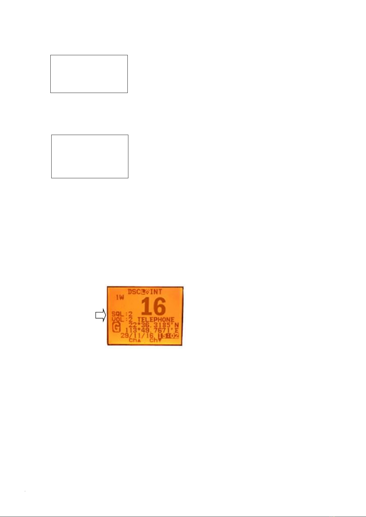
The Local Time & Date on Screen:
UTC time Local time
When HM390 cannot receive the GPS signal to display the
current position, screen will automatic display the time and
date. When radio received the GPS signal, screen will show
the current GPS location, related UTC time and date will
be shown below the GPS location mark.
Long press “Call/Menu”and enter “GPS Setup”to select
the “Time offset”item for setting user’s local time based
on UTC time. Then press “Enter”to confirm. User need to
pass the entire item from hour-minute-second then able to
see enter option to click and confirm.
In other words, the process is the same as your setup of
local time on your computer.
NMEA 0183 and NMEA 2000
The HM390S can be connected to both NMEA0183 and
NMEA2000 networks. When you connect your radio to
a NMEA 0183 network or a NMEA2000 network, the
following data can be transferred; the radio can receive
GPS position. GPS position can be displayed on the
screen and is transmitted with DSC calls. When GPS
data is not present, the radio will signal for you to enter
your position manually every four hours.When the GPS
data does not exist, the radio will signal you to manually
enter a position every four hours.
This setting indicates whether you are connected to a
NMEA 0183 or NMEA 2000 network; the radio can
communicate over two networks at the same time.
The interface used for NMEA0183 is RS232
Compass safe distance is 0.8m
The software’s
Upgrading by PC
Please wait----
The Private
Channels are
Cloning by PC
Please wait---
This manual suits for next models
2
Table of contents
Other Himunication Radio manuals


