Hinton Instruments Z1 User manual

Oldford, Frome, Somerset. BA11 2NN. England • (01373) 451927 • Int: +44 1373 451927
http://www.hinton-instruments.co.uk • [email protected]
Long Haul Converter
Operating Manual
Professional MIDI Management Systems

©1992-2008 Hinton Instruments
All Rights Reserved. Reproduction of any part of this manual in any form is forbidden. This documentation is provided solely to assist Hinton Instruments’
clients achieving better usage of purchased equipment and additional copies will be provided free on request. All documentation, circuit diagrams, panel
layouts, pcb layouts, software and screen layouts are copyright and remain Hinton Instruments’ intellectual property. Disclosure to third parties is forbidden.
MIDIC, MIDIP, MIDIQ, MIDIX, MIDIY, MIDIZ, Z1, Z2, Z4, Long Haul Converter, MIDI Recall, VCA+ and the Hinton Instruments logo are Trademarks or Registered
Trademarks of Hinton Instruments. All other manufacturers’ trademarks are acknowledged.
Contents
Z1 Specification 3
Z1 Installation 4
General/EMC Compliance . . . . . . . . . . . . . . . . . . . . . . 4
Earthing . . . . . . . . . . . . . . . . . . . . . . . . . . . . . . . 5
MIDI Cables . . . . . . . . . . . . . . . . . . . . . . . . . . . . . 5
Long Haul . . . . . . . . . . . . . . . . . . . . . . . . . . . . . . 6
Checking . . . . . . . . . . . . . . . . . . . . . . . . . . . . . . . 7
Mains. . . . . . . . . . . . . . . . . . . . . . . . . . . . . . . . . 7
Front and Back Panel Drawings . . . . . . . . . . . . . . . . . . . 8
In Use . . . . . . . . . . . . . . . . . . . . . . . . . . . . . . . 9
Troubleshooting . . . . . . . . . . . . . . . . . . . . . . . . . . 10
MIDI Implementation Chart . . . . . . . . . . . . . . . . . . . . 11
Z1 Operation 9
Z1 Operating Manual, Revision 1.1 (15 February 2008)

http://www.hinton-instruments.co.uk Page 3
Z1 Operating Manual
This specification and the information presented in this document may change without notice in the interests of continuing product improvement. While every effort is
made to make this document accurate, Hinton Instruments cannot accept any responsibility for the interpretation of the information provided or any liability for any
injury, loss, or damage, direct or consequential, caused by application or inability to use the equipment or information provided.
Z1 Specification
Case
Power
Front Panel
Rear Panel
Electrical
Extruded aluminium case (W: 110 X H: 60 x D: 170 mm).
Stainless steel front and back panels.
85V-250V mains, 50/60Hz. 4W max.
MIDI Connections:
DIN 41524 circular metal twist lock type: In, Thru, Out (x2)
Long Haul Connections:
One XLR3M (output) and one XLR3F (input)
Mains:
IEC fused inlet
Earth:
M4 Bolt
Long Haul Cable Type:
Audio grade screened twisted pair, 80-90 ohms/km.
Maximum Length:
>1000 metres, tested to 100 ohms per conductor.
Output Signal:
0 to +5V max. complimentary @ 31.25kHz.
Delay:
0.5 microseconds @ 100 metres.
11.0 microseconds @ 1000 metres.
Pulse Width Distortion:
< 1.0%

http://www.hinton-instruments.co.uk Page 4
Z1 Operating Manual
Z1 requires a mains power supply with IEC connector on the left hand side. Z1 will work
on a mains voltage in the range of 85V-250V AC, 50 or 60 Hz.
The unit is cooled only by natural convection, so it is necessary to allow adequate space
around the unit to ensure that air flow is not obstructed.
Please take the normal precautions for siting an electronic instrument. Do not place on
a source of direct heat, in direct sunlight, or near another instrument that may result in
interference with either’s operation.
The following statement is provided to comply with FCC regulations in the U.S.A., but
the precautions and corrective measures are applicable worldwide:
Z1 Installation
General
WARNING: This equipment has been tested and found to comply with the limits for a Class A digital device, pursuant
to Part 15 of the FCC Rules. These limits are designed to provide reasonable protection against harmful interference
when the equipment is operated in a commercial environment. This equipment generates, uses and can radiate
radio frequency energy and, if not installed and used in accordance with this instruction manual, may cause harmful
interference to radio communications. Operation of this equipment in a residential area is likely to cause harmful
interference in which case the user will be required to correct the interference at their own expense.
Z1 and its accessories have been tested to exceed the requirements of the above
FCC rules, however this does not guarantee that interference will not occur, especially
if connected to other devices that do not comply with these rules. If interference is
experienced after installation of this equipment turn it off to determine whether it is the
source. If interference is still experienced try to correct the situation by one or more of
the following measures:
• Relocate either Z1 and its associated equipment and cabling or
the equipment affected by the interference.
• Utilise different mains power outlets. Try installing a filter in the mains
lead of Z1 or the other equipment.
• In the case of radio interference where 300 ohm ribbon antennas are
used, try changing to 75 ohm coaxial cable.
If for any reason you should need additional information relating to radio and TV
interference, you may find a booklet prepared by the Federal Communications
Commission helpful: “How to Identify and Resolve Radio/TV Interference Problems”.
This booklet is available from the U.S. Government Printing Office, Washington D.C.
20402, Stock #004-000-00345-4.
This product is fully compliant with the European EMC Directive 89/336/EEC which
applies to apparatus which is “liable to cause electromagnetic disturbance or is itself
liable to be affected by such disturbance”.
Tests performed and passed are: EN50082-1 : 1992, EN55022 : 1994 Class B
This product may contain nuts.

http://www.hinton-instruments.co.uk Page 5
Z1 Operating Manual
Z1 Installation
The case is connected to mains earth and must be grounded for safety. The ground
reference should be provided via the mains inlet or via the chassis terminal in countries
that normally use a two pin mains connector. Do not remove the ground from the mains
connector.
For installations that have separate safety and technical earth systems please consult
with Hinton Instruments before proceeding.
Earthing
WARNING: Failure to observe this practise may result in hazard
to life or damage to connected equipment.
After siting the unit connect all permanent cabling.
Z1 has four MIDI connectors on the front panel: one input, one thru, and two outputs.
Z1 may be inserted transparently in any MIDI connection scheme without any adverse
delay effects.
Connect the MIDI Out(s) to all the MIDI equipment to be controlled. If this is more than
two units, a thru box or a routing matrix should be used rather than daisy chaining via
the MIDI Thrus of each device. Connect the MIDI Out of the source equipment, master
keyboard, etc. to the MIDI In. If there is more than one source of MIDI data, then either a
selector or a routing matrix will be required. If two sources need to be combined a MIDI
data merger will be required. Hinton Instruments also manufactures a comprehensive
range of professional MIDI distribution devices.
The metal DIN connectors on Z1 may be used with twist lock type plugs as well as
the normal type. One MIDI Out should only be connected to one MIDI In, irrespective
of whether it is powered on or not. Use only quality cables intended for MIDI use and
not hi-fi cables. Cable lengths should not exceed 15 metres. Longer cables, including
special long run types, cannot be guaranteed to work in all circumstances as they have
no control over the opto-isolator type used in the receiving equipment, its sensitivity, or
its aging characteristic.
MIDI is an optically isolated system, and the cable screens are connected to the driving
circuitry ground, but not the receiver ground. Do not connect the cable screens to the
plug shells, as this will connect the case ground via the receptacle chassis and may
cause grounding related problems.
MIDI Cables

http://www.hinton-instruments.co.uk Page 6
Z1 Operating Manual
Z1 Installation
The Z1 Long Haul connectors on the rear panel are XLR compatible types intended to
be used with screened, balanced twisted pair audio distribution cabling. The output is
male, the input is female, and pin 1 is connected to the cable screen in compliance with
normal audio practise. It does not matter if you use a pin 2 hot or pin 3 hot convention
as long as the phase is not inverted in the cable run.
The electrical signals used corresponding to a high audio level (5Vdc complimentary
pulses) equivalent to greater than +8dbm and are, of course, at the MIDI baseband
frequency of 31.25kHz.
Long Haul
THIS MAY CAUSE DAMAGE IF CONNECTED TO AUDIO EQUIPMENT
Avoid connection to monitoring systems. High (audio) frequency voice coils are not
designed to withstand continuous high frequency tones. More care should be taken
than when routing SMPTE/EBU Timecode signals.
The Z1 circuitry is optically isolated, similar to the MIDI circuitry, and will drive over one
kilometre of screened balanced cable with a large tolerance to cable and connector
types. It does not require a controlled impedance like many other transmission systems.
The cable screen should be maintained throughout the run and should not be earthed
at any point along the way, e.g. at patchfields. Failure to observe this may result in high
frequency noise being picked up by audio equipment. Also consider that the driver may
be connected to a different phase of the mains from the receiver, or in outside concert
applications to a generator, so it is important not to connect the screen to chassis at
the receiving end.
Otherwise connect in a similar way to MIDI:
• One output drives one input only.
• Do not place phase reversers, attenuators, transformers or active
circuitry in line.
• Avoid connecting two outputs together or to phantom power
supplies. Although the drive circuitry appears to sustain these
conditions it is neither recommended nor guaranteed.
For short runs (over 15m and up to 100m) the Long Haul output may drive MIDI directly
with a suitable adapter cable as shown:

http://www.hinton-instruments.co.uk Page 7
Z1 Operating Manual
Z1 Installation
The limiting factor is the dc resistance of the cable path. Typical cables have a
resistance of 80 to 90 ohms per conductor per kilometre and Z1 is tested to 100 ohms.
If in any doubt, to check a cable path short pins 2 and 3 at one end and measure the
resistance between pins 2 and 3 at the other with a multimeter. Anything up to 200
ohms is acceptable.
Also check that there is no connection to pin 1 with an audio cable tester.
Checking
Z1 is compatible with all worldwide mains voltages and will run on anything between
85V and 250V AC.
Z1 does not have a mains switch. If the unit is not working when connected to mains,
check the mains power supply and the mains fuse within the IEC inlet. The inlet also
contains a spare fuse which should always be a 20mm 2A/250V Quick Acting (F) type.
The fuseholder slides out like a drawer once the mains cable is removed and there is a
spare fuse inside. Remember to replace this if used!
There is a delay of approximately 5 seconds after powering on before long haul
transmission and reception become active. This is deliberate as much MIDI equipment
transmits erroneous data when it is first turned on.
If you experience any difficulty with the above operations or require any further
More reference information and contact details are available on our website: http://
www.hinton-instruments.co.uk.
Mains

http://www.hinton-instruments.co.uk Page 8
Z1 Operating Manual
Z1 Installation
Front Panel Back Panel

http://www.hinton-instruments.co.uk Page 9
Z1 Operating Manual
Z1 Operation
Each Z1 unit contains one MIDI to Long Haul converter and one Long Haul to MIDI
converter. Any MIDI source may be connected to the Z1 MIDI In, converted to Long
Haul, transmitted over audio tie lines up to one kilometre in length, connected to
another Z Series Long Haul Converter, and converted back to MIDI.
Z1 is fully compatible with all past and current models of Hinton Instruments Long Haul
Converters, including MIDIZ, Z2, and Z4.
The front panel has two LED indicators: a red Transmit LED and a green Receive LED.
These display outgoing and incoming Long Haul data. The displays can show individual
MIDI bytes as a brief flash and other types of MIDI data produce characteristic flickering
or various intensity level glows. With a little practice, normal MIDI operation and fault
conditions may be easily recognised. Active Sensing and slow tempo Clocks show as a
dim flicker, MTC shows as a non-flickering glow, and Controller movements and System
Exclusive Blocks as brighter bursts. Remember that Note Offs occur between Note
Ons, so the LEDs may flash at times that do not correspond to perceived sounds.
If an LED stays on at full intensity it usually indicates that a MIDI feedback loop has
been created; usual causes of this problem are routing the output of a merger or
sequencer back to its input.
There is a delay in the signal corresponding to the cable length and is in the order of
11 microseconds for a full kilometre (reduced pro rata for shorter runs). The Long Haul
receiving circuitry reconstitutes the waveform of the original signal so that this is a pure
delay and not a data pulse width distortion like that normally associated with MIDI Thrus
using slow speed opto-couplers. Most MIDI processing devices delay MIDI data in
excess of 400 microseconds so the delays due to Long Haul transmission will not be
perceived or cause any adverse effect.
Z Series Long Haul Converters may be cascaded on a point to point basis to send MIDI
data between MIDI equipment distributed over a wide area.
MIDI or Long Haul connections should not be changed while data is active. This may
cause undesirable results in the receiving equipment as truncated MIDI data tends to
be interpreted as System Real Time codes, e.g. Stop, Active Sensing or Master Reset.
MIDIX routing matrices which use safe switching techniques are recommended to
alleviate this problem.
The Z1 Long Haul circuitry is a proprietary design to a high specification. It is not
RS422, as has been used for similar purposes with mixed results. It is not compatible
with other devices purporting to achieve the same function.
The Long Haul conversion does not effect the MIDI data in any way apart from the very
slight delay. No selective processing is done; either all the data is transmitted or none
at all.
In Use
http://www.hinton-instruments.co.uk Page 10
Z1 Operating Manual
Z1 Operation
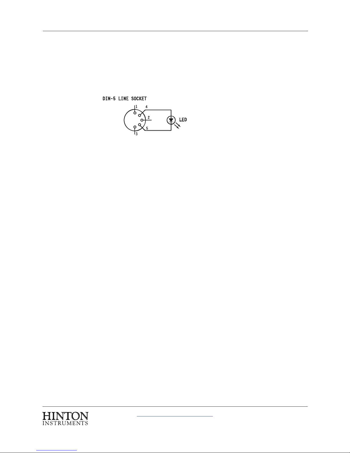
For diagnosing MIDI transmission and distribution related problems we recommend
fitting both a 5 pin DIN plug and a 5 pin DIN line socket with an LED soldered across
pin 4 and 5, with the anode to pin 4, so that the LED body just protrudes through the
cable support.
These testers may be used to check that MIDI data is being transmitted by substituting
them for the receiving equipment. They should not be used in parallel.
Starting with a MIDI source, plug the line plug into its MIDI Out and observe the LED
flicker when MIDI data should be sent. Replace the normal MIDI cable and plug the
line socket into the other end to check that the cable is not faulty. Pin 4 shorted to pin
5 or to the screen will cause this LED to be permanently off, whereas pin 5 shorted to
screen will cause the LED to be fully on.
Work along the MIDI data route until you are sure that data is being presented to the
Z1 MIDI input. Using a short XLR cable connect the Long Haul output back to the Long
Haul input and check that the Receive LED is flickering when data is sent.
When you are satisfied that the Long Haul output is transmitting, follow a similar
process at the receiving unit to the destination MIDI equipment. If the Receive LED
is flickering but the MIDI equipment behaves strangely, this could indicate a phase
inversion in the XLR cabling. Otherwise, check that the MIDI equipment is set up for
transmitting and receiving on the same MIDI Channel and that the relevant Modes and
Status types are enabled.
The Z1 Long Haul Converter should give years of fault free operation—many Hinton
Instruments Long Haul Converters have been in continuous use for over ten years or
used on major international tours and events—but it has been designed for ease of
servicing in the event of any component failure.
Spare components and sub assemblies are available for critical maintenance
applications. Please enquire if you need this support.
Troubleshooting
%*/-*/&40$,&5
-&%

http://www.hinton-instruments.co.uk Page 11
Z1 Operating Manual
Z1 Operation
MIDI Implementation Chart
O : Yes
X : No
Notes: 1. Every MIDI Byte is passed without processing.
Function Transmitted Recognised Remarks
Basic Channel Default
Changed
1-16
1-16
X
X
Mode Default
Messages
Altered
O O
Note Number True Voice O O * Note 1
Velocity Note On
Note Off
O
O
O
O
* Note 1
* Note 1
Aftertouch Key
Channel
O
O
O
O
* Note 1
* Note 1
Pitch Bend O O * Note 1
Control Change O O * Note 1
Program Change O O * Note 1
System Exclusive O O * Note 1
System Common MTC
Song Position
Song Select
Tune
O
O
O
O
O
O
O
O
* Note 1
* Note 1
* Note 1
* Note 1
System Real Time Clock
Commands
O
O
O
O
* Note 1
* Note 1
Aux Messages Local ON/OFF
All Notes Off
Active Sense
Reset
O
O
O
O
O
O
O
O
* Note 1
* Note 1
* Note 1
Table of contents
Popular Media Converter manuals by other brands

CHD Elektroservis
CHD Elektroservis 8-443 user manual

Siemens
Siemens SINAMICS G110M Original instructions

Optocore
Optocore FESTIVAL BOX PETIT operating manual

Hengstler
Hengstler AR 60 Series installation instructions

Cabletron Systems
Cabletron Systems EMC39-12 user guide

Matrox
Matrox MXO Installation and user guide


Z3 Technology
Z3 Technology HE4K-DCK-1X User instructions

EGO SYS
EGO SYS Miditerminal 4140 user manual

TRENDnet
TRENDnet TFC-110S15I - Media Converter - External Specifications

TELELYNX
TELELYNX IDH-9001 user guide

Extron electronics
Extron electronics SMD 101 user guide

Extron electronics
Extron electronics mediaport 200 user guide