Warranty
Warranty malfunctions occurring under conditions of normal use in conformity
with the Instruction Manual and Product Precautionary Markings will be
repaired free of charge. This warranty is valid for a period of one (1) year from
the date of purchase. Please contact the distributor from which you pur-
chased the product for further information on warranty provisions.
Introduction
Thank you for purchasing the HIOKI Model PW9000/PW9001 Wiring Adapter.
To obtain maximum performance from the device, please read this manual
first, and keep it handy for future reference.
The Wiring Adapter are specially designed to facilitate connections
to three-phase 3- and 4-wire systems using the PQ3198 Power Quality Ana-
lyzer. It can also be used with the PW3390 Power Analyzer.
For more information about safety precautions and maintenance service, refer
to the instruction manual for the device to which you plan to connect the wiring
adapter.
For connection to the PW3390, see the PW3390 Instruction Manual.
Specifications
Product warranty
period 1 year
Operating
environment Indoors, pollution degree 2, up to 2000 m ASL
Storage temperature
and humidity
-10°C to 50°C (14°F to 122°F), 80% RH or less
(non-condensing)
Operating tempera-
ture and humidity
-20°C to 50°C (-4°F to 122°F), 80% RH or less
(non-condensing)
Maximum input
voltage
PW9000: 1000 V (between A and B, B and C, C and A)
PW9001: 1000 V (between A and N, B and N, C and N)
1740 V (between A and B, B and C, C and A
Maximum rated volt-
age to earth
1000 V, Measurement category III
(anticipated transient overvoltage 8000 V)
600 V, Measurement category IV
(anticipated transient overvoltage 8000 V)
Maximum rated
current 1 A
Dielectric strength 6.880 kVrmsAC (50/60Hz, current sensitivity 1 mA)
(Between voltage input terminals and case)
Applicable standard EN 61010, A type
Dimensions Approx. 125W×80H×32D mm (4.92”W×3.15”H×1.26”D)
(Cable length: Approx. 152 mm (5.98”))
Mass Approx. 190 g (6.7 oz.)
Overview
PW9000, PW9001
WIRING ADAPTER
Instruction Manual
EN
May 2020 Revised edition 3
PW9000A980-03 20-05H
PW9000
Wiring Adapter
For three-phase 3-wire (3P3W3M)
Only three voltage cords need to be connected to the cir-
cuit, instead of six.
PW9001
Wiring Adapter
For three-phase 4-wire (3P4W)
Only four voltage cords need to be connected to the cir-
cuit, instead of six.
Before Use
Indicates cautions and hazards. When the symbol is printed on
the instrument, refer to a corresponding topic in the Instruction
Manual.
Indicates an imminently hazardous situation that will result in
death of or serious injury to the operator.
Indicates a potentially hazardous situation that may result in
minor or moderate injury to the operator or damage to the device
or malfunction.
To prevent an electric shock accident, confirm that the white or red
portion (insulation layer) inside the cable is not exposed. If a color
inside the cable is exposed, do not use the cable.
Connecting a Wiring Adapter
• Do not exceed the maximum input voltage during measure-
ment. Doing so may damage the adapter or cause injury.
• The maximum terminal-to-ground rated voltage is 1,000 V
(Cat III) or 600 V (Cat IV). Do not exceed these voltages rela-
tive to ground during measurement. Doing so may damage
the adapter or cause injury.
• The maximum input voltage and maximum terminal-to-
ground rated voltage depend on the connected device.
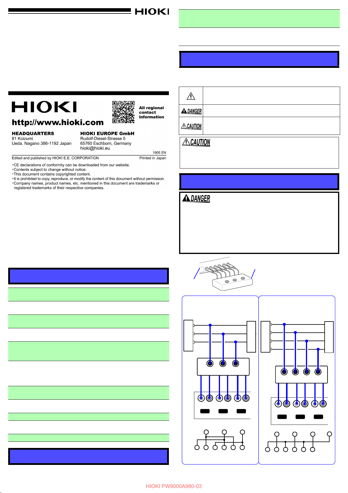
PQ3198
PW9000
Connect all 6 output pins on the
wiring adapter to the voltage input
terminals on the device to which it
is being connected. Insert plugs all
the way in.
Example:
A
B
C
U- U+ U- U+ U- U+
U INPUT
CH1 CH2 CH3 CH
LOAD
Blue
A, B, C: Line
Yellow
Red
SOURCE
ABC
Blue
Yellow
Red
Black
Black
Black
Three-phase 3-wire (3P3W3M)
U- U+ U- U+ U- U+
U INPUT
CH1 CH2 CH3 CH
A
B
C
Red
N
Blue
Black
Yellow
SOURCE
LOAD
A, B, C: Line
N: Neutral
ABCN
Blue
Yellow
Red
Black
Black
Black
Three-phase 4-wire (3P4W)
U- U+ U- U+ U- U+
CH1 CH2 CH3
ABC
N
U- U+ U- U+ U- U+
CH1 CH2 CH3
AB
C
PW9001 Wiring Adapter
PW9000 Wiring Adapter


