HIOS Neji Taro III HS III-10 User manual

Automatic Screw Feeder
Neji Taro
HS series
HS -10 HS -12 HS -14 HS -17
HS -20 HS -23 HS -26 HS -30
Instruction Manual
Readthismanualbeforeusingthisdevice.
CurrentasofSeptember2018
18B
No. ET-D004
HIOS Inc.
1-16-5 Akiyama, Matsudo City, Chiba Pref., Japan
TEL: +81-47-392-2001 FAX: +81-47-392-7773

-2-
CONTENTS
1) BEFOREUSE......................................................................................................................................................1
2) FORSAFEUSE..................................................................................................................................................1
3) NAMEOFMACHINEPARTS........................................................................................................................3
4) ADJUSTMENTSANDCHECKSBEFOREUSE..........................................................................................4
5) OPERATINGINSTRUCTIONS.................................................................................................................... 12
6) REPLACEMENTOFCONSUMABLEPARTS.......................................................................................... 13
7) TROUBLESHOOTING.................................................................................................................................. 18
8) SPECIFICATIONS........................................................................................................................................... 23
9) EXTERNALDIMENSIONS........................................................................................................................... 25
10) THEFOLLOWINGTABLEISFORCHINARoHS2................................................................................ 26
Cautions
Besuretofollowthecautions,oritcouldlead
toseriousdamage,suchasinjuries,electric
shock,anddamageproperties.

-1-
1) BEFORE USE
ThankyouverymuchforselectingourAutomaticScrewFeeder“HSIIIseries”.Pleasecheckthefollowingaccessoriesbefore
operatingthemachine.
•CD-ROM,1
•ACadapter,1piece
•Hexagonalwrench,1piece
•Screwdriver,1piece
*ForfeedermachinespurchasedoutsideofJapan,noadaptorwillbesuppliedwiththefeeder.
Pleasepurchaseaseparateadapterwithequivalentoutputspecicationasrequired.
2) FOR SAFE USE
ReadthefollowingCautionsthoroughlyforthesafeuseofthismachine.Keeptheminmindduringtheoperationofthemachine
inordertopreventinjuriesanddamagetoproperty.
Installation
Caution:InstallationInstallthemachineonalevel,stablelocationthatcanendureit’sweightandrunningconditions.Ifthe
machinefallsdownorturnsoverduetoimproperinstallation,injuriesorpropertydamagemayoccur.
OperatingEnvironment
Caution:Donotoperatethismachinewhereflammableorcorrosivegasispresent.Itisextremelydangeroustousethis
machineundersuchcircumstances.Donotoperatethismachineinenvironmentofhighhumidity.
ACadapter
ForfeedermachinespurchasedoutsideofJapan,noadaptorwillbesuppliedwiththefeeder.Pleasepurchaseseparateadapter
withequivalentoutputspecicationasrequired.

-2-
Thetransformer-typeACadapterattachedtothemachinehasnominaloutputofDC12V-500mA;duringapplication,itisdesigned
tosupply an average output atabout15Vtothescrewfeeder.Inthecasewhereadierenttype of adapter or externalpower
sourceisused,itisrecommendedtousea15Vswitchingtypeadapter,orregulatedpowersupplywhichcanprovideconstant
outputat15V.
Rail
Caution:Donotdamagenoroiltherail.
Screwcompatibility
Caution:Donotusescrewswithgrease,dirtyscrewsoranyscrewotherthanthoseprescribed.
Accessofscrews
Caution:Donotexertexcessiveorimpactiveforcewhenaccessingthescrews.
Whenmachineisnotinuse
Caution:BesuretounplugtheACadapterfromthewalloutletduringclosinghoursandifthemachinewillbeleftunattended
foranyextendedperiodoftime.
Abnormalitiesduringoperation
Caution:Stopoperationandunplugimmediatelywheneveryousenseabnormalitiesorunusualmachinebehaviorsduringthe
operationofthismachine,suchasapungentodor.TurnothepowerswitchanddisconnecttheACadapterfromthe
receptacle.Continued operation may cause re,electricshock,malfunctionorpersonalinjury.Immediatelycontact
thedealerfromwhichyoupurchasedtheproduct.
Servicing
Caution:Donotattempttorepair,disassembleormodifythismachineexceptwherespeciedbythismanual.
Consultyourdealerforserviceandrepairofthismachine.
-3-
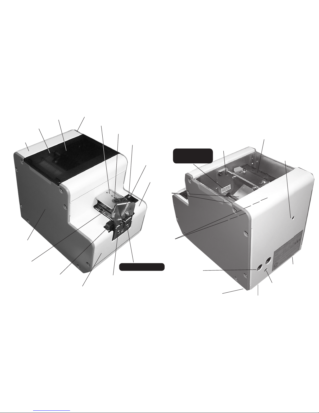
3) NAMES OF MACHINE PARTS
Rightsidecover
Bitguideassembly
Railxingbolt
Powerswitch
Bitguide
Light-receiving
sensor
Railassembly
Frontcover
Light-emittingsensor
Holdingplate
Leftsidecover
Rearcover
Uppercover
Scoopingchamber
Scooping
chamber
Passingplate
Brush
Timerknob
Tiltingbolt(under
themachine)
Vibrationadjusting
platexingbolt
Vibrationadjustingbolt
(underthemachine)
Tiltingbolt
(underthemachine)
DCjack
Scoopingblock
(leftandright)
(movingupanddown)
Passingplate
indenticationseal
Railidenticationseal
-4-
4) ADJUSTMENTS AND CHECKS BEFORE USE
Beforeusingthemachine,pleasecheckiftherailandcomponentsinstalledonthemachineissuitableforthescrewapplied.Therailisφ1.0
toφ 3.0dependingonthenominaldiameter.Itisdeterminedbytheidenticationsealonarailfrontcover.Therearetwokindsofpassage
plates,namelyoneforφ1.0toφ1.7andoneforφ2.0toφ3.0.Itisdeterminedbyanidenticationsealaxedonapassageplate.
◆ When there is no rail installed on the machine, please install the rail before use.
First,unfastentherailxingboltthroughtheupperbitguideholder.
Inserttherailintothefurthestpoint.
Fastenthexingbot.
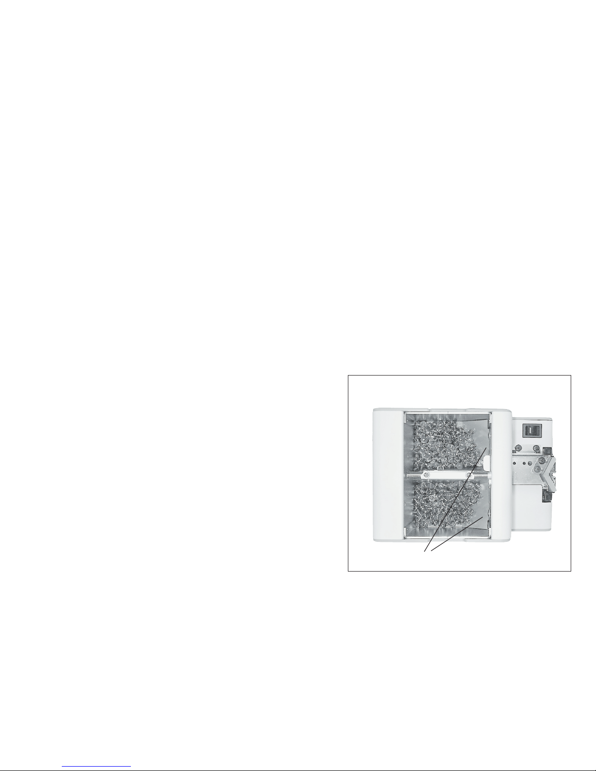
◆ Quantity of screws thrown in
Iftoomanyscrewsarethrownin,orientationandtransferofthe
screwswillbeseriouslyaected.Seethediagramontherightforthe
maximumnumberofthethrowscrewsinthe[scoopingchamber].
•Setthe[scoopingblock]inthelowestpossibleposition.
•
Throwinscrewsuptoapositionof2mmto3mmbelowtherailgrooveface.
•Inthiscondition,ensurethatthefrontinclined-faceoftherampis
nothiddenbythescrews.
Thesepartsoftheinclinedfaceoftherampshouldbeuseunderline.
Ensurethattherailgroovefaceisnothiddenbythescrews.
(Screwsshouldbepositioned2to3mmbelowtherailgroove.)

-5-
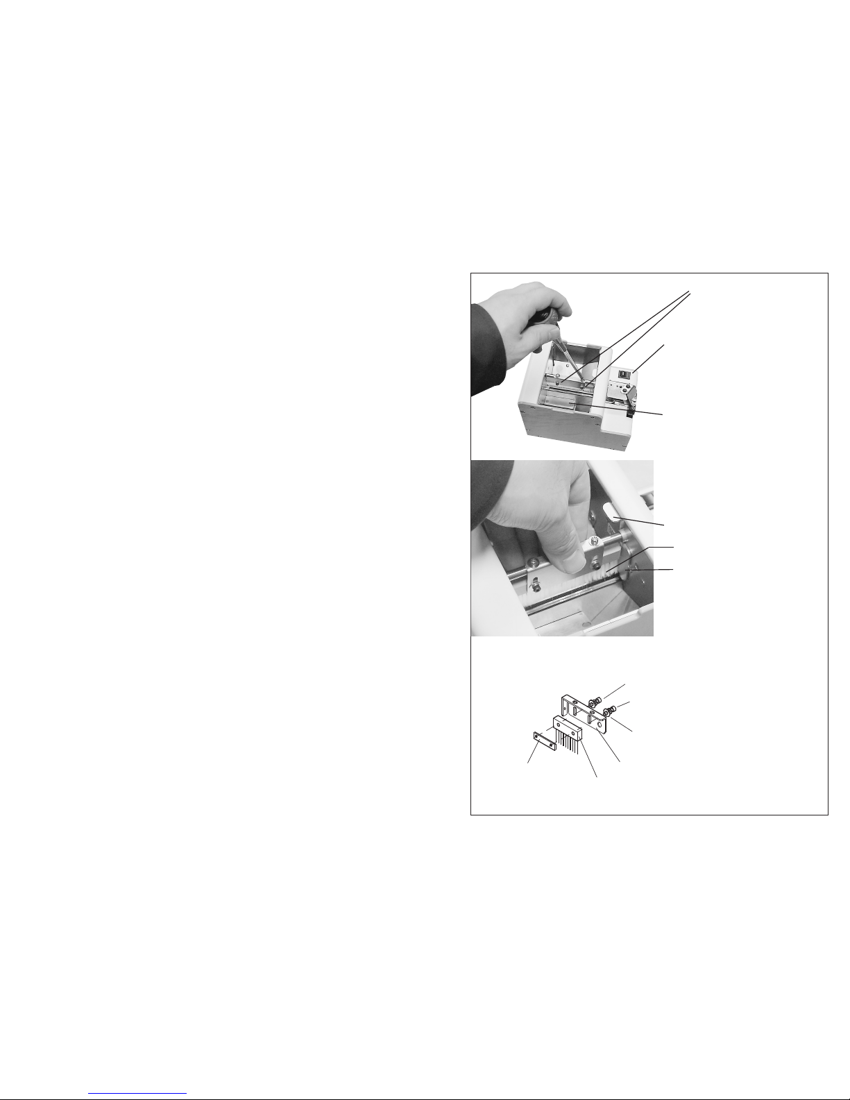
◆ Adjustment of the brush
Checktheheightofthebrush.
•Asinthepictureontheright,setthebrushtoanapproximatelylevel
position.
•Ensurethattheedgeofthebrushisgrazingthescrew’shead.
•Iftheheightofthebrushiseithertoolowortoohigh,orientation
andtransferofthescrewswillbeseriouslyaected.
•Ifadjustmentisnecessary,adjustitbylooseningthebrushheight
adjustingscrew.
Ensurethattheedgeofthebrush
isgrazingthescrew'shead.
Adjustmentscrew
forthebrush
Brush
Screws
Turnthepowerswitchon
&o,andsetthebrushon
thelevel.

-6-
Thegapbetweentheholdingplateandtheheadof
screwsshouldbe0.2mmto1mm.Theholdingplateand
therailshouldbeparallel,too.
Thebitguidebracketattachingscrews
Adjustmentof
theheight
Matchthecenterofthe
holdingplateoutletand
therail.(Itisnotnecessary
toremovethebitguide.)
Attachingscrews
◆ Adjustment of the holding plate
Checkthepositionoftheholdingplate.
•ensurethatthegapbetweentheheadoftheusedscrewintherail
grooveandtheholdingplateisapproximately0.2mmto1mm.
•Ifthereisnogap,thescrewgetscaught.Ifthegapistoolarge,the
screwoverlapsorjutsout.
•Ifadjustmentisnecessary,adjustitupordownbylooseningthebit
guidebracketattachingscrew.
Easily adjust it by using the 0.35 mm gauge plate.
Loosenthebitguidebracketattachingscrew.Insertthegauge
betweenscrewsontherailandtheholdingplate.Tightenthebit
guidebracketattachingscrewwhentheholdingplateistouchingthe
frontandthebackofthegaugeequally.
Caution:Matchingthecenteroftheholdingplateoutletandtherail
centermaybenecessary.
•Ensurethatthecenteroftheholdingplateoutletmatchestherail
center.
•Ifnot,adjustitbylooseningtheattachingscrew.
Holdingplate
-7-
◆ Adjustment of the passage plate
Checktheheightofthepassageplate.
•Ensurethatthepassageplateisadjustedataheightwheretheused
screwcanmanagetopass.
•Ifthepassageplateistoolow,thescrewcannotpass,andiftoo
high,thescreweasilygetscaught.
•Ifadjustmentisnecessary,adjustitbylooseningthepassageplate
attachingscrew.
Caution:Slidethehalfblankingatbothsidesofthepassageplateup
anddowntheguide.
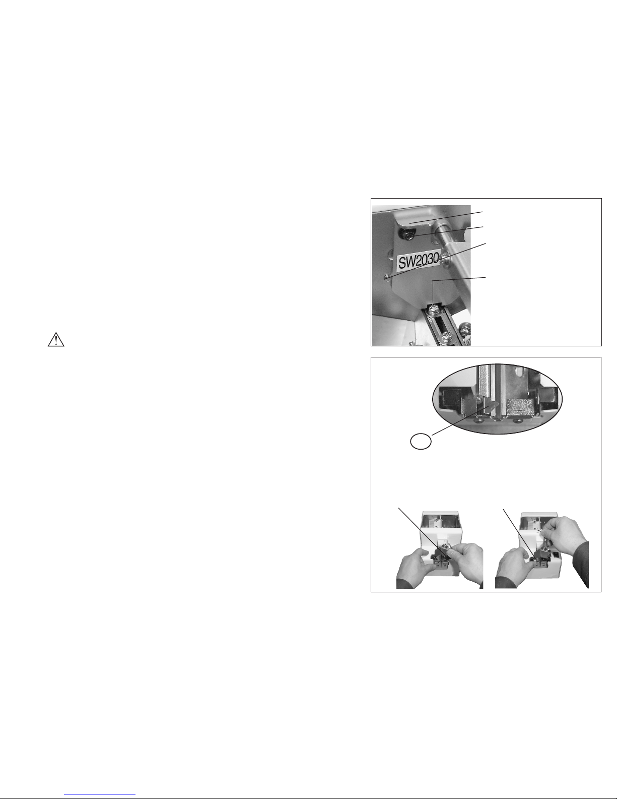
◆ Adjustment of the rail
Checkthephysicalrelationshipofthestopperandsensor.
•ensurethattherailisxedsothat“A”portionofthestopperis0mm
to0.5mmaheadofthesensoropticalaxis.
•Ifadjustmentisnecessary,adjustthelocationbylooseningtherail
attachingscrew.
Ensurethescrewpasses
throughthewindowwithno
extraspace.
Screw
Passageplate
Passageplateattachingscrew
Halfwayhole
(Onbothsidesofthepassage
plate)
Lookingdownfromthetop,aportionofthestopperis
stickingout0to0.5mmmoreforwardthanthesensor's
opticalaxis.(It'snotnecessarytoremovethebitguide.)
Adjusttherailbackandforth.
A
Loosentherailattachingscrew.

-8-
◆ Check/adjustment of the bit guide
Checkthepositionofthebitguide.
•
Adjustthebitguidetoapositionwhereausercaneasilytakescrews.
Actuallypickupscrewsafewtimestoadjustit.
Adjustitbylooseningtheattachingscrews.
Caution:Therailisadjustedaccordingtothephysicalrelationship
withthesensorasontheprecedingpage,sobasicallythe
railisnotadjustedhere.
◆ Adjustment of the left and right guide pieces
Pleasecheckandadjustpositionoftheguidepieceasnecessary.
Thebitguideisoriginallysetatapproximately3mmatthefront
opening,andshallbeadjustedasneededbytheuser.
•Unfastenthefrontxingscrews,insertdriver-bittobeusedand
adjusttheslitopening,sothatthebitcanmovefreely.
•Aftertheadjustment,trytopickupascrewandcheckitsworking
conditionbeforeturningonthepower.
◆ Check/adjustment of rail vibration
Transferspeedsofscrewsdieraccordingtoscrewtype.
Thismachinecanchangerailamplitudeandadjustthetransferspeed.
•Toadjustamplitude,loosenanamplitudexingscrewattherear
ofthismachineandturntheamplitudeadjustingscrewatthe
bottomofthemachine.
•Toadjustamplitude,loosenanamplitudexingscrewattherear
ofthismachineandturntheamplitudeadjustingscrewatthe
bottomofthemachine.
Thebitguideattachingscrew
Bitguide
Screw
(Assy.attachingscreews)
Adjustment
Amplitudexingscrew
LargerVibration
Amplitude(Vibration)
adjustmentscrew
SmallerVibration
-9-
Viewingitfromthebottom,ifturnedclockwise,theamplitudebecomeslarger,andifturnedcounterclockwise,theamplitudebecomes
smaller.
•Ifyoumaketheamplitudetoolargeinordertospeedupthetransfer,itmaybecomediculttopullupscrews.So,adjustit
toappropriateamplitudeforthetypeofscrewbeingused.
•Afteradjustmentiscompleted,besuretotightentheamplitudexingscrewontherearofthemachine.
◆ Adjustment of the tilting bolts
Astheoriginalsetting,theautomaticscrewfeedershallbe
horizontalwhensetonasurface.
Dependingonspecictypeofscrewapplied,theremaybecases
thatthescrewscannotmovesmoothly.Atsuchinstance,please
checkthe“Adjustmentoftherail”sectionlistedinthisoperation
booklet,oradjusttiltingangleofthemachineasnecessary.
•Thetiltingboltsarelocatedonbottomrearendofthe
machine.
•Whentheseboltsareused,theyshallbesetatthesame
heightandangleonbothsides.
•Sincetheboltsdonothavestoppersequippedinside,please
becarefulnottodetachthemfromthemachinebody.
•Aftertheadjustment,pleaseverifyifscrewdeliveryfunctions
properlybeforeapplication.
Tiltingbolt
• Loosenthetiltingbolts,toadjustangleof
themachine.
• Keepbothsidesasthesameheight.

-10-
◆ Check of the sensor’s optical axis
Ifthereisnoscrewatthestoppersection,thismachinecontinuesoperation,andiftherearescrews,itstopsafteracertainperiodoftime
haspassed.Thismachinehasthelevelofthescrew/noscrewsensoradjustedbythereferencerailonshipment.Inreality,however,alevel
adjustmentofthesensormaybecomenecessarywhenusingthin-headscrewsorduetooccurrenceofthevariationonrailreplacement.
Then,followthedirections(1)and(2)fortheadjustment.
(1) •Loosethesensorattachingscrewonthesidelitupasmuchasitmovesbypickingupthesensorholderwithngers,and
turnonthepowerswitch.
•Placeascrewonthefailwithinthesensorrange.
•Holdtherailendlightlywithngersasmuchasitdoesn’tvibratesothatscrewsdoesn’tpassthrough.
•Whenthesensorholderismovedupanddown,thereisapositionthesensorofthereceivinglightsidedefectsascrewhead
andstopsthevibration.Tightthesensorattachingscrewatthisposition.
•Conrmwhetheritreallyworks or not. See ifascrewpasses
throughandthesensordetectsifandstops.
(2) •Removethemachinebodyrearcover,andmeasurethe
voltagelevel.AdjusttheIC40507th-pinvoltagelevel.The
ground,whenmeasuringit,isthebody’smetalpart.
•
Adjustmentisnotnecessaryifthevoltageleveliswithin0.25to
1.5Vwhenarailisandifthereisnoscrewatthestoppersection.
•Whenadjustmentisnecessary,loosenthesensorattaching
screwontheside.Adjustthevoltagelevelbymovingitup
anddown.(Itiseasiertomakeanadjustmentifconnectorof
themainmotorisremoved.)
•Aftertheadjustment,throwinthescrewsandrunitpractically
inordertochecktheoperation.
Note:Whennoloadedscrewsare:0.25Vto1.5VWhenloaded
screwsare:3.5Vormore.
Adjustingthesensorattachment
upanddownonthesidelitup
Thesensorattaching
screwonthesidelitup
No.7pinofIC4050

-11-
◆ Adjustment and Check of the timer
Thespeedofscrewdeliverydependsontheactualkindofscrew.Byadjusting
thetimerofthemachinethescrewsarepickedupsmoothly.
•Ifascrewispickeduponthestopperandthescrewcomingnextisnot
pickedupforacertainamountoftime,theunitstopstheoperation.Then
ifyoupickupthescrew,itstartsoperatingagain.Youcanchangethetime
byadjustingthetimerwithin1to6seconds.
•Timechangesafteradjustingthetimessettingvolumeontherearofthe
machineasshownontheright.Viewingtheunitfromtheback,ifit’sturned
clockwise,thetimebecomeslonger,andifit’sturnedcounterclockwise,the
timebecomesshorter.
•Donotuseexcessiveforcewhilemakinganadjustment.Turnitonlyas
muchasthepossiblerotatingrangeallows.
Caution:Usethescrewdriverprovidedwiththemachine.Usingother
screwdriversmaydamagecircuitcomponents.
◆ The operation check of the overload protection circuit
Foroverloaddetectionandcheckofprotectioncircuits:Trytoforcethe
movementofthescoopingblocktostop,tochecktheoperationofoverload
detectionandoverloadprotectioncircuits.Ifyouforcethemovementofthe
scoopingblock to stop for about4.5secondsorless,themainmotorstops
afterrepeatingrotationsofreverse->forward->reverse->.
Tocanceltheaboveoperationalcheck,turnoandthenturnonthepower
switchagain.
Checkoverloaddetectionandprotection
circuitsbyforcingtheup-and-down
movementofthescoopingblocktostop.
Timersettingvolume
Toreducetime
Toincreasetime

-12-
5) OPERATING INSTRUCTIONS
◆ Supplying screws (Refer to P. 4)
•Setthe[scoopingblock]tothelowestpossibleposition.Removethetopcoverofthe[scoopingchamber].Throwinscrews
uptoapositionof2mmto3mmbelowtherailgroovetopface.
•Inthiscondition,ensurethatthefrontinclined-faceoftherampisnothiddenbythescrews.
Caution:Anexcessivequantityofscrewsthrowninmaycauseamachinemalfunction.
◆ Switch-on
•PlugtheprovidedACadapterintoawalloutletandintothemachine.
•Turnonthepowerswitch.Thepowerswitchlampwilllightup.
•Theup-and-downmovementofthescoopingblockandback-and-forthmovementoftherailwillactivate.
•Subsequently,screwsaresuccessivelysenttotheoutletdirection.Unlessyoupickupthescrewsinthestoppersection,the
sensorsensesitandthemachinestopsoperation.
•Ifyoupickupthescrewsinthestoppersection,thesensorsensesitandthemachineresumesoperation.
◆ Picking up screws
•Whenpickingscrewsup,useabitthattsthescrewdiameterandgroovewidthoftheholdingplate.
•Makeamotor-drivendriver’sbitupright,putitdowntotheverticaldirectionalongtheVgrooveofthebitguidewhile
turningit,andpullitouttowardyourselfwhencrossrecessonthescrewhead.
Caution:Donotexertanyexcessiveforcetotherailatthistime.Itmaycausethemachinetomalfunction.
◆ Timer settings (Refer to P. 11)
•Ifyoupickupscrewsofthestoppersectionandthendonotpullupthenextscrewsforacertainperiodoftime,themachine
stops.Operationwillresumeagainafteryoupickupscrews.
•
Thetimeuntilthemachinestopsisadjustablewithin1to6seconds.Adjustitaccordingtotheprocedureinthediagramontheright.
Caution:AlwaysunplugtheACadapterfromthewalloutletbeforemakinganyadjustmentstoavoidinjury.
-13-
6) REPLACEMENT OF CONSUMABLE PARTS
Replacement of brushes
• Ifthetipofthebrushwearsoutanddoesnotwipeoascrew
fromanabnormalposition,replaceitwithanewbrush.
• Turnthemachine’spowerswitchonandoffandpositionthe
brushasinthediagramontheright.(PositionitsothattheBrush
assemblymountingscrewscanbeeasilyremoved.)
• Afterreassembly,ensurethatthebrushandthepassageplatedo
notclashwhentheBrushassemblymoves.Thegapisideally“0” .
• RefertoP.5,“Check/adjustmentofthebrush”formounting
adjustments.
Part number of brush assembly:
• HS3-02053
Brushassembly
attachingscrew
Brushassembly
Whenthebrushis
operating,itshouldnot
comeincontactwiththe
passingplate.
Powerswitch
Passingplate
Brush
Brushbracket#2
Brush
Brushbracket#1
Springwasher
M2.6
Plainwasher
M2.6
Hexsocketheadsmallbolt
M2.6×10
-14-
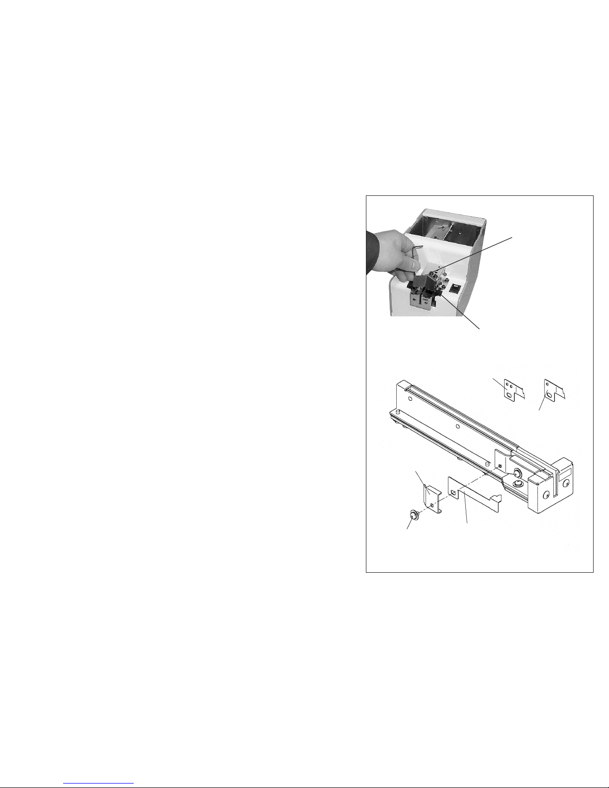
Replacement of the bit guide unit
Replacetheholdingplatewhenthereisdicultyinusingit,such
asafterexcessivewear.
Whenreplacingtheholdingplate,removethebitguidesectiono
thebodytopreventamountingscrewfromfallinginsidethebody.
•Asinthediagramontheright,removethebitguidesectionand
replacetheholdingplate.
•RefertoP.6,“Check/adjustmentoftheholdingplate”for
mountingadjustments.
Replacement of the bit guide assembly
Replacethebitguidewhenthereisdicultyinusingit,suchasafter
excessivewear.
•Asinthediagramontheright,removethemountingscrewsand
replaceit.
•RefertoP.8,“Check/adjustmentofthebitguide”formounting
adjustments.
Removethebitguide.
Fixingscrews,2pieces
Removethebitguide.
Fixingscrews,2pieces
-15-
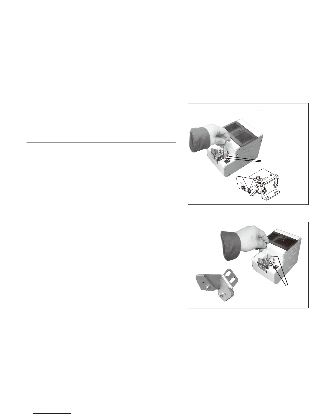
◆ Replacement of the stopper
Replacethestopperwhenthereisdicultyinusingit,suchasafter
excessivewear.
•Asinthediagramontheright,loosentherailxingscrewsandpull
outtherailfromthebody.
•Thestoppercanbechangedasinthediagramontheright.
•Therearethreetypesofstoppers.
•Becarefultocorrectlymatchthenewstoppertothenominal
diameterbeingused.Determinethetypeofstopperbyexamining
theholeofthemountingsection.
Railxingscrew
Pullouttherailtowardyou.
Thisshapeis
for∅ 1.0.
Thisshapeisfor
∅ 1.2and∅ 1.4.
Stopperxingplate
Stopper
(Thisshapeisfor∅1.7-∅ 3.0.)
Fixingscrew
M2.6 × 4
-16-
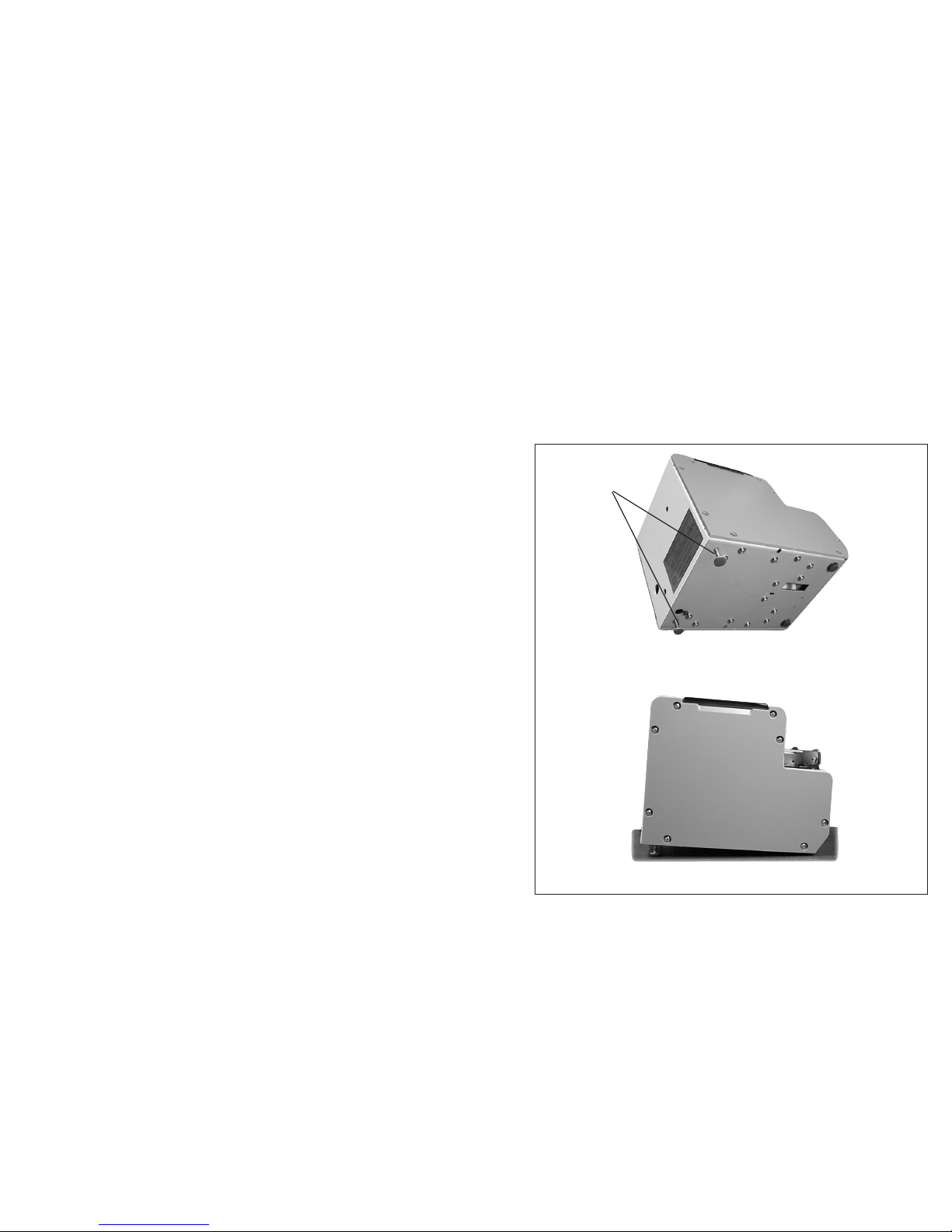
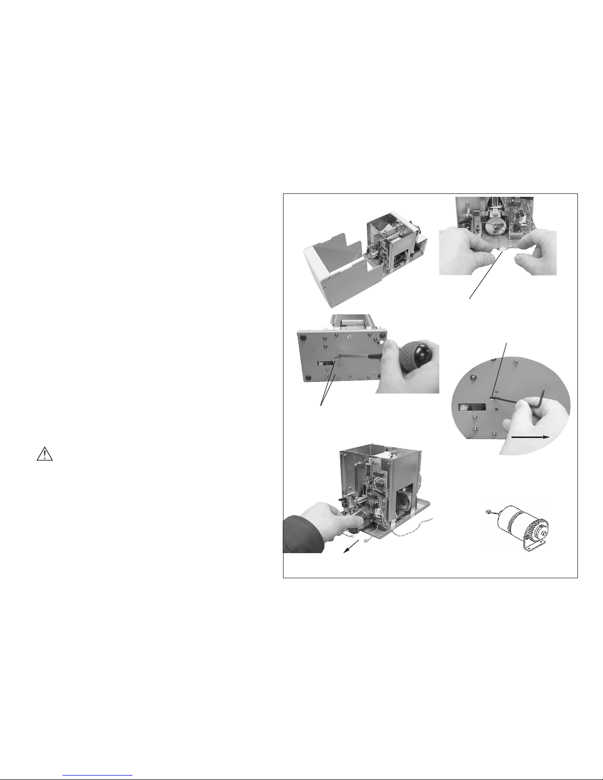
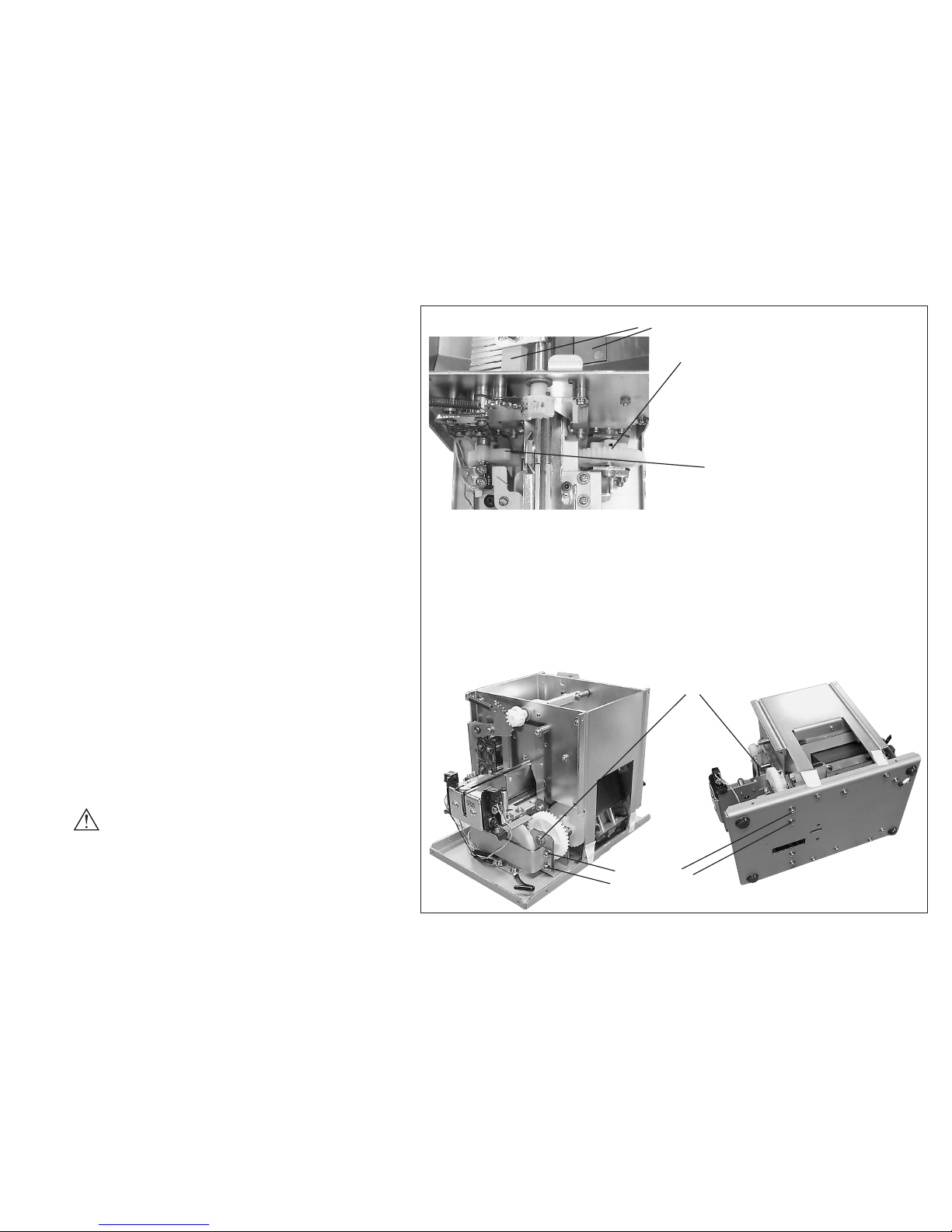
Replacement of the main motor unit
Replacethemotorafteritisdamaged.
•Removethecoverfromthebody.(Duringremoval,
asinthediagramontheright,thecovermounting
screwsshouldberemovedtogetherwiththefront
cover,leavingthefourscrewsoftherearinplace.)
•Removethemotortrunkconnector.
•Removethemotormountingscrewsonthemotor’s
bottomface.
•Pulloutthemotorsectionfromtherearofthebody.
(Tofacilitateremoval,insertahexagonalwrench
orthelikeintothelongholeofthebodybaseand
pushthemotormountingbracketbackward.)
•Becarefulnottobreakmotorwiresbyusingoverly
excessiveforce.
Caution:UnplugtheACadapterfromthewalloutlet
beforedisassemblyofthemotorsection.
Removethecover.
Removethemotortrunkconnector.
Removethemotormounting
screws(M2.6 × 82pieces)
Pushthemotormounting
braketbackwrd.
Thelonghole
Pulloutthemotorsection
fromtherearofthebody.
Mainmotorunit
-17-
Movement timing when replacing a motor
•
Totimeamovementofthe[scoopingblock]
andthatofabrush,thegearsmustbeinmesh.
• Ifonlythemotorsectionisremovedfrom
thebody,themovementscanbetimedby
reassemblingthemotorsectionaccordingto
thetiminginthediagramontheright.
• Ifitisdiculttomeshthedrivinggearofthe
motorsectionwiththerightandlefttrailing
gears.Assemblycanbemadeeasierby
looseningthe mountingoftherightdriving
shaftbracket(seethediagramontheright).
Besuretorefastentheloosenedscrewsafter
mountingthemotorsection.
• Aftermounting,startthemotorandcheck
themovementtiming.(Therightandleft
[scoopingblocks]mustmoveupanddown
almostsimultaneously.)
•
Aftercheckingthemovement,refertothe
wiringdiagramandproperlypositionthe
wiring.(Avoidwiresbeingcaughtwhen
mountingthecoverandbecarefulnottobreak
motorwiresbyusingoverlyexcessiveforce.)
Caution:UnplugtheACadapterfromthe
walloutletbeforedisassemblyofthe
motorsection.
•
Assemblethemotorwhen[scoopingblock]isontherightandleftasmuchaspossible.
• Inordertomaketheheightof[scoopingblock]isontherightandleftjustabout
thesame,thedrivinggearattachedtothemotoraxisandthesub-drivinggearon
therightandleftmustbeinmesh.Then,tightenthescrews(M2.6×8,2pieces)for
themotorbracket.
When the gears do not t:
Loosenthefollowingscrewsandfreethedrivingshaftbracket,anditmakesthe
geareasiertobeinmesh.
Drivingshaftbracket
Attachingscrews
in4places
Drop[scoopingblock]ontherightandleftasmuchaspossible.
Thepinisapproximatwlyvertical.
Thepinisapproximatwly
inclned46degrees.

-18-
7) TROUBLESHOOTING
Caution:Forsafety,alwaysunplugtheACadapterfromthewalloutletbeforemakinganyadjustments.
Trouble Cause Corrective measures
7-1
Themachine
doesnotoperate
thoughthepower
switchisturned
ON.
• Powerisnotsupplied.
• Themachinehasnotunloadedscrewsfromthe
pickupsiteforacertainamountoftime.
• Toomanyscrewswereloadedintothescooping
chamber.
• Aforeignobject(forexample:ascrew)intruded
intothemainbody.
• TheACadapterisfaulty.
• Checktheconnectionofthepowersupplyof
theACpoweradapter.
• Takeoutthescrewfromthepickupsite.
• Adjustthetimersettingknob.
• Reducethequantityofscrewsinthescooping
chambertoaproperloadlevel.
• Removetheforeignobject.
• Consultourservicesection.
This manual suits for next models
7
Table of contents
Popular Sander manuals by other brands


Black & Decker
Black & Decker KA75 user manual

Alpha Professional Tools
Alpha Professional Tools AIR-680 instruction manual

Steel City
Steel City TITANIUM Series owner's manual

FESTA
FESTA 28040 Manual for use

Silver Eagle
Silver Eagle SE730 operating instructions

Bosch
Bosch GWS 22-180 H Professional Original instructions