Hipac 120120 User manual

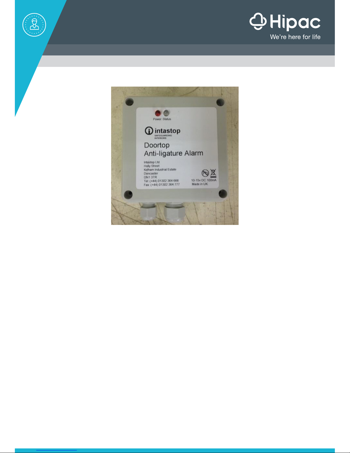
Door Top Alarm
Manual
Contents
1. Introduction
2. Components
3. Architrave detailing (single swing doors)
4. Premanufacturing Information - MUST RETURN TO HIPAC
5. Preparing the Door/Frame
6. Sign off Sheet - MUST RETURN TO HIPAC
7. Wiring Stages Connections
8. Testing/Checks
9. Changing of the Alarm delay time
10. Fail safe
11. Failsafe Alarm sounding
12. Operating Instructions
13. Trouble Shooting
14. Contact Details
15. HFM Electrical Transfer Hinge

1. Introduction
Hipac Door Top Alarms are available in 44m and 54mm thicknesses and to a width to suit the
door (made to measure). The solution is available for Non Fire and FD30 fire door application.
All components are quality checked, tested and signed off before dispatch. The importance
of correct installation, handling with care and connecting in the correct sequence cannot be
emphasised too strongly.
2. Components

3. Frame Architrave Detailing - Single Swing Doors
For reduced ligature when the Door Top Alarm is used on single swing doors (with
SECURAHinge), please note the below architrave detailing / modification is required to allow
for the Domed Cap on top of the hinge.
If new door-set, it is recommended this is planned in at design stage.
Domed Cap Modified Frame Architrave Detail
Domed Cap New Frame Architrave Detail

Door Top Alarm
Ordering Form
Project:
Company:
Checked By:
Duress System:
Date:
Signed:
Door Reference#
Door Width (mm)
Door Thickness (mm)
Hinge Type
Single
Action
Double
Action
Hinge
Fitment
Face Fixed
Single
Rebate
Double
Rebate
Door Type
Single Door
Double
Door
Fire Rating
Yes
No
Condition
New Door
Existing
Door
Door
Handing
(Refer
Diagram)
Figure 1
or 3
Figure 2
or 4
Please use this
diagram to determine
4. Pre Manufacturing Information (Multiple Doors)
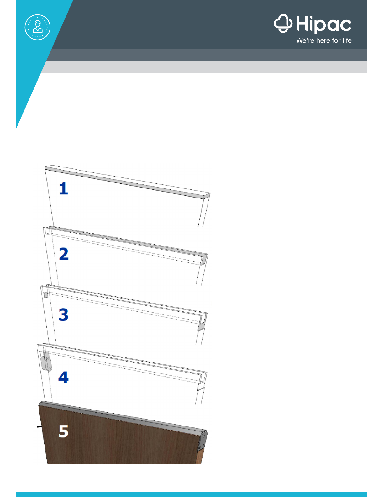
5. Preparing the door
Hipac Healthcare Pty Ltd can take no responsibility for incorrect operation of Door Top Alarms
that are not fitted as per directed in these instructions.
If retrofitting, then removal of the door is recommended.
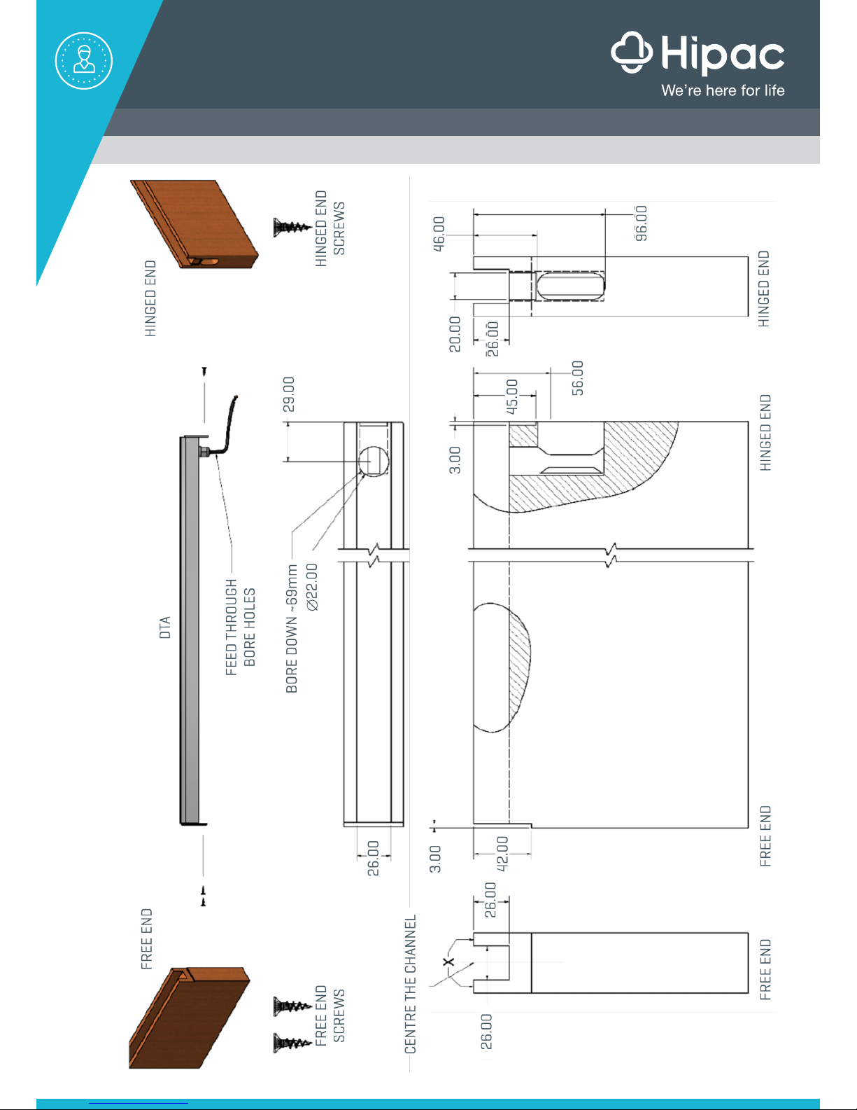
Remove 12mm from the
top of the door
Bore down 69mm from above at 29mm
from the hinged end.
Meet this bore with another from the hinged
side.
This is a channel for routing the cables.
Make channel down centerline on
the top of the door:
• 26x26mm (Not Fire Rated)
• 28x28mm (FD30)
Feed cable and place DTA.
Screw in with fixings provided.
Wire Door top alarm and test.
Recess 3mm:
• HINGED END: From bottom of
channel 18mm and 25mm wide
• FREE END: From bottom of
channel 18mm and full width
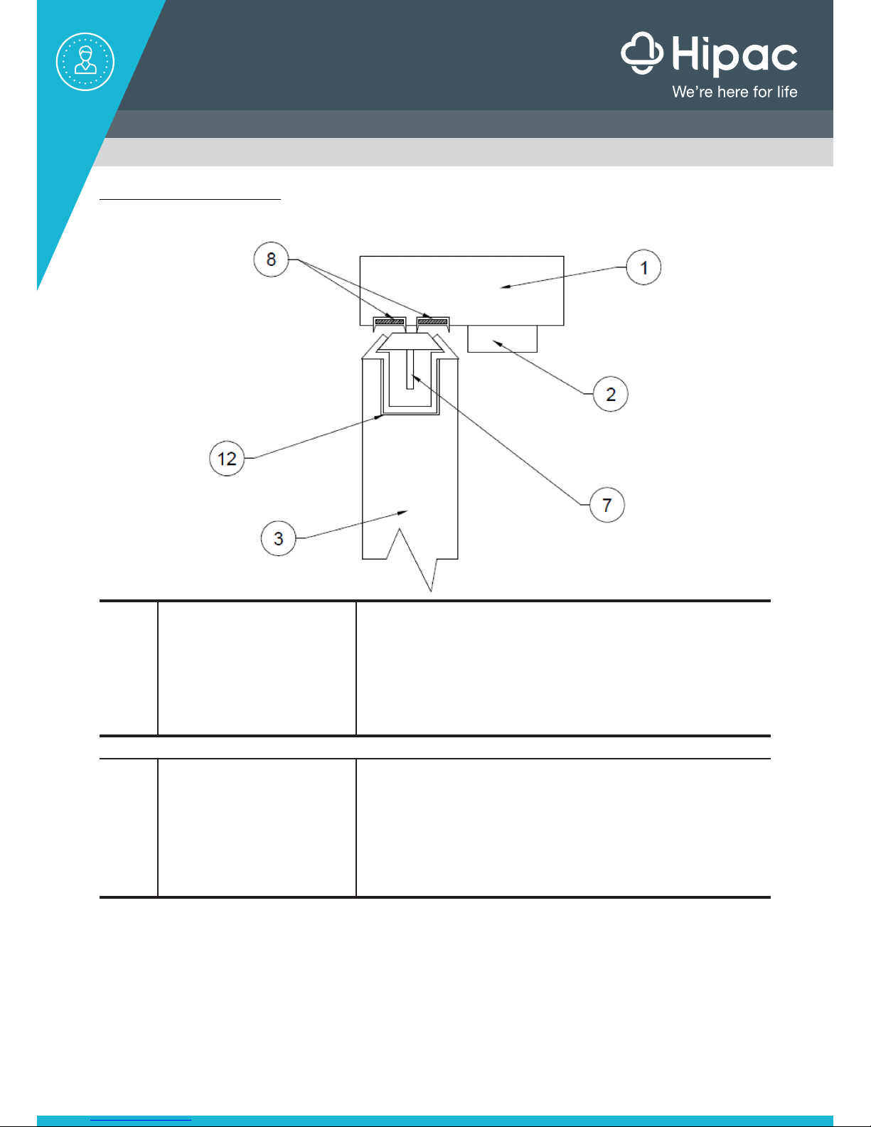
FD30 Applications
Please note for the FD30 applications, the below door-set layout must be applied
8Frame intumescent 1
Supplier:
Reference:
Description:
Lorient Polyproducts Limited
LP1504DS Type 617
2NO. PVC encased sodium silicate based intumescent
strips incorporating elastometric fins, set 6 and 26 from the
exposed edge of frame head. 15 x 4
12 Alarm bar intumescent
Supplier:
Reference:
Description:
Overall size (t):
Intumescent Seals**
Therm-A-Strip**
A white phosphate-based intumescent compound with self-
adhesive tape on one side lining the walls and the bottom of
the alarm bar rebate in the head of the leaf.
1**
6. Door Top Alarm Wiring Test Sign Off Sheet
Overleaf is the completion sign off sheet for each stage of the installation. A completed
signed copy of the above must be returned to Hipac for their records. Failure to return will
invalidate the warranty.
NOTE - To be used in conjunction with the loaned Tested Box.
NOTE 2 - Sheet(s) to be controlled by Project Manager.

Project:
Sales Order Number:
Room
No.
Door Top Alarm
(Connect Alarm to
the hinge)
Electrically Modified
Hinge (Connect the
control cable to the
hinge)
DTA Wired into
Electronics Box
(to match the
connections in the
O&M manual)
Mains power Staff Attack
Interface Unit Magnet test on Door
Name Date Name Date Name Date Name Date Name Date Name Date
7. Wiring Stages / Connections
1) Door Top Alarm
2) Electrically Modified Hinge
3) Cable fed into the ceiling
4) Electronics Box (by others - electrician or staff attack co.)
5) Mains Power (by others - electrician or staff attack co.)
6) Staff Attach Interface Unit (by others - staff attack co.)
7) Staff Attack mains computer / nurses station / fobs (by others - staff attack)
NOTE - Each stage must be signed off on the ‘Sign Off Sheet’ before handing over a copy returned to Hipac. A battery
powered tested unit is loaned to the Door Top Alarm installers so they can sign off stages 1-3 before other companies
get involved.
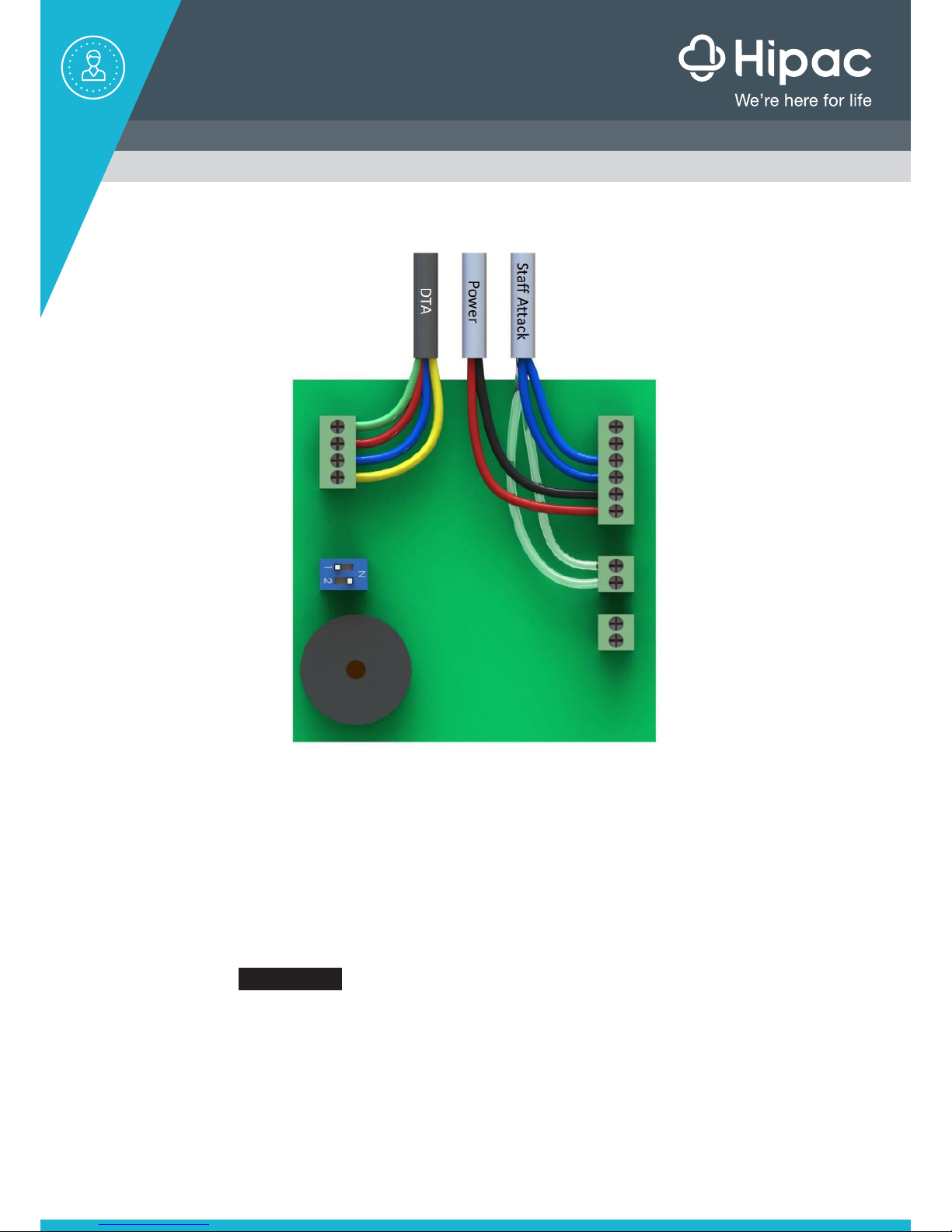
1. Door Top Alarm
The 4 coloured wires from the DTA cable fed into the ceiling, should be connected into the 4
connector block on the left hand side of the electronics boxes as shown.
It is extremely important the wires are connected in the correct junction box:
Green LED = Green Wire
Red LED = Red Wire
Switch = Blue Wire
Switch Common = Yellow Wire
Wiring into the electronics box should be as follows:
Green
Red
Blue
Yellow
Cables codes
Green - Green LED
Red - Red LED
Blue - Trigger switch
Yellow - Common
Staff attack wiring
Wire to normally closed (recommended)
or normally open.
Tamper loop
Tamper loop
Normally closed
Alarm contacts (NC)
PSU - (Black)
PSU + (Red)
Normally open
Alarm contacts (NO)
External sounder PSU-
External sounder open drain
2. Power
The power cable has 2 cables. The black cable is connected to the PSU (-) and the red wire is
connected to the PSU (+). The PSU connectors are located on the right hand side of the box.
The Power can either be from the Staff Attach System (if available)or mains power. If mains
power, it MUST BE transformed down to 12V.DC.
Once power is connected, the red LED on the outside of the box should light up.
If the power is connected without the Door Top Alarm in place, the unit will cycle through the
following sequence - Power LED (red) comes on and the Status LED will cycle green, amber,
and red then extinguish. When the pre-set delay time has elapsed, the LED will turn red and
the internal alarm will sound for approximately 5 seconds. After a total of 20 seconds, the
unit will return to standby mode.
3. Staff attack
The staff attack is connected into EITHER the Normally Closed OR Normally Open
connectors on the right hand side of the box.
Hipac recommend, where possible, the Normally Closed connections are used as this will
allow a notification alarm to sound if there is a power failure or wire breakage. In the Normally
Open connections re used, it may still be possible to obtain a non-audible notification if there
is a failure e.g. messages appears on nurse’s station display unit. Please consult the Staff
Attack supplier.
NOTE - The staff attack should not be connected until the Door Top Alarm and Power stages
have been signed off. (The alarm could go off as the Door Top Alarm has failsafe system built
in).
NOTE 2 - All the wiring should be checked and signed off at each stage on the supplied sign
off sheet during installation by the various contractors. If any problems occur during the
installation stages, Hipac will not attend site to carry out an investigation without proof that
all the stages have been signed (or stages up to when the problem has occurred). If Hipac
attend site and it is proved a stage was signed off in error, this will be chargeable at a day’s
rate.
This manual suits for next models
1
Table of contents
Popular Security System manuals by other brands


EDM
EDM Solution 6+6 Wireless-AE installation manual

Highway Safety Group
Highway Safety Group EA401 user manual

Siren
Siren LED GSM operating manual

Detection Systems
Detection Systems 7090i Installation and programming manual

Se-Kure Controls
Se-Kure Controls MicroMini SK-4841 instructions

Siemens
Siemens FDM273 manual