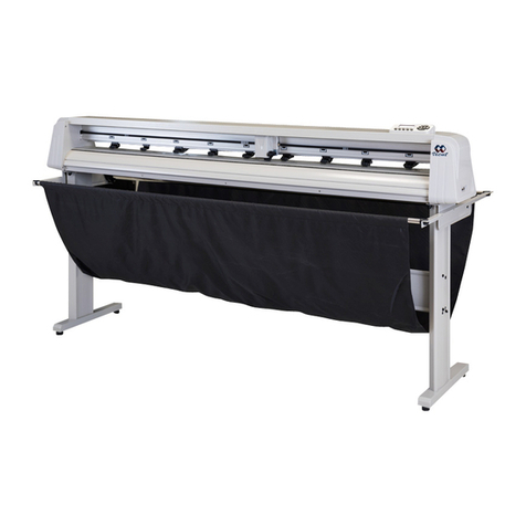
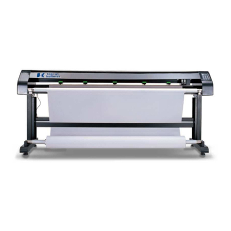
Hipo Technology HH JET Series User manual

Hipo INKJET plotter manual
0
HIPO
JET PLOTTER MANUAL

Hipo INKJET plotter manual
1
Words to Customers
Thank you for purchasing the Hipo plotter. It is our great honor to have
you as our customer. Upon your using of this product, please be sure to
read this manual carefully.
This manual is compiled to provide you with the system configuration,
installation steps, method of operation, and other information to ensure
the correct use of this product.
To timely receive our comprehensive after-sale services, please
contact:
Tel: 0086-10-82380636
Fax: 0086-10-82490122
E-mail: [email protected]
Declare
HipoJET plotter has registered in the Chinese Patent Office and
Trademark Office.
The trademark and trade name used in this manual belong to Beijing
Hipo Technology Co., Ltd and are protected by Chinese laws and
international treaties.

Hipo INKJET plotter manual
2
Contents
Chapter 1 Introduction ........................................................................................................... 3
Chapter 2 Preparation before installation ............................................................................. 4
(1)computer system requirements .................................................................................. 4
(2)Software output formats .............................................................................................. 4
(3)power requirements ..................................................................................................... 4
Chapter 3 Quick installation ................................................................................................... 5
Chapter 4 Installation of USB driver ....................................................................................... 7
Chapter 5 Plotting Center ..................................................................................................... 11
Chapter 6 Plotter Operation Panel ....................................................................................... 26
Chapter 7 Application ........................................................................................................... 27
Chapter 8 Notes.................................................................................................................... 29

Hipo INKJET plotter manual
3
Chapter 1 Introduction
Welcome to our HH JET series plotter. This plotter incorporates world fist-class
technology, generating stable performance, with elegant printing graphics and
comparatively high accuracy. It is very cost-effective and enjoys simplicity of
operation, with advanced automatic paper collecting and discharging functions.
HH JET is favored by the industry, especially for plotting large-breadth
Engineering Line Graphs, Garment Layout Maps, Oil Logging Maps,
Geological Survey Maps, Land Capability Map, and so on.
Our goal is to generate efficient output, save the cost of labor and production,
ultimately enhancing your competitiveness in the industry.
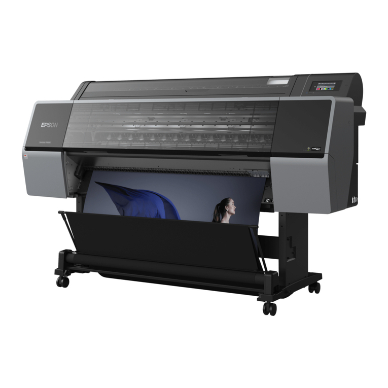
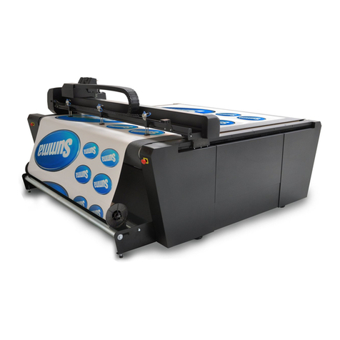
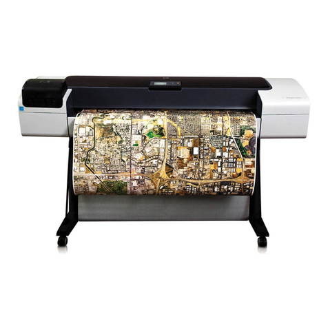
HHJET plotter Front View

Hipo INKJET plotter manual
4
Chapter 2 Preparation before installation
(1)computer system requirements
1、 Microsoft Windows 2000/xp
2、 Processor: Pentium 166M or above
3、 Memory: 512M or above
4、 Hard disk: 1G or above
5、 Driver: 4x or above
6、 USB2.0
(2)Software output formats
The Printout Administrative Center of HHJET only recognizes documents of
the following formats: *.plt、*. hpg、*.hpgl、*.dmpl、*.dxf, thus require
application software capable of generating the above formats, for instance,
AutoCAD and Apparel CAD. Or, you can also transfer documents of these
formats to the plotter.
(3)power requirements
1. Provide AC Power of 220V/50Hz(in some areas 110V/60Hz)in
accordance with the requirements of the plotter,with voltage fluctuation under
10%.
2. Reliable ground wire is a must。
3. Power line should be three-core or above
cables (one of them is groundwire) whether in
American or European Plug Boxes.

Hipo INKJET plotter manual
5
Chapter 3 Quick installation
(1) Installation Diagram
(2) Installation Steps
(a)Dismantle the packing box
1) Check the parts according to the packing list
2) Read the manual carefully
(b) Assemble the foot bars and upright posts according to the
Installation Diagram. The left and right upright posts and foot bars should
be paralleled. Do not screw down the two screws at the top of the left and
right upright posts yet; Screw them a little, not so tight, to assist the
installation of the handpiece.
(c) Add the draw rod according to the diagram. Remember not to
screw so tight of the screws on both ends of the draw rod temporarily, so
as to adjust the parallelism between the posts if needed and assist the
installation of the handpiece.
(d)Add the handpiece. It takes two people to put the handpiece
horizontally on the outer convex bolt of the upright posts, and tighten the
screws. Make sure to tighten the other screws with the precondition that
the left and right upright posts are paralleled.
(e) Add paper-collecting axle.
(f) Add paper-feeding axle and paper scroll.
(g) Add the paper-collecting balance pole and put it on its frame.
(h)Add the Nozzle. Be careful not to damage the touch spot of the
nozzle. Do not crash the nozzle against hard wall of the ink car to avoid
damage on the nozzle. Make sure that the nozzle is properly installed.
See:

Hipo INKJET plotter manual
6
Wrong plugging Correct plugging
(i) Connect the Three-core cable between the handpiece and the
draw rod. Make sure that the plug matches the socket, and screw down
the plug body.
(g) Connect the USB Interface cable.
The computer should be turned off when connecting USB cable. One
end of the cable is connected to the USB port of the computer and the
other to the USB port of the plotter. Make sure to fix it in the clip.
(k) Connect the power cord.
When the power is switched to “O”, connect one end of the power
cord with the plotter, and the other end to the power patch board which
has reliable protective groundwire.
Attention: please make sure that the line voltage is consistent to
the Voltage parameter labeled on the plotter.

Hipo INKJET plotter manual
7
Chapter 4 Installation of USB driver
1. copy to your computer,better under C drive.
2. double click , Interface appears as follows:
3. click ‘INSTALL’ and wait until the end of installation with the following
interface, and click ‘OK’ to finish installation.
4. plug the USB port cable of the plotter,and turn on the power of it,there will
be prompt of finding new hardware,(CH372/CH375) with the following
interface, and the installation automatically starts.

Hipo INKJET plotter manual
8
5. click “next”
6.click‘next, there will be the following installation process:
7. Automatic installation is done, with the following interface:

Hipo INKJET plotter manual
9
8. Finally, there will be a prompt in the desktop tray:
9. If the operating system is Windows2000,there will the following interface
when pressing “reset” on the plotter panel or plucking the USB plug, which is
quite normal. Just click “ok”.
10. Better equip the computer with USB2.0 protocol to ensure fast data
transmission bauds.
11. If the CH372/CH375 drive is successfully installed, plug in the USB port
cable of the plotter, and switch it on. With the following steps you will find
the device, click the right mouse button on “My Computer”.
Select “properties”

Hipo INKJET plotter manual
10
Select ‘device manager’
‘USB CH372/CH375’ is shown under ‘peripheral interface’, indicating
that the drive is connected normally.

Hipo INKJET plotter manual
11
Chapter 5 Plotting Center
(1)software installation
Hpgl2 program is the PC terminal software exclusively used in the ink-jet
plotter produced by HH. Its function includes graphic browsing and plotting,
parameter settings and correction of the plotter. It works under Windows
2000/XP.
Hpgl2 program is a “green” software, and needs no installation. Just copy it
under C drive and set up the appropriate directory, and change the property of
this directory and all the documents within it to “Archive”.
Double click Hpgl2.exe to start the program. See its main interface:
Figure 5-1 The main interface of output center
(2)menu introduction
This section simply goes through the menus of Hpgl2.exe,More detailed
introduction is in “using procedure”.
Files ---
Open: Read and display graphics
Merge: combine several independent documents into one file for printing
Close: close the currently displayed graph
Plot: plot the currently displayed graph
Designated starting point plot: similar to “plot”, but allows plotting from a
designated starting point
Recent Documents: Show recently opened file name and path
Exit: end the program

Hipo INKJET plotter manual
12
View---
Zoom in: to enlarge the graphs zoom by one time at a time
Zoom out: to decrease the graphs zoom by one time at a time
Moderate: to display the panorama of the graphic
Zoom: to set the percentage of the graph display
Tools---
Automatic plotting: to automatically print documents (including newly
added ones) one by one from a Specified directory. A document’s number of
times of printing can be determined in “listed files”.
Automatic plotting directory: to specify the path of automatic plotting files
just once, and it will automatically memorize it.
History: to view the files having been plotted.
Language---
English: to switch the language of the software to English
Simplified Chinese:to switch the language of the software to Simplified
Chinese
Traditional Chinese: to switch the language of the software to Traditional
Chinese
Configuration---
Graphics configuration: to set the parameters of graphics file
Software Configuration: Including the “nozzle-preheating”, “ink-saving
model”, etc
Plotter Configuration: to set the precision, dislocation, docking and other
parameters of the plotter
Help---
Manual: to display this manual
About: Software version, and other information
(3)Shortcut Key Description
The function of the shortcut keys is in accordance with the function of the
menu (including sub-menus). See Figure 5-1 of the main interface of the
output center for more details: if you move the cursor to the shortcut keys,
there will be corresponding text.
(4)using procedure
This section introduces every function of hpgl2, which falls into seven parts:
language settings, Graphics settings, graphic displays, Plotter settings,
graphic plotting, automatic plotting, and plotter correction.
(a), language settings
Click “Language” in the menu, and select the needed language among the
three.

Hipo INKJET plotter manual
13
Figure 5-2 Language Settings
(b), Graphics settings
Click “settings”-“graphics settings”, and the following dialog box will pop out:
Figure 5-3 Graphics Settings
① Determine the size of graphics
The first method is to automatically determine the size of graphics
according to the file content. In this way, it will automatically find the plotting
scope according to plotting instruction.
The second method is to follow the specific size needed by the customer.
Generally, this method is not recommended, because it may result in loss of
effective graphics.
②DXF
If DXF-formatted files are selected, you will have to determine the system
of units based on the actual situation.
③Parallel movement settings
i、automatic parallel move
To automatically overlap the graph origin with the plotter origin
ii、designated parallel move
To designate the graph to parallel-move a certain distance along the
width direction. The numerical value of the designated parallel move is the
absolute distance between the graph origin and the plotter origin (see Figure

Hipo INKJET plotter manual
14
5-5). With this function, it is convenient to choose different plotting origins on
the plotting paper when printing it.
If you close the current graph, the numerical value of the designated
parallel movement will be reserved. So when there’s no need of specifying
starting point of plotting, please choose “automatic parallel move”. If the
parallel move amount is too large, the graph may exceed the printing area,
resulting in incomplete printing. Then the software will give a prompt (see
Figure 5-8); press “ok” to refill the parallel move data.
Figure 5-5 Parallel Move
Figure 5-8 over parallel move prompt
④ Line width settings
The greater the line width value is, the wider the line is and therefore the
clearer graph. But at the same time, it consumes ink faster. Generally, select
the default line width “1” or “2” is fine. If “Ignore the line width setting of the
graph file” is selected, the line width will comply with the "Default Line Width"
when printing. If not, the line width will comply with hpgl2 file formed by CAD
when printing, and has nothing to do with the "Default Line Width". But if the
hpgl2 file does not specify line width, it will still comply with the "Default Line
Width".
(5) Graphic displays
Click “file”-“open”, there will be a dialog box to select a graphic file, and a
mini-marker will be displayed at the bottom. As soon as the path and type of
the file is selected, the next time you click “open” will directly point to this path.

Hipo INKJET plotter manual
15
Figure 5-9 Open file lists
(6) Merging of files
It’s a waste of time and paper to print single files. Thus this function helps
to combine several single files into one for printing.
Click “file”-“merge”, and there will be a dialog box of file path, press “ctrl” to
select files that needs to merge, and then click “open”.
(7) Plotter configurations
Click “configuration”-“plotter configurations”, (see Figure 5-10), including
basic configurations, correction settings, and nozzles settings.

Hipo INKJET plotter manual
16
Figure 5-10 Plotter Configurations
①、basic configurations
⑴ select the Graphics Resolution of 300dpi or 600dpi
⑵ the plotter width is the biggest efficient output width of the plotter, varying
with different types of plotter, generally between 1600-2200mm.
⑶ the plotting speed means the speed of the nozzle group to move from left to
right, or right to left. Options are “slow” or “fast”.
⑷ the paper rolling speed means the speed the plotter moves forward every
time it finishes a line. Options are “slow” or “fast”.

Hipo INKJET plotter manual
17
② nozzle settings
Click ‘√’ of “nozzle settings” (see figure 7-6), and you can change
corresponding parameters.
For two cartridges plotter, you need click ‘√’ for only A and B as following:
For four cartridges plotter, you need Click ‘√’ for A, B, C and D.

Hipo INKJET plotter manual
18
Figure 7-6 nozzle settings
A, B, C, D represents the actual location of the corresponding nozzles,
options are A, B, C, D (Single-nozzle mode); A+B、B+C、C+D (Double nozzle
mode); A+B+C、B+C+D (Three-nozzle mode); A+B+C+D (Four-nozzle mode);
altogether ten modes.
Output testing patterns employs Nozzle D as the standard. Through
adjusting the figures in the corresponding column in the boxes below, you can
make the lines plotted by Nozzle A, B, C to align with that by Nozzle D. If the
lines of the certain nozzle need to be moved left, you need to diminish the
figure in the corresponding column, vise versa. (See Figure 7-7, the figures of
nozzle A, B need to be diminished, while the figure of nozzle C needs to be
increased. The figure varies between 150 and 165)
Figure 7-7 nozzle displacement
In a similar way, nozzle D is the standard. You can adjust the figures in the
corresponding column below nozzle A, B, C to make the lines plotted by nozzle
A, B, C. D not to overlap or separate. Diminish the figure if you want the lines
to overlap, or increase the figure to separate the lines. (See Figure 7-9, the
figures of nozzle A, C should be diminished while the figure of nozzle B needs
to be increased. The figure varies between 71 and 76.)

Hipo INKJET plotter manual
19
Figure 7-9 the overlapping or separation of nozzles
③ Correction of displacement
If in the process of plotting, there’s the situation of Figure 7-12, you need to
fill in a positive number in the column of correction (See Figure 7-10); The unit
of the figure is mm, accurate to 0.01mm. The figure is normally below 2.5mm.
Repeatedly adjust the number will generate the best effect.
Figure 7-10 correction of displacement
Figure 7-12 fill in a positive number in the column
If in the process of plotting, there’s the situation of Figure 7-13, you need to
fill in a negative number in the column of correction (See Figure 7-10). The unit
of the figure is mm, accurate to 0.01mm. The figure is normally below 2.5mm.
Repeatedly adjust the number will generate the best effect.
Table of contents
