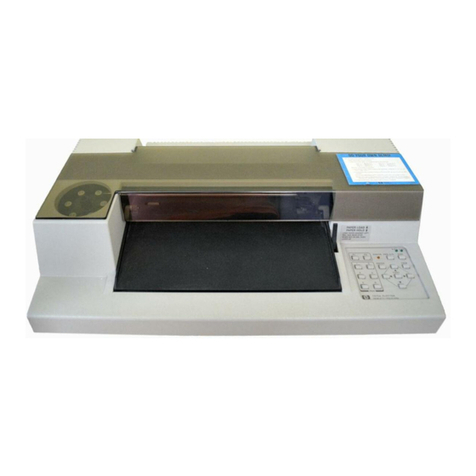
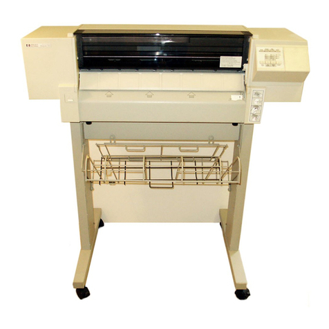
HP 7475a User manual

-------------(h!J
~:~KL.f~6--------------.
SERVICE MANUAL
HP
7475A
GRAPHICS
PLOTTER
SERIAL NUMBERS
This manual applies
directly
to
plotters
with serial numbers prefixed
2541
V.
For additional important information about
serial numbers,
see
PLOTTERS COVERED
BY
MANUAL
in Section
I.
©1983, 1987 by HEWLETT-PACKARD1COMPANY
16399
W.
BERNARDO DRIVE, SAN DIEGO,
CA~IFORNIA
92127-1899
MANUAL
PART NO. 07475-90000 Printed:
AUGUST
1987

Model 7475A Table ofContents
TABLE
OF
CONTENTS
Section
I
GENERAL
INFORMATION
. . . . . . . . . . . . .
1-1
1-1.
Introduction
. . . . . . . . . . . . . . . . . . . . . . .
1-1
1-6.
Specifications . . . . . . . . . . . . . . . . . . . . .
1-1
1-8.
Safety ConsidE!rations . . . . . . . . . . . . .
1-1
1-10.
Plotters Covered
by
Manual
. . . . . . . .
1-1
1-15. Description . . . . . . . . . . . . . . . . . . . . . . . .
1-2
1-19. Line Voltage
and
Fuse
Selection....
1-2
1-23.
Grounding
Requirements . . . . . . . . . .
1-3
1-25. Options . . . . . . . . . . . . . . . . . . . . . . . . . . .
1-3
1-29. Accessories Supplied . . . . . . . . . . . . . . .
1-6
1-31.
Recommended
Test
Equipment
. . . . .
1-6
1-33.
Packaging
for
Shipment
. . . . . . . . . . .
1-6
II
OPERATING
AND PERFORMANCE
TEST
. . . . . . . . . . . . . . . . . . . . . . . . . . . . . . . . . .
2-1
2-1.
Introduction
. . . . . . . . . . . . . . . . . . . . . . .
2-1
2-3.
Rear
Panel
Switches
(Option
001)
. . . . . . . . . . . . . . . . . . . . .
2-1
2-9.
Rear
Panel
Switches
(Option 002) . . . . . . . . . . . . . . . . . . . . .
2-1
2-13.
Basic
Operating
Test
. . . . . . . . . . . . . .
2-1
2-15. Hewlett-Packard
Graphics
Language
. . . . . . . . . . . . . . . . . . . . . . .
2-2
2-17.
Demonstration
Plot
. . . . . . . . . . . . . . . .
2-2
2-19.
Test
Program
. . . . . . . . . . . . . . . . . . . . . .
2-2
2-21.
Repeatability .
....
. . . . . . . . . . . . . .
..
.
2-2
III
ADJUSTMENTS.........................
3-1
3-1.
Introduction
. . . . . . . . . . . . . . . . . . . . . . .
3-1
IV
REPLACEABLE PARTS . . .
..
. . . . . . .
..
. . .
4-1
4-1.
Introduction
. . . . . . . . . . . . . . . . . . . . . . .
4-1
4-3.
Exchange
Assemblies . . . . . . . . . . . . . .
4-1
4-5.
Replaceable
Parts
Lists
. . . . . . . . . . . .
4-1
4-7.
Ordering
Information
. . . . . . . . . . . . . .
4-1
4-9.
Code
List
of
Manufacturers
. . . . . . . .
4-1
4-11.
Designations
and
Abbreviations . . .
4-1
V PRODUCT HISTORY
..
. . . . . . . . .
..
. .
....
.
5-1
5-1.
Introduction
.
~.....................
5-1
5-3.
History
of
Assemblies
by
Serial
Prefix
Number
. . . . . . . . . . . .
5-1
5-
7.
History
of
Printed
Circuit
Assemblies . . . . . . . . . . . . . . . . . . . . . .
5-1
Section
VI
SERVICE
. . . . . . . . . . . . . . . . . . . . . . . . . . . . . . . .
6-1
6-1.
Introduction . . . . . . . . . . . . . . . . . . . . . . .
6-1
6-3.
SimplifiedTheory
of
Operation . . . . .
6-1
6-7.
RS-232-C/CCITT V.24
Interface
Circuit (Option
001)
. . . . .. . . .. . . ..
6-1
6-14.
HP-IB Interface (Option 002) . . . . . . .
6-2
6-25.
Microprocessor Circuit . . . . . . . . . . . . .
6-5
6-29.
Read
Only
Memory Circuit . . . . . . . . .
6-5
6-31.
Random
Access Memory Circuit . . . .
6-5
6-33.
Gate
Arrays
A
and
B . . . .
..
.
..
. . . . .
6-5
6-35.
Pen
Carousel . . . .. . .. . . .. . . .. . . . .. .
6-5
6-37.
Motor Servo
Systems
. . . . . . . . . . . . . .
6-5
6-41. Motor Supply
Sensor
Circuit . . . . . . .
6-6
6-44. Motor
Current
Sensor
Circuit . . . . . . .
6-
7
6-46.
Pen
Down Circuit . . . . . . . . . . . . . . . . . .
6-
7
6-48.
Power Supplies
..
. . . . . . . . . .
..
. . . . . .
6-7
6-50. Recommended
Test
Equipment
. . . . .
6-
7
6-52.
Troubleshooting . . . . . . . . . . . . . . . . . . .
6-
7
6-54.
Exchange
Printed
Circuit
Assembly . . . . . . . . . . . . . . . . . . . . . . . .
6-7
6-56.
Drive Motors
and
Pen
Solenoid
....
.
6-
7
6-58.
Troubleshooting Table . . . . . . . . . . . . .
6-8
6-60.
Test
A . . . . . . . . . . . . . . . . . . . . . . . . . . . . .
6-8
6-62.
Test
B . . . . . . . . . . . . . . . . . . . . . . . . . . . . .
6-8
6-64.
Part
Removal
and
Replacement . . . .
6-9
6-65.
Top
Case
Removal . . . . . . . . . . . . . . . . .
6-9
6-66.
Pen
Carousel
Housing
Removal . . . .
6-9
6-67.
Paper
Drive Motor Assembly
Removal
.........................
6-10
6-68.
Pen
Solenoid . . . . . . . . . . . . . . . . . . . . . .
6-11
6-69.
Pen
Drive Motor
and
Belt . . . . . . . . . .
6-11
6-72.
Pen
Carriage, Penholder,
and
Damper
Removal . . . . . . . . . . . . . . . . 6-13
6-
75.
Pinch
Rollers Removal
and
Replacement . . . . . . . . . . . . . . . . . . . . . 6-14
6-76.
Printed
CircuitAssembly
Removal . . . . . . . . . . . . . . . . . . . . . . . . . 6-14
6-77.
Pinch
Roller
Mechanism
Removal . .
6-15
6-79.
Paper
Drive
Shaft
and
Coupler
Removal . . . . . . . . . . . . . . . . . . . . . . . . . 6-15
6-80. Power Module
and
Transformer
. . . .
6-16
6-81. Power Module Wiring . . . .
........
. . 6-16
6-83.
Cleaning
. .
..
. . . . . . . . . . . .
....
. . . . . . 6-16
6-85.
Pen
Stall
Cleaning
. . . . . . .
..
. . . . . . . . 6-17
6-87.
Diagrams
. . . . . . . . . . . . . . . . . . . . . . . . . 6-17
TABLES
Table
1-1.
Specifications
........................
.
1-2.
Line Voltage Selection
................
.
1-3.
Line
Fuses
............................
.
1-4.
Accessories Supplied
..................
.
1-5.
Recommended
Test
Equipment
........
.
2-1.
Baud
Rate
Selection
..................
.
2-2.
7475A
HP-GL
Instruction
Set
.........
.
1-1
1-3
1-3
1-6
1-6
2-1
2-3
Table
4-1.
Parts
List,
Main
PCA, RS-232-C,
Option
001 . . . . . . . . . . . . . . . . . . . . . . . . . . .
4-2
4-2.
Parts
List,
Main
PCA, HP-IB
Option 002 . . . . . . . . . . . . . . . . . . . . . . . . . . .
4-5
4-3.
Parts
List, Mechanical
Parts
. . . . . . . . . . .
4-8
4-4.
Parts
List,
Pen
Carousel
Parts
. . . . . . . . .
4-10
4-5.
Code
List
of
Manufacturers
. . . . . . . . . . . .
4-11
i
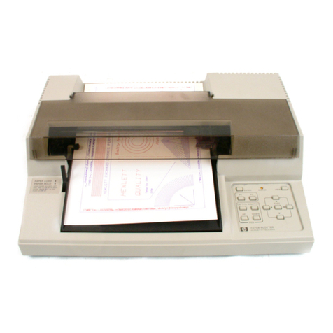
Table ofContents Model 7475A
TABLES (Continued)
Table
Page
Table
Page
4-6.
Reference Designations
and
5-3.
Date Codes ............................
5-1
Abbreviations o 0 0 0 0 I 0 0 0 0 o o o
oo
o o o o o o o o
4-12
6-1.
RS-232-C/CCITT V.24 Interface
Signal
5-1.
Assemblies
by
Plotter Serial Number Levels ···················............
6-2
Prefix ................................
5-1
6-2.
Recommended
Test
Equipment
.........
6-7
5-2.
Item Description .......................
5-1
6-3.
Troubleshooting ··············.........
6-8
ILLUSTRATIONS
1-1.
Model 7475A . . .. .. . . .. . .. . .. . .. .. . .. . . .
1-0
1-2.
Top Case Removal .
..
. . . ... . .. . .. . . .. . .
1-3
1-3.
Line Voltage Selection . . .. .. . . .. . .. . . ..
1-4
1-4.
Power Cord Configurations . .. .. . . .. . ..
1-5
2-1.
Pl
and
P2 Button
and
Power Switch
Locations . . .. .. .. . . .. . . .. . .. .. . . . .. ..
2-3
2-2.
Demonstration
Plot
. . .. .. . .. . .. . . .. . .. .
2-5
2-3.
Test
Program
. . . .. .. . . .. . .. . .. . .. .. . .. .
2-6
2-4.
Features
Test
Plot
. . .. .. . . .. . . .. . .. . . ..
2-9
2-5.
Repeatability
Test
Points . .. .. . . .. . .. . .
2-10
4-1.
Model 7475A Exploded View . . .. .. . .. . .
4-9
4-2.
Pen
Carousel
Parts
. . .. .. . . .. . . .. . .. . ..
4-10
6-1.
7475A Simplified Block Diagram . . .. .. .
6-1
6-2.
RS-232-C/CCITT V.24 Interface
Circuits . . .. .. .. . . .. . .. . . .. .. .. . . .. . .
6-3
6.-3.
HP-IB Interface Circuits
and
Handshake
Timing
Diagram
. . .. .. . . .. . .. . .. . .. ..
6-4
6-4.
Quadrature
Waveforms . . ... . .. . .. . . .. .
6-6
6-5.
Motor Servo System Block
Diagram . . . . . ... . . .. . .. . .. . . ... . . .
6-6
6-6.
Drive Signal · .ses . . .. .. . .. . . .. . .. . . ..
6-9
6-7.
Top Case Ret._Jval . . .. .. . . .. . . .. . .. . . ..
6-9
6-8.
Pen
Carousel Cable . . ... . . .. . .. . .. . .. . .
6-9
11
6-9.
Pen
Carousel Housing . . . ... . . . .. . . .. . .
6-10
6-10.
Paper
Drive Motor
and
Solenoid
Cables . . .. .. . .. .. . . .. . . .. .. . . .. . . . .. .
6-10
6-11.
Paper
Drive Motor Clamp
and
Pen
Drop
Shield . . . ... . .. . .. . . .. . . .. .. . . . .. . . ..
6-10
6-12.
Paper
Drive Coupler
Parts
. . .. .. . . . .. . .
6-11
6-13.
Pen
Solenoid
and
Pen
Drive . . . . .. .. . . ..
6-12
6-14.
Pen
Drive Tensioner . . . .. .. . . .. . . .. . . ..
6-12
6-15.
Pen
Carriage
. . . .. .. . . .. . . .. . .. . . . .. .. .
6-12
6-16.
Measuring Pen Down Force . . . .. .. . . .. .
6-14
6-17.
Pinch
Rollers . .. . .. . .. . . .. . . .. . . .. .. . . .
6-14
6-18.
Chassis Assembly Removal . . . . .. .. . . ..
6-14
6-19.
Underside ofChassis Assembly . . . . .. . .
6-15
6-20.
Power Module Removal . . .. .. . . .. . . . .. .
6-16
6-21.
Power Module Wiring . . . .. .. . .. . . .. . . . .
6-17
6-22.
Schematic Diagram Notes . . .. .. . . .. . . .
6-18
6-23.
ANSI Y32.14 Logic Symbols . . .. .. . . . ..
6-20
6-24.
RS-232-C, Option
001
Schematic
Diagram . . ... . .. . . .. . . .. . . .. .. . . .. . .
6-27
6-25.
HP-IB, Option 002 Schematic
Diagram . . ... . .. . . .. . . .. . . .. .. . . . .. .
6-29
6-26.
Power Supply, Schematic
Diagram
.....................
, . . .. . .
6-31

Model 7475A Safety Symbols
General Definitions
of
Safety Symbols
Used
On Equipment
7
OR@
rh
OR
J.
WARNING
I
1-A-26-1
International caution symbol (refer
to
manual):
the
product
will
be
marked with this symbol when
it
is
necessary for
the
user
to
refer
to
the
instruction manual in order to
protect
against damage
to
the
instrument.
Indicates dangerous voltage (terminals fed from
the
interior
by
voltage exceeding
1000
volts must
be
so marked).
Protective conductor terminal.
For
protection against electrical
shock in case
of
a fault. Used with field wiring terminals
to
indi-
cate
the
terminal which must be connected
to
ground before
operating equipment.
Low-noise
or
noiseless, clean ground (earth) terminal. Used
for
a
signal common, as well
as
providing protection against electrical
shock in case
of
a fault. A terminal marked with this symbol must
be
connected
to
ground in
the
manner described in
the
installation
(operating) manual, and before operating
the
equipment.
Frame
or
chassis terminal. A connection
to
the
frame (chassis)
of
the
equipment which normally includes all exposed metal struc-
tures.
Alternating
current
Direct current
Alternating
or
direct current
The WARNING sign denotes a hazard.
It
calls
attention
to
a pro-
cedure, practice,
or
the
like, which,
if
not
correctly performed
or
adhered
to,
could result in personal injury.
The CAUTION sign denotes a hazard.
It
calls
attention
to
an op-
erating procedure, practice,
or
the
like, which
if
not
correctly
performed
or
adhered
to,
could result in damage
to
or
destruction
of
part
or
all
of
the
product.
iii

Section I Model 7475A
7475-A-1-1
Figure
1-1.
Model 7475A
1-0

Model 7475A Section I
SECTION I
GENERAL INFORMATION
1-1. INTRODUCTION
1-2.
This
service
manual
contains
information nec-
essary to
test
and
service
the
Hewlett-Packard Model
7475A Plotter. This
manual
is divided into six sections
as
follows:
I GENERAL INFORMATION
II
OPERATINGAND PERFORMANCE TESTS
III
ADJUSTMENTS
IV
REPLACEABLE PARTS
V PRODUCT HISTORY
VI
SERVICE
1-3.
Information for interfacing, operating,
and
pro-
gramming the Model 7475A is contained
in
the following
publications:
HP
Title
Part
Number
Interfacing
and
Programming Manual
07475-90001
Operation
and
Interconnection Manual
07475-90002
Programmer's Reference Card
07475-90004
1-4.
This
General Information section includes a
de-
scription
of
the
plotter,
its
specifications, options avail-
able, accessories supplied,
and
general
installation
instructions.
1-5. SPECIFICATIONS
1-6.
Table
1-1
lists
the
specifications for
the
Model
7475A.
These
specifications include
the
performance
standards
against
which
the
plotter
is
tested.
1-7.
Also
included
in
Table
1-1
are
supplemental
characteristics.
Supplemental
characteristics
are
not
specifications
but
are
typical characteristics included
as
additional information for the user.
1-8. SAFETY CONSIDERATIONS
1-9.
Safety information relevant to
the
service proce-
dure being described is provided
in
the
appropriate sec-
tions
of
this
manual.
The
Model 7475A
and
this
manual
should be reviewed for safety
markings
and
instructions
before service work isbegun.
Table
1-1.
Specifications
PERFORMANCE
SPECIFICATIONS
Repeatability
With the same pen:
0.1
mm
(0.004
in.)
With a different pen:
0.2
mm
(0.008
in.)
SUPPLEMENTAL
CHARACTERISTICS
Maximum
plotting
area
B/A3: 402.2
mm
(15.8
in.)
X
274.8
mm
(10.8
in.) metric
414.2
mm
(16.3
in.)
X 258.0
mm
(10.2
in.) English
A/A4:
274.8
mm
(10.8
in.)
X
192.2
mm
(7.6
in.) metric
258.0
mm
(10.2
in.)
X 198.2
mm
(7.8
in.) English
Pen
velocity
Pen
down: maximum,
38.1
cm/s
(15
in.ls)
programmable, 1 to 38
emfs
in
1
cm/s
increments.
Pen up: 50.8
cm/s
(20
in.ls)
Addressable
step
size
0.025
mm
(0.00098 in.)
Acceleration
Approximately 2g
Power
requirements
Source:
100,
120,
220,
or
240
Vac -10%, +5%
Frequency:
48
to
66
Hz
Consumption:
35
Wmaximum
Size
Length: 57 cm
(22.5
in.)
Width: 37 cm
(14.5
in.)
Height: 13 cm
(5
in.)
Weight
7.2
kg
(15.8
lb)
1-10. PLOTTERS COVERED
BY
MANUAL
1-11.
The plotter serial number
is
located
on
the
rear
panel. Hewlett-Packard uses a two-part serial
number
consisting
of
a four-digit prefix
and
a five-digit suffix
separated
by
a letter
(OOOOAOOOOO).
The
prefix is
the
same
for all identical plotters
and
changes only when a
modification
is
made
that
affects
parts
compatibility.
The suffix is assigned sequentially
and
is different for
1-1

Section I
each
plotter.
This
manual
applies directly
to
plotters
with
the
serial prefix shown on
the
title page.
1-12.
If
the
serial number prefix ofyour plotter is higher
than
the
one shown, one or more update packages of
revised
pages
are
supplied
with
the
manual.
Use
these
new
pages
to
replace
the
original pages.
If
two
or
more
update
packages
are
supplied,
insert
them
in
order
by
revision letter;
that
is, Revision A first,
then
Revision
B,
etc.
The
title
page
will
then
show
the
latest serial prefix
and
the
manual
will apply directly to plotters with
that
prefix.
1-13.
In
addition to plotterchanges, revised pages
may
correct errors
in
the
manual
or include improved proce-
dures.
1-14.
If
the
plotter
at
hand
has
a lower serial prefix
than
the
one
shown
on
the
title page, information
in
the
Product
History section will
adapt
this
manual
to
that
plotter.
1-15. DESCRIPTION
1-16.
The
Model 7475A accepts digital information to
produce
graphic
plots
on
ISO A3, 297 X 420
mm
(11 X
17
in.)
paper
or ISO A4, 210 X
297
mm
(8-1/2 X
11
in.)
paper
orspecial transparency plastic. Disposable pens are avail-
able
in
various
ink
colors.
1-17.
The
six-pen capability permits several colors to
be used
in
a plot
without
stopping
the
plotter to
change
pens
manually.
Pens
are
automatically capped while
they
are
stored
in
the
pen carousel.
1-18.
Seven different line types
are
provided. Labeling
can
be done
in
nineteen
character
sets plus user-defined
characters. Text(labeling)
can
bewritten
in
any
direction,
upright,
or
slanted.
Character
size
is
also variable.
In
addition,
arc
and
circle generation
as
well
as
area
fill
with
various fill types
are
provided.
1-19. LINE VOLTAGE AND FUSE SELECTION
To
prevent
damage
to
the
plotter,
make
sure
the
line voltage
and
fuse selection
is
correct before connectinglinepower.
I
WARN••
I
The
line power cord
and
power outlet
must
have
a protective
earth
(ground)
terminal.
1-20.
The
7475A
primary
powercircuit
can
beconfigured
to operate from
any
one
of
the
following power sources
at
a line frequency
of
48 to 66 Hz, single phase. Maxi-
mum
powerused is 35
W.
1-2
100 Vac-10%,+5%
120 Vac -10%,+5%
220 Vac -10%,+5%
240 Vac -10%,+5%
Model 7475A
1-21.
Line
voltage
selection,
and
the
required
fuse
ratings
for
each
line voltagesetting,
are
specified
on
the
line voltage label which is visible
through
the
small
recessed window
in
the
rear
panel. See Figure
1-2.
Applying a linevoltage of
220
V or240 V
to
the
plotter while
the
linevoltage selec-
tion is
set
for 100 V or 120 V operation
may
damage
the
plotter circuits.
1-22.
The
line voltage selection
may
be changed to con-
form to
the
line voltage
in
a
particular
area.
Use
the
fol-
lowing procedure. I
WARNING
I
The
following procedure should be per-
formed only
by
service-trained person-
nel who
are
aware
of
the
electrical shock
hazards
involved.
a. Set
the
plotter
LINE
switch to
OFF
(O)
and
dis-
connect
the
linecord.
b. Remove
the
plotter top case
by
removing
the
screws indicated
in
Figure
1-2.
Lift
the
rear
of
the
top case
and
the
front will
then
release. When
replacing
the
top case,
make
sure
the
PAPER
HOLD lever extends
through
the
case,
and
that
the
tabs
inside
the
front
of
the
top
case
align
properly above
and
below
the
base
plate.
c.
Line voltage selection is determined
by
the
power
inputconnectionsto
the
transformer
primary
wind-
ings.
Table
1-2
lists
the
wire colors
and
trans-
former contact connections for
each
line voltage.
The
transformer
pin
numbers
are
identified on
the
power module molding. Figure
1-3
illustrates
the
connectionsfor each voltage.
Change
the
wire
connections
as
required
to
conform to
the
desired
line voltage selection.
d. Make sure
the
line fuse is correct according to
Table
1-3.
The
fuseholder
cap
is
the
bayonet
type.
Press
and
turn counterclockwise to remove, clock-
wise to lock.
e.
Change
the
position of
the
line voltage label
block so
that
the
voltage selected
is
right
side up.
This
block
snaps
in
and
out
of
the
power module
molding.
f.
Replace
the
top case,
making
sure
it
fits properly
on
the
front edge of
the
base
and
the
PAPER
HOLD lever extends through
the
case.
g.
Install
the
proper power cord for
the
power
range
selected
and
type
of
mains
outlet to which
the
cord is to be connected.
See
Figure
1-4.

Model 7475A
7475-A-2-1
LINE
VOLTAGE
AND
FUSE RATING
LABEL
REMOVE
THREE
SCREWS
Figure
1-2.
Top Case Removal
LINE
FUSE
1-23. GROUNDING REQUIREMENTS
1-24.
To protect operating personnel,
the
plotter
must
be properly grounded.
The
plotter
is
supplied with a
three-conductor power cable which, when connected to
an
appropriate power outlet, grounds
the
plotter. To
preserve
this
protection feature, do
not
operate
the
plot-
terfrom a power outlet which
has
no grounded connection.
Section I
1-25. OPTIONS
1-26.
The
Model 7475A
is
available with one
of
two
types ofinterface, designated
as
the following options:
Option
001
Option
002
RS-232-C/CCITI'
V.24
Hewlett-Packard Interface Bus
1-27.
Option 016 provides a special "eavesdrop" cable
for Option
001.
1-28.
The
line voltage selection ordered is designated
as
one ofthe following:
OptionOIO
Option012
Option
022
Option024
lOOVac
120Vac
220Vac
240Vac
1-29. ACCESSORIES SUPPLIED
1-30.
The
items listed
in
Table
1-4
are
supplied with
each plotter.
1-31. RECOMMENDED TEST EQUIPMENT
1-32.
Equipmentrequired to
maintain
the
Model 7475A
is listed
in
Table
1-5.
Table
1-2.
LineVoltage Selection
NOMINAL
LINE
VOLTAGE
PINI
IOOV
8
120V
8
220V
8
240V
8
*Wire identification is
by
color code:
8=GRAY
928
=WHITE/RED/GRAY
958=
WHITE/GREEN/GRAY
LINE
VOLTAGE
100/120 v
*220/240V (0.25 X 1.25 in.)
(5X
20
mm)
TRANSFORMERPRIMARY CONNECTIONS*
PIN2 PIN3 PIN4 PIN5
PIN6 PIN7
928
958
8 958 NC 928
NC
928
8
928
958 958
958
NC
958
928 8 928
NC 958 958 928 8 928
Table
1-3.
Line Fuses
FUSE
FUSE
FUSEHOLDER CAP
RATING
HP
PART NUMBER
HP
PART NUMBER
0.6AT
2110-0016
2110-0565
0.3AT
2110-0044
2110-0565
0.315AT
2110-0639
2110-0567
*Either
Part
No. 2110-0044
or
2110-0449
will
provide adequate protection.
Part
No. 2110-0044
is
a
standard
U.S. fuse for
240
V line;
Part
No.
2110-0449
is a
standard
European fuse for
220
V line.
1-3

Section I
1-4
8
928
LINE
VOLTAGE
LABEL
BLOCK
958
8
928
DETAIL
A -
100V
LINE
VOLTAGE
LABEL
BLOCK
8
928
DETAIL
C -
220V
8
928
8
LINE
VOLTAGE
LABEL
BLOCK
928
958
DETAIL
B -
120V
8
958
LINE
VOLTAGE
LABEL
BLOCK
928
8
928
DETAIL
D -
240V
WIRE
IDENTIFICATION
IS
BY
COLOR
CODE:
8
=GRAY
928
=WHITE/RED/GRAY
958
=WHITE/GREEN/GRAY
CAUTION
MAKE
SURE
CORRECT
FUSE IS
INSTALLED.
REFER
TO
TABLE
1-3.
Figure
1-3.
Line Voltage Selection
Model 7475A

Model 7475A
BS
1363A
N
c:::::i
E
D
AS C112
CEE
7-Vll
NEMA
5-15P
NEMA
6-15P
SEV
1011
DHCK-107
HP
Part
Number
8120-1351; 250
V,
13
A,
1
q,
plug
rating.
For
use
in
United
Kingdom, Cyprus, Nigeria,
Zimbabwe,
Singapore.
HP
Part
Number
8120-1369; 250
V,
10
A,
1
q,
plug
rating.
For
use
in
Australia,
New
Zealand.
HP
Part
Number
8120-1689; 250
V,
10/16
A, 1
q,
plug
rating.
For
use
in
East
and
West Europe,
Saudi
Arabia,
Egypt,
South
Africa,
India.
HP
Part
Number
8120-1378; 125
V,
15 A, 1
q,
plug
rating.
For
use
in
Canada,
Japan,
Mexico,Philippines,
Taiwan,
UL
approved
in
United
States.
HP
Part
Number
8120-0698; 250
V,
15
A, 1
q,
plug
rating.
For
use
in
Canada,
UL
approved
in
United
States.
HP
Part
Number
8120-2104; 250
V,
10 A, 1
q,
plug
rating.
For
use
in
Switzerland.
HP
Part
Number
8120-2956;
_250
V,
10
A, 1
q,
plug
rating.
For
use
in
Denmark.
NOTE: All
plugs
are
viewed from
connector
end.
L
=Line
or
Active Conductor(also called
"live"
or
"hot")
N
=Neutral
or Identified Conductor
E
=Earth
or
Safety
Ground
Figure
1-4.
Power Cord Configurations
Section I
Option
No_
900
901
902
903
904
906
912
1-5

Section I
1-33. PACKAGING FOR SHIPMENT
1-34.
If
the plotter is being returned to Hewlett-Packard
for service,
attach
a
tag
indicating
the
type of service
required, model number, full serial number,
and
your
return address. Also include
this
information
in
any
correspondence.
1-35.
If
the
original packaging material
has
been
re-
tained, pack the plotter
in
the same manner
as
it
was
received. The following general instructions should be
used for packing with commercially available materials.
Model 7475A
a.
Wrap
the
plotter
in
heavy
paper
or
plastic.
b.
Use a strongshipping container.
c.
Use a layer of shock-absorbing material
at
least
70
to
100
mm
(3
to 4 in.) thick around all sides of
the plotter to provide
firm
cushioning
and
prevent
movement inside thecontainer.
d.
Seal containersecurely. Mark container FRAGILE
to ensure careful handling.
Table
1-4.
Accessories Supplied
DESCRIPTION
QTY
HP
PART NUMBER
Interfacing
and
Programming Manual 1
07475-90001
Operation
and
Interconnection Manual 1
07475-90002
Programmer's Reference Card 1
07475-90004
*Plotter paper, pad,
8-112
X
11
in. or 1 17800P
210
X
297
mm
(A4),
50-sheets 17802P
*Plotter paper, pad,
11
X
17
in. or 1 17804P
297
X
420
mm
(A3),
50-sheets 17806P
Package of5 fiber-tip pens,
0.3
mm nib width, 1 17847P
1 each blue, green, black, aqua, violet
Package of5 black fiber-tip pens,
0.7
mm
nib width 1 17826P
Package of5 fiber-tip pens,
0.3
mm nib width, 1 17849P
1 each brown, yellow, orange, red, red-violet.
Pen Carousel 1
5061-5080
*Power Cord 1 See Figure
1-4
*Paper size
and
power cord supplied is based on the destination ofthe plotter.
Table
1-5.
Recommended Test Equipment
TYPE RECOMMENDED MODEL
Computer/controller HP
85
Personal Computer with the
appropriateinterface:
HP
82937A HP-IB Parallel Interface
HP
82939A
RS-232-C
Interface
and
HP
8120-3258
RS-232-C
Interface cable
Rom Drawer HP82936A
l/ORom
HP
00085-15003
Digital Multimeter HP3465A
Oscilloscope
HP
1740A
Optical Comparator
B&L
81-34-35
1-6

Model 7475A Section II
SECTION II
OPERATING AND PERFORMANCE TEST
2-1.
INTRODUCTION
2-2.
The
following
information
is provided to determine
whether
the
plotter is
operating
properly.
If
operation
is
not
correct,
refer
to Section VI
of
this
manual
for service
information.
2-3. REAR PANEL SWITCHES (Option 001)
2-4.
A3/
A4.
This
switch
chooses between
Bl
A3 size
paper
and
A/
A4 size paper.
The
switch
is used to
set
the
default
paper
size
only
at
power up.
Subsequent
paper
size
changes
can
be
made
from
the
front
panel.
2-5.
BAUD
RATE. Table
2-1
shows
the
switch
settings
required.
Disregard
any
markings
on
the
switch
itself
and
use
the
1
and
0
markings
on
the
rear
panel
to
determine
baud
rate.
2-6.
PARITY. Two
rear
panel
switches
are
used for
parity
selection.
When
the
SI/PARITY
switch
is
set
to 1
(ON),
the
S2/PARITY
switch
selects odd or even parity.
2-7.
MET/US.
This
switch
is
used
to
program
the
plotting
area
for four
paper
sizes:
Paper
Switch
Maximum
Size
Position
.
Plotting
Area
B/A3
MET
275 x 402
mm
us
10.2 x 16.3 in.
A/A4
MET
192 x 275
mm
us
7.5 x 10.2 in.
2-8.
D/Y.
When
the
EAVESDROP
switch
is
in
the
Y
position, received
data
is
retransmitted
and
the
plotter
does
not
respond
unless
it
is
given
a
"Plotter
On"
instruction.
When
this
switch
is
in
the
D position,
the
plotter responds to all recognized
commands.
2-9. REAR PANEL SWITCHES (Option 002)
2-10.
ADDRESS.
The
plotter's HP-IB
address
is
set
by
five
of
the
seven
switches
on
the
rear
panel.
Disregard
any
markings
on
the
switch
itself
and
use
the
1
and
0
labels
on
the
rear
panel
to
determine
the
address
in
binary
coded decimal.
2-11.
A3/
A4.
This
switch
chooses between
Bl
A3 size
paper
and
A/
A4 size
paper.
The
switch
is
used
to
set
the
default
paper
size
only
at
power up.
Subsequent
paper
size
changes
can
be
made
from
the
front
panel.
2-12.
MET
/US.
This
switch
is
used
to
program
the
plotting
area
for four
paper
sizes:
Paper
Switch
Maximum
Size Position
Plotting
Area
BIA3
MET
275 x 402
mm
us
10.2 X 16.3 in.
A/A4
MET
192 X 275
mm
us
7.5 x 10.2
2-13. BASIC OPERATING TEST
2'14.
The
front
panel
controls
can
be
used
to
test
basic
operation
of
the
plotter; however,
this
procedure does
not
test
the
110 circuits.
a.
Make
sure
six
pens
are
installed
in
pen
carousel.
Table
2-1.
Baud
Rate
Selection
ONE
STOP
BIT
TWO
STOP
BITS
REAR
PANEL
SWITCHES
BAUD
REAR
PANEL
SWITCHES
B4 B3 B2
Bl
RATE
B4 B3 B2
Bl
-- - -
External
0 0 0 0
-- - -
75
0 0 0 1
----110 0 0 1 0
0 0 1 1 150 --- -
0 1 0 0 200 ----
0 1 0 1 300 1 0 1 1
0 1 1 0 600 1 1 0 0
0 1 1 1 1200 1 1 0 1
1 0 0 0 2400 1 1 1 0
1 0 0 1 4800 1 1 1 1
1 0 1 0 9600 --- -
1 =Switch Open; 0 =Switch Closed
2-1

Section II
Before applying power
to
the plotter,
check the line voltage selection (visible
through the small window
in
the rear
panel)
and
make sure the selected line
voltage
and
fuse value are correct.
If
not, refer to Line Voltage and Fuse
Selection
in
Section I.
b. Apply power to the plotter.
c.
With the PAPER LOAD lever
in
the LOAD posi-
tion, place a sheet of paper (ISO
A4/
8-112
X
11
in. or ISO
Aa/
11
X
17
in.)
against
the left-hand
rail
and
the rear guide. Lower the lever to the
PAPER
HOW
position
and
be sure
that
the
plotter is set for the proper paper size.
d.
Select a pen by pressing one of the six pen push-
buttons
and
then operate each of the front-panel
controls. Vertical, horizontal,
and
diagonal lines
(using the directional controls with a pen down)
should
be
smooth.
NOTE
If
the pen is down,
it
will lift when
either
Pl
or P2 is pressed. The VIEW
pushbutton is a latching control. After
VIEW ispressed
once,
the other controls
will not operate until VIEW
is
pressed
a second time. The ERROR lightshould
be on when
in
the VIEW mode. The
ERROR light should be on when the
PAPERlever
is
in
the LOAD position.
If
Pl
or P2
is
pressed while the lever
is
in
LOAD, the ERROR light should
flash. This error may be cleared by
moving the lever to HOLD
and
back
to LOAD,
or
by pressing ENTER
and
VIEW
at
the same time,
in
which case
the plotter initializes again. While the
plotter is ON,
and
the PAPER lever is
in
the HOLD position, the ERROR
lightflashes very briefly approximately
every five seconds when the motor
power supply voltage is sensed.
2-15. HEWLETT-PACKARD GRAPHICS
LANGUAGE
2-16.
The Model
7475A
recognizes the Hewlett-Packard
Graphic Language
(HP-GL)
instructions listed
in
Table
2-2.
2-2
Model 7475A
2-17. DEMONSTRATION PLOT
2-18.
The Model
7475A
contains a demonstration plot
stored
in
Read Only Memory
(ROM).
The running of
this plot will verify proper operation ofmost ofthe logic
circuits
as
well
as
the operation of the paper
and
pen
drive mechanisms; however,
it
does not test the
1/0
circuitry.
To
run
the demonstration plot proceed as
follows:
a. Make sure six pens are installed
in
carousel.
b.
With the PAPER LOAD lever
in
the LOAD posi-
tion, place a sheet ofpaper (A4/ 8-1/2 X
11
in. only)
against
the left
hand
rail
and
the rear guide.
Lower the lever to thepaper
HOW
position.
c.
While holding down buttons
Pl
and
P2, apply
power
to
the plotter.
See
Figure
2-1.
Release buttons
afterinitialization starts.
d.
The resultant plot
is
illustrated in
Figure
2-2.
2-19. TEST PROGRAM
2-20.
The program in Figure
2-3
is
written
in
BASIC
language specifically for the
HP
Model
85
Personal
Computer, but may be adapted to other controllers. This
program tests the input/output circuits
of
the 7475A
and
the majority ofthe logic circuits,
as
well
as
the operation
of the paper
and
pen drive mechanisms. The resultant
plot is illustrated
in
Figure
2-4.
NOTE
Lines beginning with
an
exclamation
point are only explanatory and not
part
ofthe plot program. Those lines may be
omitted when enteringthe program.
The addresses shown
in
lines
130,
and
140
are only examples,
and
may vary
with the system or computer used.
2-21. REPEATABILITY
2-22.
To verify repeatability specification (Table
1-1)
load six new pens
in
the carousel
and
run
the test
program previously described. Using
an
optical com-
parator, verify
that
the repeatability points on the test
plot are within
0.1
mm
using the same pen,
and
within
0.2
mm
using a different pen. See Figure
2-5.

Model 7475A Section
II
POWER SWITCH
7475-A-36-1
Figure
2-1.
Pl
and
P2
Button
and
Power
Switch
Locations
Table
2-2.
7475A HP-GL
Instruction
Set
INSTRUCTION
DEFINITION
VECTOR
GROUP
PA
x,y(,x,y(,-))
Plot
absolute (integer format,
-32
768 to +32 767)
PR
x,y(,x,y(,-))
Plot
relative (integer format,
-32
768
to
+32767)
PU
Pen
up
PD
Pen
down
CHARACTER
GROUP
CAn
Designate
alternate
character
set (n
=integer
from 0 to
4,
6 to
9,
or 30 to 39)
CP
spaces, lines
Character
plot (decimal format,
-128to+127.9999)
CSn
Designate
standard
set
(n
=integer,
0 to
4,
6 to
9,
or
30 to 39
DI
run,
rise Absolute direction (decimal
format
-128to+127.9999)
DR
run,
rise Relative direction (decimal
format-128
to +127.9999)
LB c
....
c Label
ASCII
string
(c
=ASCII
characters)
SA
Select
alternate
character
set
SI
wide,
high
Absolute
character
size (decimal
format
in
centimetres)
SL
tan
angle(+
or-)
Absolute
character
slant
from vertical (decimal format,
tangent
of
angle
from
vertical)
SR
wide,
high
Relative
character
size (decimal format, percentage
of
P2x
-
Plx
and
P2y
-
Ply)
SS
Select
standard
character
set
UC User-defined
character
DIGITIZE
GROUP
DC Digitize
clear
DP
Digitize
point
oc
Output
current
position
and
pen
status
OD
Output
digitized
point
and
pen
status
AXES
GROUP
TL
tp(,tn) Tick
length
(tp
=positive
length,
tn
=negative
length)
XT X-axis tick
YT Y-axis tick
SETUP
GROUP
IP
plx,ply(,p2x,p2y)
Input
Pl
(and
P2) (integer
format
-32
768 to +32 767)
IW xlo,ylo,xhi,yhi
Input
window (integer
format
-32
768 to +32 767)
OP
Output
Pl
and
P2
2-3

Section
II
Model 7475A
Table
2-2.
7475A HP-GL
Instruction
Set
(Continued)
INSTRUCTION
DEFINITION
CONFIGURATION
AND
STATUS
GROUP
DF
Set
default
values
IM
e(,s(,p))
Input
e,
s,
and
p
masks
IN
initialize
OE
Output
error
OS
Output
status
SC
xl,x2,yl,y2
Scale (integer
format
-32
768 to +32 767)
DTc
Define label
terminator
(c
=ASCII
character)
OA
Output
actual
position
and
pen
status
00
Output
options
OF
Output
factors
OI
Output
identification
ow
Output
window
ARC
AND
CIRCLE
GROUP
AA x center, y center
arc
Draw
arc
starting
with
current
position
angle(,chord angle)
AR x center, y center
arc
Draw
arc
with center relative to
current
position
angle(,chord angle)
CI
radius(,chord angle)
Draw
circle
around
current
position
AREA
FILL
GROUP
FT
type
(spacing
(angle)) Fill type
RAx,y
Shade
rectangle, absolute
RRx,y
Shade
rectangle, relative
WG
radius,
start
angle,
Shade
wedge
stop
angle
(,chord angle)
EAx,y
Edge
rectangle, absolut.e
ERx,y
Edge
rectangle, relative
EW
radius,
start
angle,
Edge
wedge
stop
angle
(,chord angle)
PT
thickness
pen
thickness
MISCELLANEOUS
GROUP
ROn
Rotate
axes
in
degrees (n =
0,90)
2-4

GRAPHICS
IMPROVES
COMMUNICATION
SALES
REVENUE
DISTRIBUTION
DIV. -
12%
2000
1500
MANF.
-
38%
DIVIDEND
HISTORY
1000
500
oL-1'~~~.a.-~~_JO.~--"~"'---'
1982 1983
1984
1985
1986
YEARS

Section
II
Model 7475A
10
20
30
40
50
60
70
"Autost"
7475A
FEATURES
PLOT
CJULY
4,1983)
80
90
I
SELECT
ADDRESS
FOR
PLOTTER
INTERFACE
100
CLEAR
110
DI
SP
"ENTER
ADDRESS"
120
DISP
130
DI
SP "
e9.
RS-232-C
140 DISP "
e9.
HP-IB
150
DISP
160INPUT
N
, 1
0'"
'705'"
170
DI
SP "
ADDRESS
I
S"
; N
180
IF
N<99
THEN
GOSUB
1280
190
I
200
I
INIT
7470A &
OUTPUT
P1,P2
&
WINDOW
COORDINATES
210
I
220
OUTPUT
N
USING
11
1,K
11
; "INOP;"
230
ENTER
N ; X1,Y1,X2,Y2
240
OUTPUT
N
USING
11
1,
K
11
;
11
ow;
11
250
ENTER
N ; X3,Y3,X4,Y4
260
I
270
I
DRAW
+
AT
P1
&
P2
&
LABEL
COORDINATES
280
I
290
OUTPUT
N
USING
300
OUTPUT
N
USING
310
OUTPUT
N
USING
320
OUTPUT
N
USING
330
OUTPUT
N
USING
340
GOSUB
1180
II•,
K"
II•,
K"
"I,
K"
"I'
K"
"I'
K"
350
OUTPUT
N
USING
11
1,K"
360
GOSUB
1220
370
OUTPUT
N
LISI
NG
"I,
K"
380
I
390
I
DRAW
&
LABEL
AXIS
400
I
410
OUTPUT
N
USING
11
1,K"
420
FOR
I•1
TO
8
430
OUTPUT
N
USING
11
1,K"
440
NEXT
I
450
FOR
I•1
TO
15
460
OUTPUT
N
USING
11
1,K"
470
NEXT
I
480
OUTPUT
N
USING
11
1,K"
490
GOSUB
1180
500
OUTPUT
N
USING
11
1,K"
510
:iOSUB
1220
520
OUTPUT
N
USING
"1,K"
530
OUTPUT
N
USING
11
1,K
11
540
OUTPUT
N
USING
11
1,K"
550
FOR
I•15
TO
0
STEP
-1
"SP1PA5080,4064PDPUSM+PA";X1;",";Y1
II
CPZ,
- .
3LBP1
=
("
,
VAL$
(x 1),
II
·'
II
,
VAL$
(y 1),
II
)
II
,
CHR
$(3 )
11
PA"
;
x2;
11
, " ;
yz;
11
SM;
"
11
cp - 16' - . 3
LB
p2 = ( '' '
VAL
$(x2 )
·'
11
I
11
,
VAL
$(y2 ) ,
11
)
11
·'
c
HR$
(3 )
II
PA2022' 2464"
11
PA8088,4064"
11
FT4,100,45PA9372,6440RR700,700SP2ER700,700
11
"SP2PA9144, 1016PD
11
II
XTPR-1
011
'0
11
II
PRO,
400YT"
"PUPA2022, 4064"
II
PA8088, 5664"
"FT4,
50,
90PA9722, 5600WG350,
0,
360,
40SP3EW350,,
0,
360,
40"
''SP3PA600,3500DI0,1LBCentimetres",CHRSC3)
"PA700,6966DI"
560
IF
I<10
THEN
OUTPUT
N
USING
11
1,K" ;
"CP1,0"
570
OUTPUT
N
USING
11
1,K" "LB" ,VALSCI ),CHRSC13),CHRSC3),"PRO,
-400"
580
NEXT
I
590
OUTPUT
N
USING
11
1,K"
600
GOSUB
1180
610
OUTPUT
N
USING
"1,K"
620
GOSUB
1220
630
OUTPUT
N
USING
11
1,K"
640
OUTPUT
N
USING
11
1,K"
650
FOR
I•O
TO
8
"PA2022,5664"
"PAZOZZ, 2464"
II
FT1
'o,
OPA9722' 4060PT.
5WG700,
60,
60SP4EW700,
1)0,
60"
II
PA1032, 756SP4"
7475-A-33-1
Figure
2-3.
Test
Program
(Sheet
1
of
3)
2-6

Model 7475A Section II
660
670
680
690
700
710
720
730
740
750
760
770
780
790
800
810
820
830
840
850
860
870
880
890
900
910
920
930
940
950
960
OUTPUT N
USING
"1,K"
NEXT I
II
LB"
' VAL$ (I ) '
CHR
$( 13 ) '
CHR
$( 3 ) '
II
PR
1011 '
0"
OUTPUT N LISI
NG
II
I'
K"
OUTPUT N LISI
NG
II
I'
K"
GOSUB
1180
OUTPUT N LISI
NG
II
I'
K"
GOSUB
1220
"PA4830,516;LBinches",CHRSC3l
II
PA8088'
2464"
II
PA2022'
4064"
OUTPUT N LISI
NG
II
I'
K"
I
"FT1,0,90PA9722,3570PT.5WG700,240,60SP5EW700,240,60"
!
DRAW
CIRCULAR FAN
I
OUTPUT N
USING
11
1,K"
;
"SP4PA5080,4064"
FOR
I•108
TO
508
STEP
100
OUTPUT
705
LISI
NG
II.'
K"
NEXT I
II
CI
II'
I
OUTPUT
705
LISI
NG
II
I'
K"
DEG
"SP6IW3580,2564,6580,5564PA3580,2564ER3000,3000SP5"
FOR
I•O
TO
345
STEP 15
X5•5080+508•COSCI>
Y5•4064+508•SINCil
OUTPUT N LISI
NG
"I,
K"
X5•5080+2200*COSCI)
Y5•4064+2200*SINCI>
OUTPUT N LISI
NG
II
I'
K"
NEXT I
OUTPUT N
USING
11
1,K"
GOSUB
1180
OUTPUT N LISI
NG
II
I'
K"
GOSUB
1220
OUTPUT N LISI
NG
II
I'
K"
970
I
DRAW
LABELS
980
I
"PA"
;VAL$CINTCX5l
>;"
,"
;VAL$CINTCY5)
lj"PD"
II
PA" ; VAL$
(I
NT (X5 ) ) ;
II
'
II
; VAL$
(I
NT (
Y5
) ) ;
II
PU"
I
"IWPA8088,4064;"
II
PA2022'
5664"
"FT4,
50,
90PA9722,
2030WG3so
.•
o,
3SOSP6EW35o, o,
:iso;"
990
OUTPUT N
USING
11
1,K"
;
"SP6PA3810,6514"
1000
OUTPUT N
USING
11
1,K"
"VSSI1,1SL.45LB7475A",CHRSC3>
1010
OUTPUT N LISI
NG
II
I,
K"
II
PA4645,
1778"
1020
OUTPUT N
USING
11
1,K"
"SISLLBFeatures"
,,CHR$C3l
1030
OUTPUT N
USING
11
1,K"
"CP-6,-1L8Plot",CHR$C3l
1040
OUTPUT N
USING
11
1,K"
"PA8088,5664"
1050
GOSUB
1180
1
060
OUTPUT N LISI
NG
II
1,
K"
1070
GOSUB
1220
1
080
OUTPUT N LISI
NG
"11, K"
1090
I
1100
I
FRAME
WINDOW
1110
I
1120
OUTPUT N
USING
11
1,K"
1130
OUTPUT N
USING
11
1,K"
1140
END
1150
I
"PA808B,2464;"
"FT4,100,45PA9372,490RR700,700SP1ER700,700"
"PA5080,4064PDPU"
;X3;"
,"
;Y3
II
EA" ;
X4;
II
'II
;
Y4;
II
SPOPA" ;
X4;
II
'II
;
Y4;
II
;
II
1160
! PEN
TO
PEN
REPEATABILITY
SUBROUTINES
1170
I
1180
OUTPUT N USING
11
1,K"
1190
OUTPUT N USING
11
1,K"
1200
RETURN
1210
I
"PR9,
-9PD247,0,0,
18,
-247,0,0,247,
-10,0,0,
-:~47,"
II
-24
7,
0'
0'
- 1
8'
24
7,
0, 0,
- 24
7'
1
8'
0'0'
247PU"
1220
OUTPUT N
USING
11
1,K"
;
"PR0,512PD0,-1024PU-512,512PD1024,0PU"
1230
I OUTPUT N USING
11
11,K" ;
"-512,0,512,o,o,-512,0,512CI512PU;"
1240
RETURN
1250
I
1260
I
HP
85
RS232C
INTERFACE SETUP
1270
I
1280
CONTROL
10,1
1290
CONTROL
10,2
1300
CONTROL
10,3
7475-A-34-1
16 I RECEIVED DATA GENERATES INTERRUPT
5 I
ACTIVATES
DTR
& CTS
11
I
ACT!
VATES RTS,
DRS
&
DTR
Figure
2-3.
Test Program
(Sheet
2
of
3)
2-7

Section II Model 7475A
1310
1320
1330
1340
1350
1360
1370
1380
1390
1400
1410
CONTROL
CONTROL
CONTROL
10,4
; 3 I 8
BITS/WORD
WITH
NO
PARITY
10,5
; 16 I
ENABLES
HARDWIRE
HANDSHAKE
10,16
; 0 !
NO
CHARACTERS
SENT
AT
EOL
I
I 7470A-OP001
TURN-ON
&
CONFIGURATION
I
OUTPUT
I~
OUTPUT
N
OUTPUT
I~
OUTPUT
N
OUTPUT
I~
USING
USING
USING
USING
USING
"ti'
K"
"ti'
K"
"ti'
K"
II.'
K"
"ti'
K"
II
'c.
("
I
"'c.
J"
I
"'c.K"
I
"'c.Mj j j 13j
10:"
"'c.0;13:"
I
1420
OUTPUT
N
USING
"tt,K" "'c.L"
1430
ENTER
N ; B
1440
DI
SP
"
BUFFER
SI
ZE
I
S"
j B
1450
RETURN
9114
TURN
PLOTTER
ON
LIST1260
ABORT
DEVICE
CONTROL
INSTRUCTION
ABORT
GRAPHIC
INSTRUCTION
TERMINATE
OUTPUT
WITH
Cr
& Lf
SET
HARDWARE
HANDSHAKE
MODE
OUTPUT
BUFFER
SIZE
7475-A-35-1
Figure
2-3.
Test
Program
(Sheet 3
of
3)
2-8

rs:
0
0..
~
P2•(10250,
7796) +
-:i
""'
-:i
Ol
>
i5
i4
7475A
13 + +
12 •
u
~
iO
aq
e;
Cl)
9
('!>
+ +
t.:l
u
~
c..
~
B
'rj
E
('!>
$1)
....
a-
+'
7
;;i
c
u
rn
tJ
--3
6
('!>
rn
....
~
5
0 + +
....
4
3 •
2
Features
Plot
1
0
aim
0 1 2 3 4 5 6 7
+
Pi•
(250, 596)
Inches
r:n
('!>
(")
~-
0
:::s
~
......
c:O
......
Other manuals for 7475a
1
Table of contents
Other HP Plotter manuals

HP
HP DesignJet Z6610 60 User manual

HP
HP CalcPad 200 User manual

HP
HP 7470A User manual

HP
HP DesignJet 700 User manual

HP
HP Designjet 8000s Series User manual

HP
HP DesignJet 700 User manual

HP
HP DesignJet 250C User manual

HP
HP Designjet 330 User manual

HP
HP DesignJet 750c plus Series User manual

HP
HP DesignJet 3500CP User manual

HP
HP 7470A Owner's manual

HP
HP 650c - DesignJet Color Inkjet Printer User manual

HP
HP Designjet 230 User manual

HP
HP 7470A Owner's manual

HP
HP 7475a User manual

HP
HP Designjet 230 User manual

HP
HP 54 Basic Cutter User manual

HP
HP Designjet T1200 series User manual

HP
HP C2858A User manual

HP
HP DesignJet 200 User manual