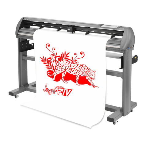
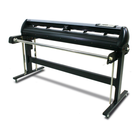
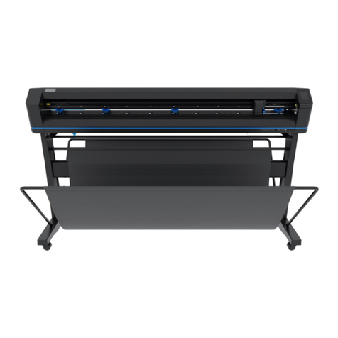
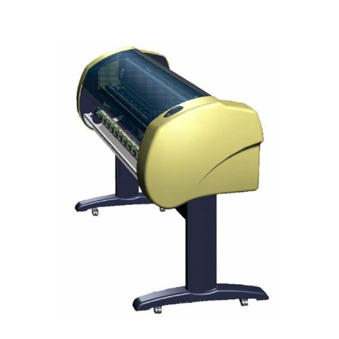
GCC Technologies J5 Series User manual

Version : 9.0
1
J5 & J5 LX Series
Maintenance Manual

Version : 9.0
2
Table of Contents
Chapter 1:Overview ..................................................................................................................... 3
1.1 Introduction ......................................................................................................................... 3
Chapter 2:Mechanical System ................................................................................................. 4
2.1 Main Unit Assembly ........................................................................................................... 5
2.2 Left End Assembly ............................................................................................................. 8
2.3 Right End Assembly ........................................................................................................ 10
2.4 Motor Bracket and Belt Assembly ................................................................................. 12
2.5 Carriage Assembly ........................................................................................................... 14
2.6 LX Carriage Assembly (AAS) ......................................................................................... 16
2.7 Pinch Roller Assembly .................................................................................................... 19
2.8 Main Beam Assembly ...................................................................................................... 21
2.9 Drum Assembly ................................................................................................................ 23
Chapter 3:Circuit System ........................................................................................................ 25
3.1 System Diagram ............................................................................................................... 25
3.2 J5 Wiring Diagram ........................................................................................................... 25
Chpater 4 Maintenance ............................................................................................................... 28
4.1 Components Replacement and Belt Tension Adjustment ......................................... 28
4.1.1 Removing the Front, Back, End and Top Covers ............................................. 28
4.1.2 Replacing the Pinch Roller Sets ......................................................................... 30
4.1.3 Replacing the Tool Carriage ............................................................................... 32
4.1.4 Replacing the
Y-Motor
.......................................................................................... 36
4.1.5 Replacing the VCM PC Board............................................................................. 38
4.1.6 Main board Connection or Replacement ........................................................... 39
4.1.7 Replacement
of Fuses ......................................................................................... 39
4.1.8 Adjusting the Tool Carriage
Transmission Belt
................................................. 40
4.1.9 Adjusting the X Motor Tension Belt .................................................................... 41
4.1.10 Adjusting the Y Motor Tension Belt .................................................................. 42
Chapter 5. Troubleshooting ....................................................................................................... 44
5.1 Maintenance Diagnostics ................................................................................................ 44
5.1.1 How to Begin
Maintenance Diagnostics
............................................................ 44
5.1.2 Diagnostic Test for SRAM and DRAM ............................................................. 46
5.1.3 Diagnostic Test for Lever Sensor .................................................................... 46
5.1.4 Diagnostic Test for Media Sensors .................................................................. 47
5.1.5 Diagnostic Test for Width Sensor .................................................................... 48
5.1.6 Diagnostic Test for Motor Encoder and Tool Holder Encoder ..................... 49
5.1.7 Y Motor Encoder Test ....................................................................................... 50
5.1.8 Diagnostic Test for Tool Force (VCM) ............................................................ 50
5.1.9 Diagnostic Test for Motor Movement .............................................................. 50
5.1.10 Diagnostic Test for the RS-232 Interface ........................................................ 52
5.2 Problems and Solutions .................................................................................................. 53
5.3 Firmware update .............................................................................................................. 56
Chapter 6 Appendix ..................................................................................................................... 58
6.1 Recommended Parts and Accessory List .................................................................... 58


Version : 9.0
3
Chapter 1:Overview
1.1 Introduction
This manual is prepared for distributors to maintain or repair Auto feeder. Briefly,
Chapter 1
System overview
Chapter 2
We have diagrams to show the part number for every part in different sections.
Chapter 3
Circuit System, there is detailed information for the connection circuits.
Chapter 4
Introduction to show you how to replace parts.
Chapter 5
Trouble shooting & System Diagnostics
Chapter 6
We have the parts list to show the part no. of difference size of J5 series.
Manual contents may be subject to change without notice. Please contact GCC Customer
Service
by calling at 886-2-2694-6687 or e-mailing to tech.support@gccworld.com for services.

Version : 9.0
4
Chapter 2:Mechanical System
We will have diagrams to show the part number for every part in the following sections.
They are:
Main unit
Left End Assembly
Right End Assembly
X Motor Bracket and Belt Assembly
Carriage Assembly
LX Carriage Assembly
Pinch Roller Assembly
Main Beam Assembly
Drum Assembly

Version : 9.0
5
2.1 Main Unit Assembly

Version : 9.0
6
Main Unit Assembly – Parts List
No.
Part No. Description QTY
1 20600051G Y axis carriage belt (2GT-L3366-W14) 1
2 22801068G Square bar 1
3 22801149G Top Rail 1
4 22801466G White Bush 0604 2
5 234000410G Control Panel Sticker 1
6 23500005G Nut(M4xt3.2xS7) 11
7 241006780G Front platen extension 132 1
8 241006810G Rear platen extention 132 1
9 24100247G Right cover Jaguar.(Black) 1
10 24100246G Left cover Jaguar.(Black) 1
11 24100253G Shift-Lever Cam 1
12 24100237G Control panel base (Black) 1
13 24100311G Lever 1
14 24400048G Square bar bracket 1
15 244053900G Top cover 132 1
16 24400759G Main beam support 3
17 244053520G Jaguar V 132 Base Unit 1
18 24900002G E-shape retaining ring.D11*d5*t0.6 3
19 25200003G panhead machine screw(white) M3*8 2
20 25200006G Socket headness set screw.(M3*5L) 1
21 25200115G Truss head machine screw(M3*6L SUS) 36
22 25200122G 90° dish flat head machine screw M3*8 2
23 25200129G Truss head machine screw & spring washer M3*8. 3
24 25200181G Truss head machine screw(M4*6L) 10
25 25200198G Truss head machine screw(M4*8L) 2
26 25200199G Truss head screw including external teech washer 4
27 25200237G Socket head set screw.(M4*16L sus+coating) 14
28 25200253G Socket head set screw.(M4*30L) 6
29 26000006G Spring washer. (d4xD7xt0.8)NI 14
30 26000008G Plastic washer 8
31 26000010G Nylon washer U-7 2
32 26000026G External toothed lock washer (M4-Ni) 2
33 290094210G Carriage stopper Assembly. 1
34 29002348G Pinch roller Assembly 4
35 290094062G Carriage assembly for J5LX (from S/N:S80000) 1
36 290094190G Control Panel Board assembly with 8051 English LCM
Firmware 1

Version : 9.0
7
No.
Part No. Description QTY
37
290107330G MainBoard with J5-61 Firmware (from S/N S70549) 1
290107340G Mainboard with J5-101 Firmware (from S/N R88284) 1
290107350G Mainboard with J5-132 Firmware (from S/N S70664) 1
290107410G Mainboard with J5-101LX Firmware (from S/N R88289) 1
290107420G Mainboard with J5-132LX Firmware (from S/N R70069) 1
290107430G Mainboard with J5-183LX Firmware (from S/N R88374) 1
38 29006251G Main Beam Assembly 1
39 290077800G DC Motor Driver Board Assembly with L6203 1
40 24500083G 250W Isolated Dual Output with PFC(Power Factor Correction)
Function(PID-250C) 1
41 244060280G cover 1
No.
Part No. Description QTY
S8 209027600G
Simple Cattle Horn Female 2*20P to Simple Cattle
Horn Female 2*20P Cable L:80mm 1
S9 209027600G
Simple Cattle Horn Female 2*20P to Simple Cattle
Horn Female 2*20P Cable L:80mm 1
S14
209023150G
Lever SW to M/B Cable330mm 1
S15
290099990G
Touch Key sensor control board to Main Board
Cable Assembly 1
No. Part No. Description QTY
Remark
S1 209026810G
Motor Driver cable 3.96-2pin 160mm 1
S2
20901915G Motor Driver cable 3.96-2pin 1100mm 1 J5-61
20901913G Motor Driver cable 3.96-2pin 1900mm 1 J5-132
20901912G Motor Driver cable 3.96-2pin 2400mm 1 J5-183
S3 20901911G Power Board to Motor Driver Board Cable 650mm 1 J5-61, J5-132
20901976G Power Board to Main Board Cable 1350mm (1001182) 1 J5-183
S4 209026890G
Motor Encoder Cable 2.54-4PIN 110mm 1
S5
209023200G
Motor Encoder Cable 2.54-4PIN 1100mm 1 J5-61
209023170G
Motor Encoder Cable 2.54-4PIN 1600mm 1 J5-132
209023190G
Motor Encoder Cable 2.54-4PIN 2400mm 1 J5-183
S6 209023120G
2.54-3Pin Motor Driver Board to Paper Sensor Cable 600mm 1 J5-61, J5-132
209027850G
Rear Paper Sensor Cable1050mm 1 J5-183
S7 209023120G
2.54-3Pin Motor Driver Board to Paper Sensor Cable 600mm 1 J5-61, J5-132
209027860G
Front Paper Sensor Cable1050mm 1 J5-183
S8 209027600G
Simple Cattle Horn Female 2*20P to Simple Cattle Horn
Female 2*20P Cable L:80mm 1
S9 209027600G
Simple Cattle Horn Female 2*20P to Simple Cattle Horn
Female 2*20P Cable L:80mm 1
S10
290108300G
Flat cable assembly (30cm) 1
S11
209023130G
Fan Cable 80mm 1 J5-61, J5-183
209023130G
Fan Cable 80mm 2 J5-132

Version : 9.0
8
2.2 Left End Assembly

Version : 9.0
9
Left End Assembly – Parts List
No.
Part No. Description QTY
1 20600007G
Y-axis belt. 2GT-L172-W10 1
2 22000149G
P.C.B interval pillar (LCA4-10A) 2
3 22801359G
Y-axis Motor Spacer 3
4 23800032G
Motor board. (12258) 1
5 24400039G
Pully bottom bracket 1
6 24400041G
Y-motor bracket 1
7 24400526G
Pully top bracket 1
8 24400755G
Side support left 1
9 25200052G
Pan head machine screw including spring washer 4
10 25200182G
Truss head screw including external teech washer 2
11 25200196G
Truss head machine screw including spring washer 3
12 25200233G
Truss head machine screw(M4*15L). 3
13 25200245G
Truss head machine screw including spring washer 1
14 26000004G
Flat washer. (d4.4xD10xt0.8 NI) 1
15 29000936G
Active Gear Assembly 1
16 29001804G
Motor Assembly 1

Version : 9.0
10
2.3 Right End Assembly
290106350G Flat cable 9 pin to 8 pin PCB Assembly

Version : 9.0
11
Right End Assembly – Parts List
No.
Part No. Description QTY
1 20600039G
X-axis belt (2GT-L240-W10) 1
2 22000149G
P.C.B interval pillar (LCA4-10A) 2
3 24400038G
X-motor adjusting bracket 1
4 244060930G
Cable basket 1
5 24400304G
Ideal pulley ass y bracket 1
6 24400715G
Idel pulley Assembly adjusting bracket 1
7 24400757G
Right Side Plate 1
8 24400761G
X-motor bracket 1
9 25200017G
Truss head machine screw(M3*15L).black 2
10 25200052G
Pan head machine screw including spring washer 4
11 25200117G
HexagonalSocketHead including spring&flat washer(M3*8L) 2
12 25200157G
HexagonalSocketHead including spring&flat washer(M3*16L) 1
13 25200181G
Truss head machine screw(M4*6L) 2
14 25200182G
Truss head screw including external teech washer 4
15 25200208G
Truss head screw including spring & flat washer(M4*10) 6
16 25200245G
Truss head machine screw including spring washer 1
17 25700002G
Lever Switch (VM3-04N-80S-U3 (390)) 1
18 29000560G
Y idel pulley assembly 1
19 29001804G
Motor Assembly 1
290106350G Flat cable 9 pin to 8 pin PCB Assembly
No.
Part No Description QTY
S10
290108300G Flat cable assembly (30cm) 1
S12
290108340G Flat cable Assembly for 61 model (1050mm) 1
290108320G Flat cable assembly for 132 model (1830mm) 1
290108310G Flat cable assembly J5-183.(2250mm) 1

Version : 9.0
12
2.4 Motor Bracket and Belt Assembly

Version : 9.0
13
No.
Part no.
De
s
c
r
i
p
t
i
o
n
Qty
6
29001804G Motor assembly, Jaguar.
1
6.1.1 23100014G Motor MS090600, Jaguar.
1
6.1.2 21700009G Motor pulley, 2GT-P18, Jaguar.
1
6.1.3 25200169G Headless Screw, M4x3.5.
1
6.1.4 22000107G Cable Tie, YJ-160.
1
6.2
24400761G X-motor bracket, Jaguar.
1
6.3
24400038G X-motor adjusting bracket, Jaguar.
1
6.4
25200245G Truss head screw & spring washer, M4x20.
1
6.5
25200208G Truss head screw & spring & flat washer,
6
6.6
25200052G Pan head screw & spring washer, #6x8.
4
Motor Bracket and Belt Assembly – Parts List

Version : 9.0
14
2.5 Carriage Assembly

Version : 9.0
15
Carriage Assembly – Parts List
No.
Part No. Description QTY
1 20200071G
Blade holder slide bracket assembly 1
2 20700029G
Bearing 4
3 21700034G
Y-axis belt bracket 1
4 22000036G
Cable saddle (YL-1) 1
5 22800410G
Carrier guide roller(DU type) 4
6 22800411G
Spacer for carrier guide roller(DU type) 2
7 22800769G
Right-Slide shaft in tool carriage. 1
8 22800767G
Carrier guide roller(DU type)shaft 2
9 22800769G
Right-Slide shaft in tool carriage. 1
10 22800838G
Blade holder bracket screw 1
11 24100054G
Spring bracket for carrier guide roller 4
12 22802197G
carriage base finishing(Jaguar IV) 1
13 23300824G
Cable Fix 1
14 23500005G
Nut(M4xt3.2xS7) 2
15 24100307G
Carriage plastic cover 1
16 24400400G
Encoder grid bracket 1
17 24700073G
O-Ring(d3.5*t2.0) 2
18 24700044G
O-Ring(d2.0*r1.5) 1
19 25200004G
Pan head machine screw(M2.6*6L) 2
20 25200008G
Socket head set screw.(M3*6L)while+coating 2
21 25200017G
Truss head machine screw(M3*15L).black 2
22 25200048G
Pan head machine screw.M3*5 2
23 25200049G
Pan head machine screw.M3*6 2
24 25200059G
Pan head machine screw(M2*4L) 2
25 25200065G
Pan head machine screw including flat washer.(2*6) 6
26 25200093G
Pan head machine screw(M3*4L black) 2
27 25200107G
Pan head machine screw including spring washer. 1
28 25200112G
Truss head screw including flat washer 2
29 25500041G
Spring for carrier guide roller 2
30 25500043G
Tool carriage spring 2
31 25600019G
VCM Encoder grid 1
32 26000003G
Flat washer. (d2xD4xt0.4 NI) 2
33 26000009G
Spring washer.(d3xD5.3x0.7 Ni) 2
34 290072830G
A roller Assembly 2
35 29000940G
VCM Assembly. 1
36 29001802G
Encoder PCB Assembly. 1
37 290110320G
AAS II carriage board Assembly(with firmware) 1
38 29005382G
AAS II sensor assembly with braket 1

Version : 9.0
16
2.6 LX Carriage Assembly (AAS)

Version : 9.0
17
LX Carriage Assembly – Parts List
No.
Part No. Description QTY
1 20200071G
Blade holder slide bracket assembly 1
2 20700029G
Bearing 4
3 21700034G
Y-axis belt bracket 1
4 22000036G
Cable saddle (YL-1) 1
5 22800410G
Carrier guide roller(DU type) 4
6 22800411G
Spacer for carrier guide roller(DU type) 2
7 22800769G
Right-Slide shaft in tool carriage. 1
8 22800767G
Carrier guide roller(DU type)shaft 2
9 22800769G
Right-Slide shaft in tool carriage. 1
10 22800838G
Blade holder bracket screw 1
11 24100054G
Spring bracket for carrier guide roller 4
12 22802197G
carriage base finishing(Jaguar IV) 1
13 23300824G
Cable Fix 1
14 23500005G
Nut(M4xt3.2xS7) 2
15 24100307G
Carriage plastic cover 1
16 24400400G
Encoder grid bracket 1
17 24700073G
O-Ring(d3.5*t2.0) 2
18 24700044G
O-Ring(d2.0*r1.5) 1
19 25200004G
Pan head machine screw(M2.6*6L) 2
20 25200008G
Socket head set screw.(M3*6L)while+coating 2
21 25200017G
Truss head machine screw(M3*15L).black 2
22 25200048G
Pan head machine screw.M3*5 2
23 25200049G
Pan head machine screw.M3*6 2
24 25200059G
Pan head machine screw(M2*4L) 2
25 25200065G
Pan head machine screw including flat washer.(2*6) 6
26 25200093G
Pan head machine screw(M3*4L black) 2
27 25200107G
Pan head machine screw including spring washer. 1
28 25200112G
Truss head screw including flat washer 2
29 25500041G
Spring for carrier guide roller 2
30 25500043G
Tool carriage spring 2
31 25600019G
VCM Encoder grid 1
32 26000003G
Flat washer. (d2xD4xt0.4 NI) 2
33 26000009G
Spring washer.(d3xD5.3x0.7 Ni) 2
34 290072830G
A roller Assembly 2
35 29000940G
VCM Assembly. 1
36 29001802G
Encoder PCB Assembly. 1
37 290110320G
AAS II carriage board Assembly(with firmware) 1
38 29005382G
AAS II sensor assembly with braket 1

Version : 9.0
18
No.
Part No. Description QTY
S12
290108340G
Flat cable Assembly for 61 model (1050mm) 1
290108320G
Flat cable assembly for 132 model (1830mm) 1
290108310G
Flat cable assembly J5-183.(2250mm) 1
S13
20901523G AAS II Sensor PCB to carriage PCB 1
S16
20900128G Cable (from VCM Encoder to tool carriage) 1
S17
20900430G VCM Board to Carriage Board Cable (1.5*5pin soft cabe 12cm) 1

Version : 9.0
19
2.7 Pinch Roller Assembly

Version : 9.0
20
Pinch Roller Assembly – Parts List
No. Part No. Description QTY
1 20200003G Pinch roller wheel 1
2 21700010G Releasing arm 1
3 22800028G Pinch roller active arm shaft 1
4 22800029G Pinch roller shaft 1
5 22800030G Releasing arm shaft 1
6 22800031G Blocking arm shaft 1
7 24100142G Blocking arm 1
8 24100268G Pinch roller base 1
9 24100276G CAM roller 1
10 24100355G Pinch roller active arm 1
11 241005730G Sensor Sheet 1
12 26500080G Indexer fixture.JT-1N. 1
13 24900001G E-shape retaining ring.d2*D5*t0.4 4
14 24900006G E-shape retaining ring.(D7*d3*t 0.6) 4
15 25500013G Blocking arm spring 1
16 25500014G Sensor indexer Spring. 1
17 25500039G Pinch Roller Spring 2
18 26000001G Plastic washer.WS-1M 2
This manual suits for next models
1
Table of contents
Other GCC Technologies Plotter manuals

GCC Technologies
GCC Technologies puma iii series User manual

GCC Technologies
GCC Technologies BENGAL User manual

GCC Technologies
GCC Technologies Jaguar IV Series User manual

GCC Technologies
GCC Technologies P3-60 User manual

GCC Technologies
GCC Technologies Jaguar V Series User manual

GCC Technologies
GCC Technologies EXPERT 24 LX User manual

GCC Technologies
GCC Technologies EXPERT 24 LX User manual

GCC Technologies
GCC Technologies EP-60 User manual

GCC Technologies
GCC Technologies AR-24 User manual

GCC Technologies
GCC Technologies Jaguar II Series User manual