HIPOTRONICS OC-DI Series User manual
I
Operating Instructions
OC-DI Series
Digital Interface
Oil Testers
Version 1.0
No. 145896

II
Title
Digital Interface Oil Testers
Date
06/2018
Revision History
V0.1
03/2018
MC
Initial draft of the document

III
This equipment contains exposed terminals carrying hazardous
voltages. There are no user serviceable components in the unit.
All repairs and upgrades that require the unit to be opened must
be referred to HIPOTRONICS or one of their nominated agents.
HIPOTRONICS and its sales partners refuse to accept any responsibility for consequential or
direct damage to persons and/or goods due to the lack of observance of instructions contained
herein or due to incorrect use of the equipment.
Further be aware that safety is the responsibility of the user!
Any correspondence regarding this instrument should include the exact type number,
instrument serial number and firmware version number. With the exception of the firmware
version number, this information can be found on the registration plate on the right panel of the
instrument. The firmware version can be found in the bottom right corner of the settings window.
Unauthorized opening of the unit may damage the EMI protection of the system and will reduce
its resistance to interference and transients. It may also cause the individual unit to be no longer
compliant with the relevant EMC emission and susceptibility requirements. If the unit has been
opened, the calibration will be rendered invalid and the warranty will be void.
Note
HIPOTRONICS has a policy of continuing improvement on all their products. The design of this
instrument will be subject to review and modification over its life. There may be small
discrepancies between the manual and the operation of the instrument, particularly where
software has been upgraded in the field.
HIPOTRONICS retains the right to modify the functionality, specification or operation of the
instrument without prior notice.
©All rights reserved. No section of this manual may be reproduced in any form, mechanical or
electronic without the prior written permission of HIPOTRONICS.
2018, HIPOTRONICS, USA
WARNING
Before operating the instrument, be sure to read and fully
understand the operating instructions. This instrument produces
hazardous voltages. It is the responsibility of the user to ensure
that the system is operated in a safe manner.

IV
Manual Conventions
In the manual, the following conventions are used:
Indicates hazards.
There is a risk of equipment damage or personal injury or death. Carefully read and follow
the instructions. Be sure to follow any safety instructions given in addition to those for the
site at which tests are being performed.

V
Foreword
Welcome, new user of the “OC-DI Series”. Thank you for placing your confidence in our
product.
With the purchase of this measuring instrument you have opted for all the advantages that have
built a world-wide reputation for a HIPOTRONICS Instrument: robustness, performance and
quality. As a result, this instrument provides a solution which achieves the optimal combination
of traditional know-how and leading edge technology.
This operating manual is designed for completeness and easy location of the required
information. Customers who already have experience with this kind of equipment will find this
document to be of assistance as an extended help.
If you find a mistake or inconsistency in the operating manual then please feel free to inform our
Customer Support department with your corrections so that other users may benefit.

VI
Contents
Manual Conventions IV
1Introduction 8
1.0 Receiving Instructions.................................................................................. 8
1.1 General........................................................................................................ 8
1.2 Scope of Supply........................................................................................... 8
1.2.1 Standard Scope of Supply............................................................... 8
1.3 Technical Data: OC60-DI............................................................................. 9
1.3.1 Physical and Environmental Specifications..................................... 9
1.3.2 Measurement .................................................................................. 9
2Safety 10
2.0 General...................................................................................................... 10
2.1 Essential Safety Recommendations .......................................................... 10
2.2 Summary.................................................................................................... 11
3Theory 12
3.0 Introduction................................................................................................ 12
3.1 Pre-Loaded Test Standards....................................................................... 12
3.2 Application ................................................................................................. 12
4Oil Tester Ports 13
4.0 Ports .......................................................................................................... 13
5Connection and Setup 14
5.0 Ground Connections.................................................................................. 14
5.1 Prepare Oil Test......................................................................................... 14
5.2 Main Menu................................................................................................. 15
5.3 Basic Mode................................................................................................ 16
5.4 Multi-Step Mode......................................................................................... 18
5.5 Reports ...................................................................................................... 20
5.6 Settings...................................................................................................... 21
6Troubleshooting 22
6.0 Diagnostics ................................................................................................ 22
6.1 Warning and Error Messages .................................................................... 22
7Miscellaneous 23
7.0 Care and Maintenance............................................................................... 23
7.0.1 Cleaning the Instrument................................................................ 23
7.0.2 Instrument Calibration................................................................... 23

VII
7.1 Instrument Storage .................................................................................... 23
7.2 Packing and Transport............................................................................... 24
7.3 Recycling ................................................................................................... 24
8Customer Support 25
9Appendix 26
9.0 Declaration of Conformity........................................................................... 26
9.1 Hipotronics, Inc.......................................................................................... 26
9.2 Warranty .................................................................................................... 27
9.3 Returned Material (RMA)..............................Error! Bookmark not defined.

8
1 Introduction
1.0 Receiving Instructions
When received, any possible transport damage should be noted. A written record should be made of
any damage. A suitable remark should be recorded on the delivery documents.
A claim for damage must be reported immediately to the transport company and to the Customer
Support Department of HIPOTRONICS or the local agent. It is essential to retain the damaged
packing material until the claim has been settled.
Check the contents of the shipment for completeness immediately after receipt (See chapter “Scope
of Supply”). If the shipment is incomplete or damaged, then this must be reported immediately to the
transport company and the Customer Support Department of HIPOTRONICS or the local agent.
Repair or replacement of the instrument can then be organized immediately.
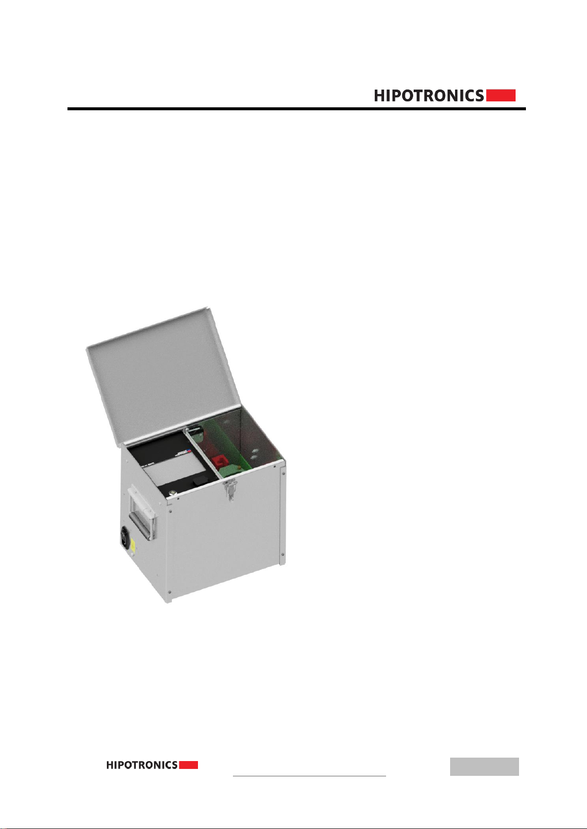
1.1 General
The OC60-DI Liquid Dielectric Tester accurately and reliably tests dielectric strength of insulating
liquids used in a wide variety of electrical apparatus. The rugged, lightweight and portable design
ensures years of safe and trouble-free operation both in the field and in the laboratory.
1.2 Scope of Supply
1.2.1 Standard Scope of Supply
The following items are supplied with the standard instrument:
Qty
Description
1
Oil Tester Instrument
1
Power Cord
1
Operation Manual in English
1
Calibration Certificate

1 Introduction
9
1.3 Technical Data: OC60-DI
1.3.1 Physical and Environmental Specifications
Operating temperature
14…122° F (-10 .. 50°C)
Storage temperature
-4…158° F (-20 .. 70°C)
Humidity
5 ... 95 % r.h. non-condensing
Dimensions (W x D x H)
OC60-DI: 16” x 13” x 15” (41cm x 33cm x 38cm)
Weight
OC60-DI: 60lbs (25kg)
1.3.2 Power Specifications
Power Input
90 –264VAC 50 or 60Hz 200VA
Battery Power
12VDC NiMH 8.4Ah
1.3.3 Measurement
Breakdown Voltages
Accuracy: +/- 2% F.S.
Resolution: 0.1kV
Voltmeter
Accuracy: +/- 1% F.S.
Resolution: 0.1kV

10
2 Safety
Remember:
Hazardous voltage can shock, burn or cause death !
The unit should only be operated after carefully reading the user manual, which is an
integral part of the instrument.
HIPOTRONICS and its sales partners refuse to accept any responsibility for consequential
or direct damage to persons and/or goods due to none observance of instructions
contained herein or due to incorrect use of the equipment.
Further be aware that Safety is the responsibility of the user!
2.0 General
Safety is the most important aspect when working on or around high voltage electrical equipment.
Personnel whose working responsibilities involve testing and maintenance of the various types of high
voltage equipment must have understood the safety rules written in this document and the associated
safety practices specified by their company and government. Local and state safety procedures
should also be consulted. Company, regional or national regulations must be fulfilled beyond
HIPOTRONICS recommendations.
If the instrument is damaged or it is possible that damage has occurred, for example during
transportation, do not apply any voltage. The instrument may only be used under dry operating
conditions.
Do not open the unit; it contains no user replaceable parts.
People with heart pacemakers should not be in the vicinity of this system during operation.
Safety is the responsibility of the user. Always operate the equipment in accordance with
the instructions, always paying full attention to local safety practices and procedures.
This equipment must be operated only by trained and competent personnel who are aware
of the dangers and hazards involved in testing transformers.
2.1 Essential Safety Recommendations
Every terminal should be checked and verified before connection of the instrument. Ground
connections may be left in place.

2 Safety
11
Never operate the equipment in an explosive environment or where there are flammable
gases or fumes
The instrument must always be connected to a grounded power outlet (i.e. a safety earth).
It must never be operated in a non-grounded configuration as this may result in electrical
shock to the user or damage to the instrument.
2.2 Summary
Note: Many accidents that happen around high voltage equipment involve personnel who are not
familiar, or perhaps too familiar, with high voltage equipment. Staying alert and ever watchful requires
constant training and awareness of the inherent hazards. The greatest hazard is the possibility of
getting on a live circuit. To avoid this requires constant vigilance - for oneself and for one's fellow
workers.
In addition to the obvious dangers, personnel should be alert to recognize subtle dangers as well.
Therefore, all terminals of a device under test, unless grounded, should be considered to be
live while the test is in progress.
Remember: Safety, FIRST, LAST, and
ALWAYS !

12
3 Theory
3.0 Introduction
This model is designed to meet testing specifications from all parts of the world with test cells
available for ASTM D877, ASTM D1816 and IEC 156 testing standards. The OC60-DI offers the
ability to use one of the pre-programmed rates of voltage rise or allows the operator to create their
own tests using Basic mode. An internal kilovoltmeter automatically records the breakdown
voltage for each test sample. Each test can be saved into the unit’s internal memory or to a USB
drive.
3.1 Pre-Installed Test Standards
ASTM D877A NF EN 60156
ASTM D877B UNI EN 610156
ASTM D1816 SABS EN 60156
IRAM 2341 PA SEV EN 60156
JIS C 2101 (M) / (S) CEI EN 60156
AS1767.2.1 BS EN 60156
VDE 0370 IEC 60156
3.2 Application
Testing of insulating dielectric liquid that are used in :
▪Transformers
▪Bushings
▪Switchgear
▪Capacitors
▪Hydraulics

4 Oil Tester Ports
13
4 Oil Tester Ports
4.0 Ports
LCD Touchscreen Interface: Use to control software to setup and implement oil tests
Mains Input: Insert power cord to power or recharge unit. When charging, make sure that the input
switch is in the ‘ON’ position
Ground Terminal: Connect chassis to proper ground
Power Button: Turn on/off unit interface. When the unit is on, the power symbol on the button will be
lit up green. To turn off the interface, press and hold the power button for a couple of seconds
USB Port: Insert USB drive to export test data

14
5 Connection and Setup
5.0 Ground Connections
First make sure to connect the unit to a proper ground through the ground screw located on the
left side of the oil tester.
5.1 Prepare Oil Test
Make sure the oil cup is properly cleaned twice before each oil sample test to ensure accurate
results. Fill the oil cup with the specified amount according to the standard being tested to. Carefully
place the oil cup into the slot holders of the transformer inside the test chamber.
6 Operating Modes
15
6 Operating Modes
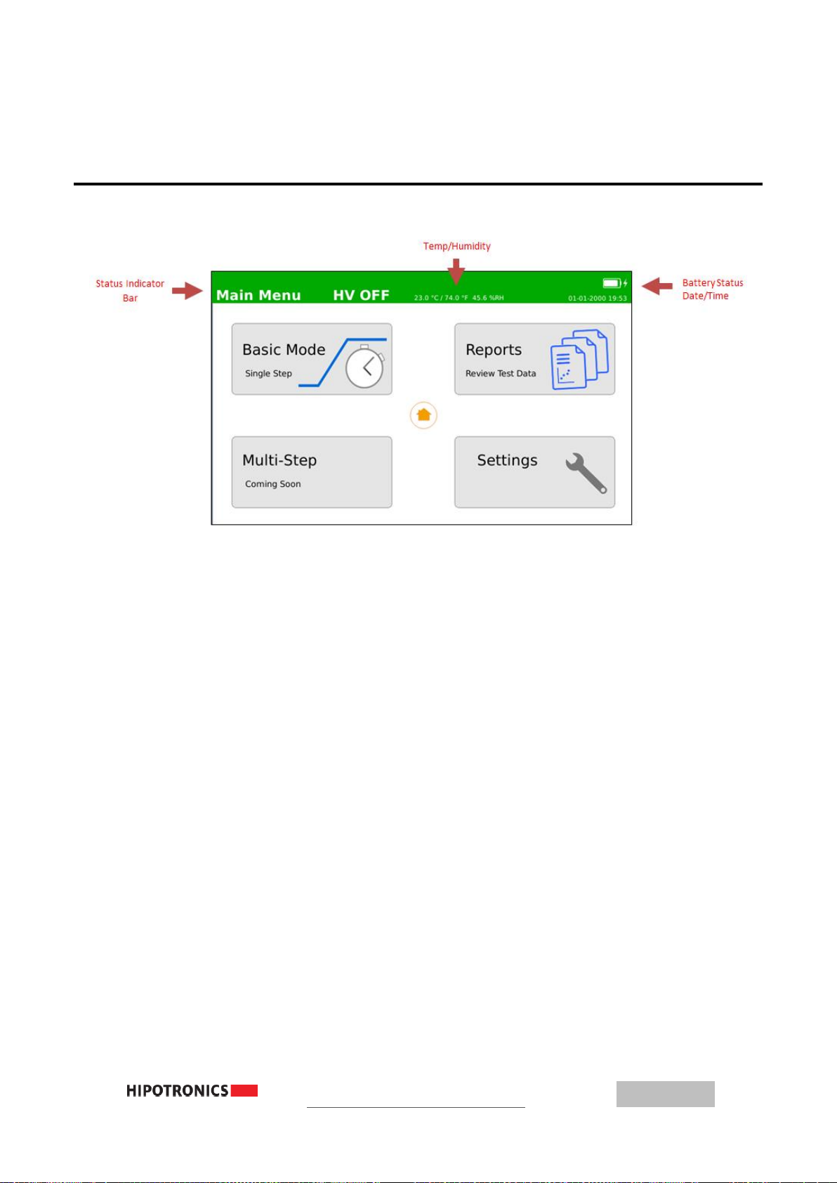
6.0 Main Menu
Upon turning the unit on, the interface will load to the Main Menu window. The top bar is the
status indicator at all times. It will be green when high voltage is off, and red when high voltage is on.
The left corner of the bar will display what window is currently displayed. In the center, the temperature
and humidity will be shown; and in the right corner will be the battery level status, and the current
date/time.
There are four windows that you can access from the Main Menu window. Basic Mode is the
standard automatic oil test that ramps up to a desired voltage until breakdown. Multi-Step is a custom
test where the user can program several ramping stages. Reports will allow the user to view and export
previously saved tests. Lastly, in the Settings window, the user can configure basic test or system
parameters.

16
6.1 Basic Mode
Although Basic Mode is the simple automatic ramping oil test, the user now has the ability to set
many different parameters and options to make the test as easy and hands-free as possible.
If testing to a common industry standard, the user can select the clipboard icon to view a list of
pre-loaded standards that will automatically populate all of the parameter fields for that test. The right
half of the window will show a visual of the test voltage sequence.
To edit the parameters, click on the buttons on the left half of the window or on the bottom bar.
The number of tests dictates how many times the unit will ramp up voltage in one test sequence. The
ramp rate will set how fast the voltage increases during the test. The wait time is the period between
each individual breakdown test, and the dwell time is the period that the voltage will hold at when it
reaches its maximum limit without a breakdown occurring.
The OC60-DI also has an Ethernet port in the HV chamber where you can plug in the motor
stirrer accessory. This Ethernet port will provide power to the motor stirrer if the stir option is selected,
and a test is running. The user can also select the type of electrode being used with the test, for
reference that will be saved in the report.
The last two parameter buttons on the right side of the bottom bar will allow the user to select
the maximum voltage that the unit will ramp to, up to 60kV; and the output frequency of the high voltage
waveform.
6 Operating Modes
17
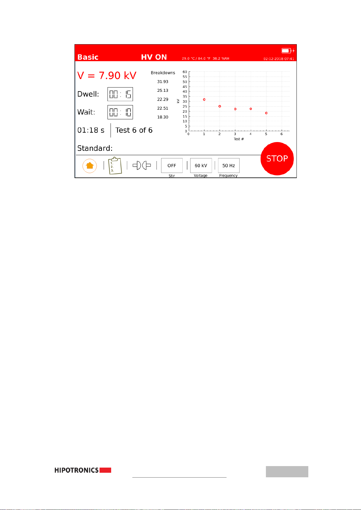
After pressing the ‘START’ button, the chosen test sequence will commence, and a new
window will show all of the test parameters. The high voltage will ramp up to the selected target voltage,
at the selected ramp rate, and then remain at that voltage for the chosen dwell time. Once the dwell
time expires, or a breakdown occurs, the test will shut off high voltage and wait for the selected wait-
time before starting a next ramp test, (if they were multiple number of tests selected). The voltage
measurement in the top left will show the real-time voltage across the electrodes. The dwell and wait
time counters will always be displayed, and will count down when they are active. The total elapsed test
time and the current test number are shown in the bottom left.
The right half of the test screen will display the breakdown voltages and graph them on a plot. If
the test chamber cover is opened at any time during a test, the high voltage output will shut off and the
test will pause until the lid is closed again.
At the conclusion of a test sequence, a small window will pop-up showing a summary of the
test, and the user can either save the test data to a report, or press ‘Ok’ to return to the original basic
mode window.

18
6.2 Multi-Step Mode
In Multi-Step mode, each test has the capability to customize multiple ramping sequences for
unique testing scenarios. By clicking on the cells in the table, the user can select the ramp rate, target
voltage, and dwell time for each sequence in the test. To add a step in the test sequence, click the ‘plus-
sign cell’ at the bottom of the table, and then click each cell in the row to select the parameters for that
step. To remove the last step in the sequence, click the ‘x-button’ in the bottom left of the table. The
sequence table will only ever show three steps at a time; to view the other steps currently in the test
sequence, scroll up or down with the ‘arrow keys’ to the right of the table.
Similar to Basic Mode, you can adjust other test parameters on the bottom of the screen, such
as electrode type, stir option, number of ramp tests to be cycled, the wait time in between tests, and the
output frequency. Once, all of these options are selected, begin the test sequence by clicking the
‘START button’.
6 Operating Modes
19
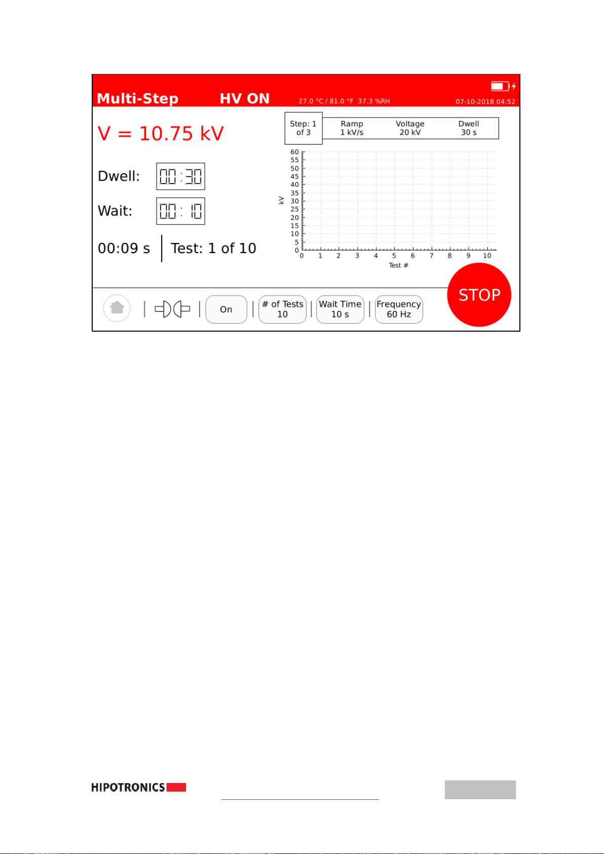
During a test sequence, the left side of the screen will display similar information to Basic Mode
(see Section 5.3 for detailed information). The right side of the screen will display all of the breakdowns
for the test cycle, and the current step in the sequence. At the start of the test, the voltage will ramp up
to the first step’s target voltage, at the selected ramp rate, and then dwell at that voltage for the selected
dwell time. Once that step’s dwell expires, the voltage will start ramping up to the next step’s target
voltage, at the next step’s selected ramp rate, and then proceed to dwell. This will continue until all of
the steps in the sequence have been performed, or a breakdown occurs. High voltage will be shut off,
and the unit will wait for the chosen wait-time before commencing another test, if multiple number of
tests were selected.
20
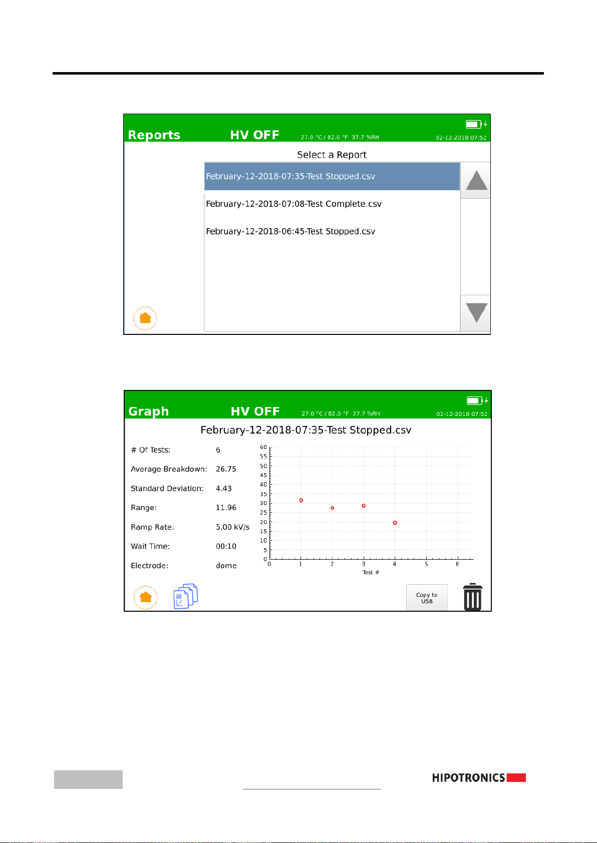
6.3 Reports
In the Reports window, all of the previously saved test data will be in a report labelled by its date and time
of test. Use the touchscreen to select a report to view.
When viewing a report on the unit, several of the chosen test parameters will be displayed, along with the
calculated average breakdown voltage, standard deviation of the breakdowns, the breakdown range, and a
graph of the breakdowns. The user can also export the test report to a USB drive that is inserted into the unit’s
USB port, and press the ‘Copy to USB’ button. The exported report will contain more information, such as
each breakdown, the frequency, stir, and temperature/humidity during the test.
This manual suits for next models
1
Table of contents
Other HIPOTRONICS Test Equipment manuals


