GENERAL INSTRUCTIONS
These instructions should be read carefully and retained after installation by the end
user for future reference and maintenance.
These instructions should be used to aid installation of the following products:
TE1 / TE2
SAFETY
• Do not use at voltages above 690V
• Do not use in the presence of flammable gases or in explosive environments
• The operator must keep hands and fingers behind the finger guards
• The instrument must be used with the probe safety covers in place
• Correct operation of the tester on a known voltage source must be checked before and after
measurements are taken
• Do not unlock or open the battery case during measurements
• Do not make any modifications to the instrument, or use if damaged
• This product is suitable for use only in a dry environment (<85% RH)
• Readings may be unreliable outside of the temperature range -10°C to 55°C (<85% RH). The
product should not be stored at temperatures outside of the range -20°C to 60°C
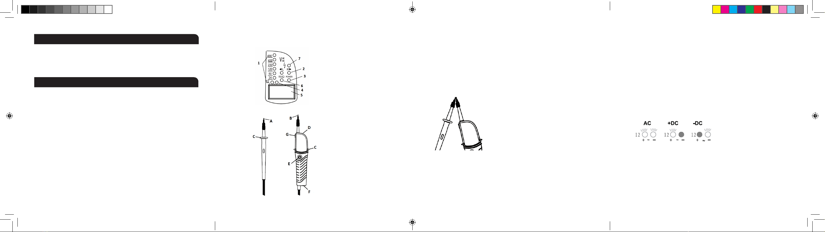
1 LEDs for voltage indication
2 L / R LEDs for phase rotation test
3 Power LED
4 Polarity indication for voltage test
5 LCD display (TE1 only)
6 Continuity LED
7 High voltage LED
LAYOUT BATTERY INSTALLATION
Unlock the battery case by inserting a coin or large flat-head screwdriver and twisting
anti-clockwise. Insert two AAA 1.5V batteries observing the polarity marked on the case.
Lock before use.
SELF-DIAGNOSTIC TEST
Touch the two probes together (see Fig. 1). The power LED will illuminate, and the sounder
should be heard. If the power LED flashes or turns off, the batteries may need replacing.
CONTINUITY TEST
Make sure the object under test is not live. Touch the two probes onto the two conductive parts
to be measured. The continuity LED will illuminate, and the sounder will be heard if continuity
is detected up to 550KΩ. Contact must be made with clean metal as corrosion, rust, grease, or
other debris on the measurement surfaces may affect the reading.
Fig. 2
PHASE ROTATION
For detection of phase rotation on three-phase systems, grasp the handle firmly - this is
necessary because the instrument uses capacitive coupling onto the user to achieve a zero-volt
reference. Therefore the user must be sufficiently connected to earth for this function to operate.
The phase rotation is indicated by the left and right arrows (see Fig. 3)
A Probe -
B Probe +
C Finger guards
D Torch
E Torch switch
F Battery compartment
G Probe clip
A Probe -
B Probe +
C Finger guards
D Torch
E Torch switch
F Battery compartment
G Probe clip
BATTERY INSTALLATION
Unlock the battery case by inserting a coin or large flat screwdriver and twisting anti-clockwise. Insert two AAA
1.5V batteries observing the polarity marked on the case. Lock before use.
SELF-DIAGNOSTIC TEST
Touch the two probes together (see Fig. 1). The power LED will illuminate, and the sounder should be heard. If
the power LED flashes or turns off, the batteries may need replacing.
Fig. 1
CONTINUITY TEST
Make sure the object under test is not live. Touch the two probes onto the two conductive parts to be measured.
The continuity LED will illuminate, and the sounder will be heard if continuity is detected up to 550KΩ. Contact
must be made with clean metal, as corrosion, rust, grease, or other debris on the measurement surfaces may
affect the reading.
VOLTAGE TEST
Correct operation of the tester on a known voltage source must be checked before and after measurements are
taken.
Place the two probes onto the conductive parts to be measured. The voltage is indicated by the LCD screen
(TE1 only), and by the voltage LEDs. The high voltage indication LED will begin to illuminate as the voltage
increases beyond approximately 50V.
POLARITY
AC polarity is not indicated. Both + and - indicators light up when connected to an AC source, regardless of the
polarity.
VOLTAGE TEST
Correct operation of the tester on a known voltage source must be checked before and after
measurements are taken.
Place the two probes onto the conductive parts to be measured. The voltage is indicated by the
LCD screen (TE1 only), and by the voltage LEDs. The high voltage indication LED will begin to
illuminate as the voltage increases beyond approximately 50V.
POLARITY
AC polarity is not indicated. Both + and - indicators light up when connected to an AC source,
regardless of the polarity.
DC polarity is indicated as follows (see Fig. 2): when the + probe is connected to a positive DC
source, the + indicator will illuminate. When the + probe is connected to the negative DC source,
the - indicator will illuminate.
Fig. 1
TE1_TE2_INSTRUCTIONS.indd 1-4TE1_TE2_INSTRUCTIONS.indd 1-4 29/04/2021 07:14:5429/04/2021 07:14:54


