HIPOTRONICS 800PL Series User manual

Operating Instructions
840PL-HD
800PL Series
DC HIPOT Testers
Version 1.3

Title
40kV DC Hipot High-Duty-Cycle
Date
01/2020
Authors
MC, MW, RO
Layout
Part number
840PL-HD
Revision History
V0.1
06/2019
MC
Initial draft of the document
V1.0
01/2020
MC
Released Version
V1.1
4/2020
MC
Changed operation software screenshots to new version
V1.2
10/2020
MC
Updated Specifications Page
V1.3
3/2023
MC
Added HIPODirect Section

WARNING
Before operating the instrument, be sure to read and fully understand
the operating instructions. This system produces and measures
hazardous voltages. It is the responsibility of the user to ensure that the
system is operated in a safe manner.
This equipment contains exposed terminals carrying hazardous voltages.
There are no user serviceable components in the unit. All repairs and
upgrades that require the unit to be opened must be referred to
HIPOTRONICS or one of their nominated agents.
HIPOTRONICS and its sales partners refuse to accept any responsibility for consequential or direct
damage to persons and/or goods due to the lack of observance of instructions contained herein or
due to incorrect use of the equipment.
Further be aware that safety is the responsibility of the user!
Any correspondence regarding this instrument should include the exact type number, instrument
serial number and firmware version number. With the exception of the firmware version number,
this information can be found on the registration plate on the right panel of the instrument. The
firmware version can be found in the bottom right corner of the settings window.
Unauthorized opening of the unit may damage the EMI protection of the system and will reduce its
resistance to interference and transients. It may also cause the individual unit to be no longer
compliant with the relevant EMC emission and susceptibility requirements. If the unit has been
opened, the calibration will be rendered invalid and the warranty will be void.
Note
HIPOTRONICS has a policy of continuing improvement on all their products. The design of this
instrument will be subject to review and modification over its life. There may be small discrepancies
between the manual and the operation of the instrument, particularly where software has been
upgraded in the field.
HIPOTRONICS retains the right to modify the functionality, specification or operation of the
instrument without prior notice.
©All rights reserved. No section of this manual may be reproduced in any form, mechanical or
electronic without the prior written permission of HIPOTRONICS.
2019, HIPOTRONICS, USA

Manual Conventions
In the manual, the following conventions are used:
Indicates a matter of note.
If it refers to a sequence of operations, failure to follow the instructions could result in errors in
measurement.
Indicates hazards.
There is a risk of equipment damage or personal injury or death. Carefully read and follow the
instructions. Be sure to follow any safety instructions given in addition to those for the site at which
tests are being performed.

Introduction
I
Foreword
Welcome, new user of the “840PL-HD”. Thank you for placing your confidence in our product.
With the purchase of this measuring instrument you have opted for all the advantages that have built
a world-wide reputation for a HIPOTRONICS instrument: robustness, performance and quality. As a
result, this instrument provides a solution which achieves the optimal combination of traditional
know-how and leading edge technology.
This operating manual is designed for completeness and easy location of the required information.
Customers who already have experience with this kind of equipment will find this document to be of
assistance as an extended help.
If you find a mistake or inconsistency in the operating manual then please feel free to inform our
Customer Support department with your corrections so that other users may benefit.

II
Introduction
Contents
1Introduction 4
1.0 Receiving Instructions.................................................................................. 4
1.1 General........................................................................................................ 4
1.2 Scope of Supply........................................................................................... 4
1.2.1 Standard Scope of Supply............................................................... 4
1.3 Technical Data: 840PL-HD .......................................................................... 5
1.3.1 General Specifications .................................................................... 5
1.3.2 Model Specifications ....................................................................... 5
2Safety 6
2.0 General........................................................................................................ 6
2.1 Essential Safety Recommendations ............................................................ 7
2.2 Summary...................................................................................................... 7
3Theory 8
3.0 Introduction.................................................................................................. 8
3.1 Application ................................................................................................... 8
4840PL-HD Front Panel 9
4.0 Interface Points-of-Interest........................................................................... 9
4.1 Glossary of Front Panel Symbols............................................................... 10
5Connection and Setup 12
5.0 Ground Connections.................................................................................. 12
5.1 Testing Connections.................................................................................. 12
5.1.1 INTERNAL SWITCH BETWEEN GROUND AND RETURN (GST)12
5.1.2 INTERNAL SWITCH BETWEEN GROUND AND GUARD (UST).. 15
6Software User Interface 18
6.0 Main Menu................................................................................................. 18
6.1 Test Modes................................................................................................ 19
6.2 Reports Test Reports.................................................................................. 24
6.3 Settings...................................................................................................... 27
6.4 HIPODirect................................................................................................. 28
7Troubleshooting 29
8Miscellaneous 31
8.0 Care and Maintenance............................................................................... 31
8.0.1 Cleaning the Instrument................................................................ 31
8.0.2 Instrument Calibration................................................................... 31

Introduction
III
8.1 Instrument Storage .................................................................................... 31
8.2 Packing and Transport............................................................................... 31
8.3 Recycling ................................................................................................... 31
9Customer Support 32
9.0 Declaration of Conformity........................................................................... 33
Hipotronics, Inc. ....................................................................................................... 33
9.1 Warranty .................................................................................................... 34

4
Introduction
1Introduction
1.0 Receiving Instructions
When received, any possible transport damage should be noted. A written record should be made of any
damage. A suitable remark should be recorded on the delivery documents.
A claim for damage must be reported immediately to the transport company and to the Customer Support
Department of HIPOTRONICS or the local agent. It is essential to retain the damaged packing material until
the claim has been settled.
Check the contents of the shipment for completeness immediately after receipt (See chapter “Scope of
Supply”). If the shipment is incomplete or damaged, then this must be reported immediately to the transport
company and the Customer Support Department of HIPOTRONICS or the local agent. Repair or replacement
of the instrument can then be organised immediately.
1.1 General
The 840PL-HD is a modern solution for testing the insulation strength of electrical apparatus for duty cycles
up to 60 minutes. Outfitted with a state-of-the-art digital interface, and extensive safety features, this
robust unit ensures simplistic operation, accurate results, and operator safety under all circumstances. It
features the most accurate kilovoltmeter readings regardless of load current.
1.2 Scope of Supply
1.2.1 Standard Scope of Supply
The following items are supplied with the standard instrument:
Qty
Description
1
840PL-HD DC Hipot tester
1
U.S. Power cord
1
Ground Cable
1
Return Cable
1
Calibration Certificate
1
Manual (English)

Introduction
5
1.3 Technical Data: 840PL-HD
1.3.1 General Specifications
Power Input
90 –264VAC 50/60Hz
Operating Temperature
14 … 122°F (-10 … 50°C)
Storage Temperature
-4 … 158°F (-20 … 70°C)
Humidity
5 … 95% R.H. non-condensing
ECCN #
3A992.A
HTS US Code
9030.39.0100
1.3.2 Model Specifications
Model #
840PL-HD
Output Voltage (DC)
0 … -40kV
Output Current
0 … -10mA
Measurements
Resolution
Accuracy
Voltage
0.1kV
+/- 1.5% of Reading +/- 0.2%
F.S.
Current
0.1uA
+/- 1.5% of Reading +/- 0.2%
F.S.
Resistance
10kΩ
+/- 1.5% of Reading +/- 0.2%
F.S.
Dimensions
19.45” x 13.7” x 20”
49.3cm x 34.8cm x 50.7cm
Weight
78lbs
Duty Cycle
1hr ON, 1hr OFF

6
Safety
2Safety
Remember:
Hazardous voltage can shock, burn or cause death !
The unit should only be operated after carefully reading the user manual which is an integral part
of the instrument.
HIPOTRONICS and its sales partners refuse to accept any responsibility for consequential or direct
damage to persons and/or goods due to none observance of instructions contained herein or due
to incorrect use of the equipment.
Further be aware that Safety is the responsibility of the user!
2.0 General
Safety is the most important aspect when working on or around high voltage electrical equipment.
Personnel whose working responsibilities involve testing and maintenance of the various types of high voltage
equipment must have understood the safety rules written in this document and the associated safety practices
specified by their company and government. Local and state safety procedures should also be consulted.
Company, regional or national regulations must be fulfilled beyond HIPOTRONICS recommendations.
If the instrument is damaged or it is possible that damage has occurred, for example during transportation, do
not apply any voltage. The instrument may only be used under dry operating conditions.
Do not open the unit; it contains no user replaceable parts.
People with heart pacemakers should not be near this system during operation.
Safety is the responsibility of the user. Always operate the equipment in accordance with the
instructions, always paying full attention to local safety practices and procedures.
This equipment must be operated only by trained and competent personnel who are aware of the
dangers and hazards involved in high voltage testing.

Safety
7
2.1 Essential Safety Recommendations
Before connecting the instrument ensure that the device-to-be tested is completely de-energized
and isolated from both line and load. Every terminal should be checked and verified before
connection of the instrument. Ground connections may be left in place.
Never operate the equipment in an explosive environment or where there are flammable gases or
fumes
The instrument must always be grounded (i.e. a safety earth). It must never be operated in a non-
grounded configuration as this may result in electrical shock to the user or damage to the
instrument.
2.2 Summary
Note: Many accidents that happen around high voltage equipment involve personnel who are not familiar, or
perhaps too familiar, with high voltage equipment. Staying alert and ever watchful requires constant training
and awareness of the inherent hazards. The greatest hazard is the possibility of getting on a live circuit. To
avoid this requires constant vigilance - for oneself and for one's fellow workers.
In addition to the obvious dangers, personnel should be alert to recognize subtle dangers as well. Therefore,
all terminals of a device under test, unless grounded, should be considered live while the test is in progress.
Remember: Safety, FIRST, LAST, and ALWAYS !

8
Theory
3Theory
3.0 Introduction
The 840PL-HD has a user tested and approved digital 7” color touchscreen display and now boasts a longer
duty cycle with no voltage restrictions other than the maximum output. Users can now program hipot test
sequences in automatic mode or simply control the test voltage using manual mode. It is also equipped with
data acquisition software for exporting test results via USB 2.0. The 840PL-HD has extensive safety features,
including external interlocks, built-in safety checks, visible and audible warning indicators, automatic output
grounding, and an easily accessible emergency stop button to ensure operator safety under all
circumstances.
3.1 Application
Medium-Voltage cable testing according to IEEE 400-1 and ANSI/NETA ATS, as well as ICEA S-94-649.
This robust design and construction is useful for testing high capacitive loads other Hipots can’t such as large
hydro-generators and motor windings.
Periodic Electrical Testing for Insulating Aerial Devices with a lower test electrode system (Category A and B)
and without a lower test electrode system (Category C, D, and E) up to 46kV rating in accordance with ANSI
A92.2-2015.
Periodic Electrical Testing for Insulating Aerial Ladders and Insulating Vertical Aerial Towers of rating 46kV
and below according to ANSI 92.2-2015.
840PL-HD Front Panel
9
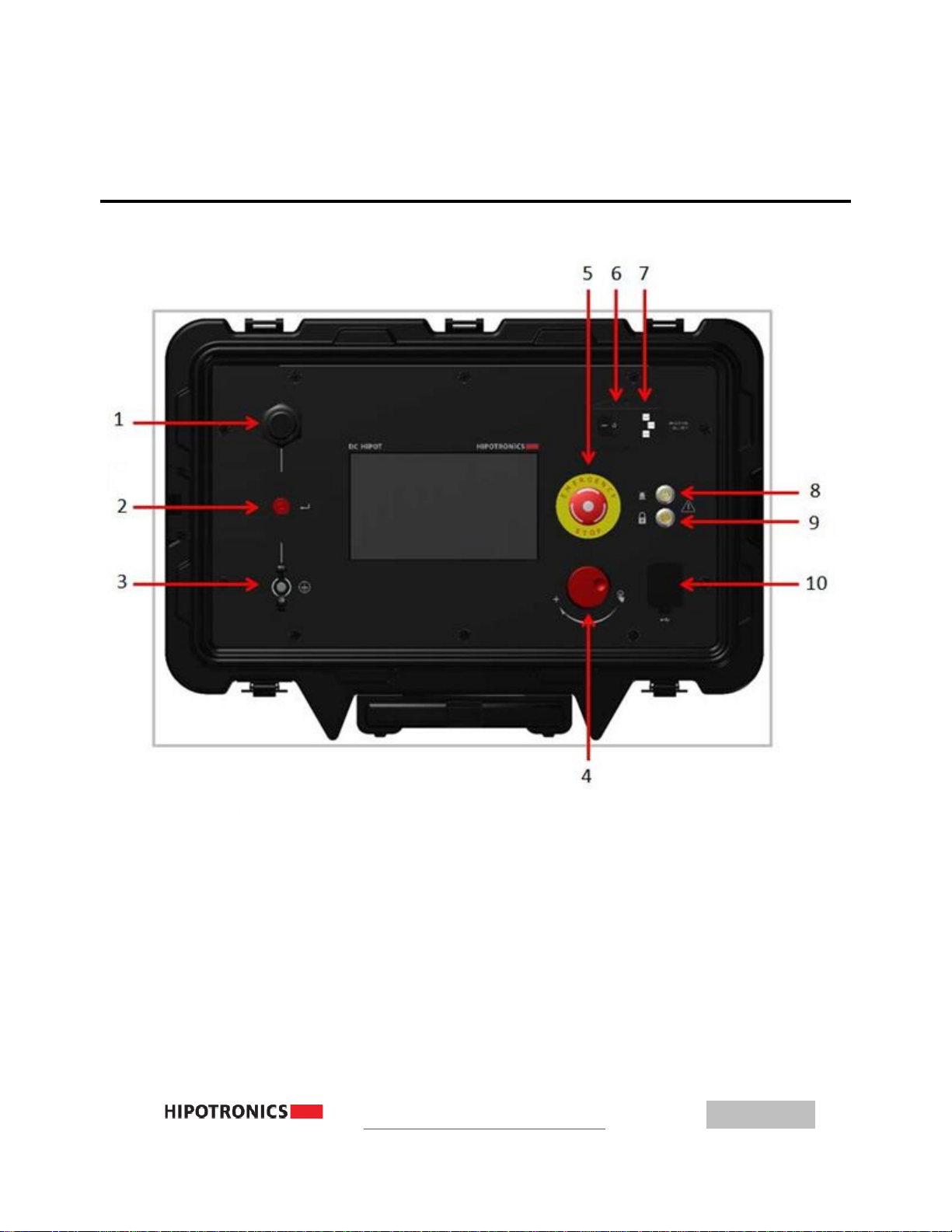
4840PL-HD Front Panel
4.0 Interface Points-of-Interest
1–High Voltage Output 6 –On/Off Power Switch
2–HV Return Input 7 –AC Power Input
3–Earth Ground Connection 8 –Warning Strobe Beacon Input
4–Rotary Knob Manual Control 9 –External Interlock Input
5–Emergency Stop 10 –USB input
Figure 1 800PL-DC Front Panel

10
840PL-HD Front Panel
4.1 Glossary of Front Panel Symbols
Symbol
Meaning
Symbol
Meaning
Safety Beacon Port
Protective Earth
Ground
Ground
Push-to-Click
Rotary Knob
Guard
Return
Interlock
USB
External Interlock
The External Interlock input allows for an external interlock or "deadman"
switch which will prevent High Voltage from turning on unless the interlock
switch is closed. If this feature is not used, the provided interlock plug must be
inserted into the provision in order for the unit to operate.
840PL-HD Front Panel
11
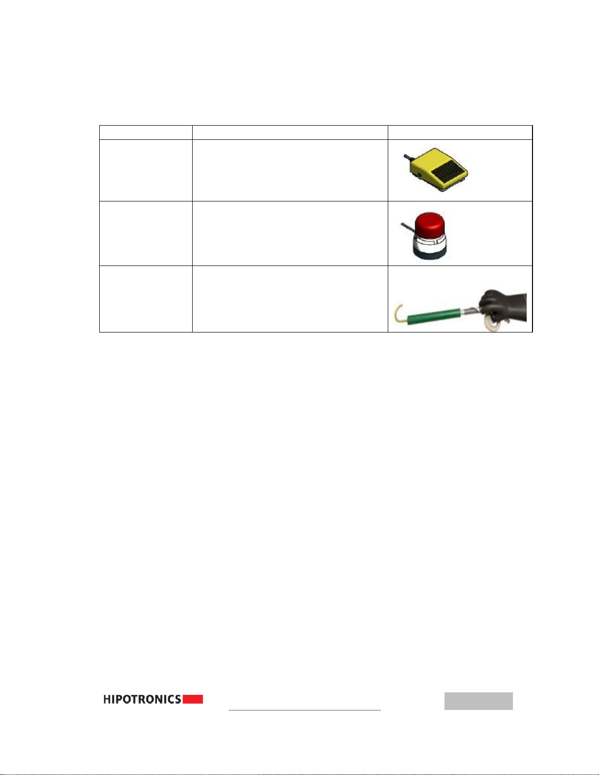
Accessories
The following accessories are available for the 800PL-DC
Part Number
Description
Image
HH-FS
Foot-Operated Interlock Switch
HH-SAFE
Safety Strobe Light with Magnetic
Base
HHDA13-280
Grounding Stick with 25ft braided
lead, rated to 120kV
12
Connection and Setup
5Connection and Setup
5.0 Ground Connections
First, make sure to connect a ground cable from the 840PL-HD ground stud to a nearby earth-ground point.
The ground stud for the 840PL-HD is located on the bottom left corner of the front panel(as indicated in the
previous section).
5.1 Testing Connections
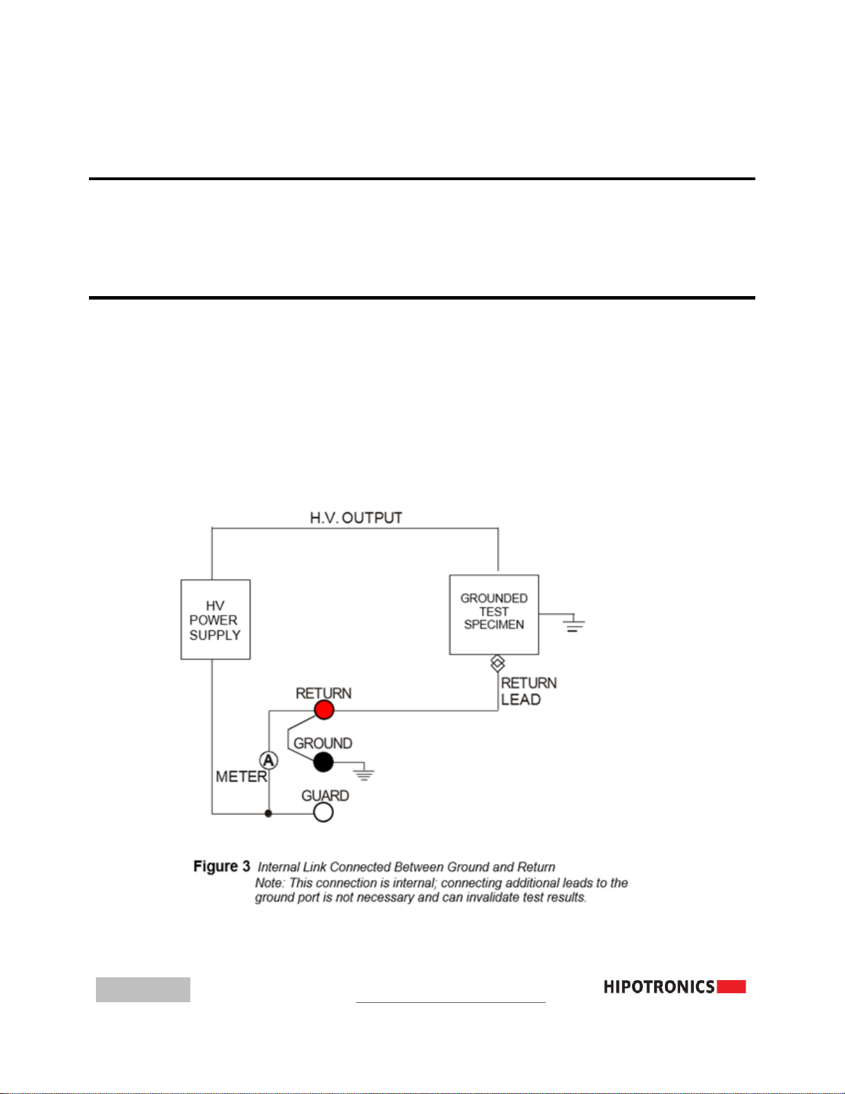
5.1.1 INTERNAL SWITCH BETWEEN GROUND AND RETURN (GST)
When GST is selected, all current is presented to the current meter. This mode
of operation should be used only when extremely sensitive measurements are
unnecessary or when a test specimen must be grounded. Note that no
connection to GUARD is necessary.

Connection and Setup
13
Single Phase Cable:
Grounded Multi-Conductor Cable (Individual Concentric Neutrals/Shields):

14
Connection and Setup
Grounded Multi-Conductor Cable (Single Conductive Neutral/Shield):
Connection and Setup
15
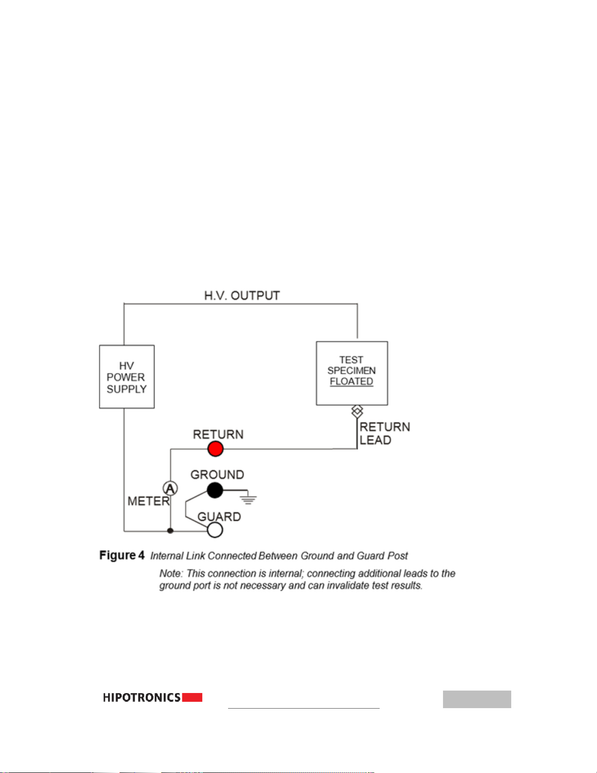
5.1.2 INTERNAL SWITCH BETWEEN GROUND AND GUARD (UST)
The sole function of this mode of operation is to separate the paths of leakage
currents. These leakage currents are leakage to ground and leakage across the test
specimen. The leakage currents to GROUND are bypassed around the current
meter, measuring only the specimen leakage current. The low side (RETURN)
connection of the specimen must be "floated" (isolated from GROUND). This
mode of operation should be used only when extremely sensitive measurements
are desired.
This is typically used for discrete components or when leakage to GROUND is to be
disregarded. For example, when testing a transformer for leakage (or resistance)
between the secondary and the primary, the guarded return mode allows leakage
to the core or frame to bypass the meter, thus reading only leakage between
the two coils.
It is not possible to test installed cables in this mode of operation, as the cable shields are always
grounded, making it impossible to see the leakage current.
16
Connection and Setup
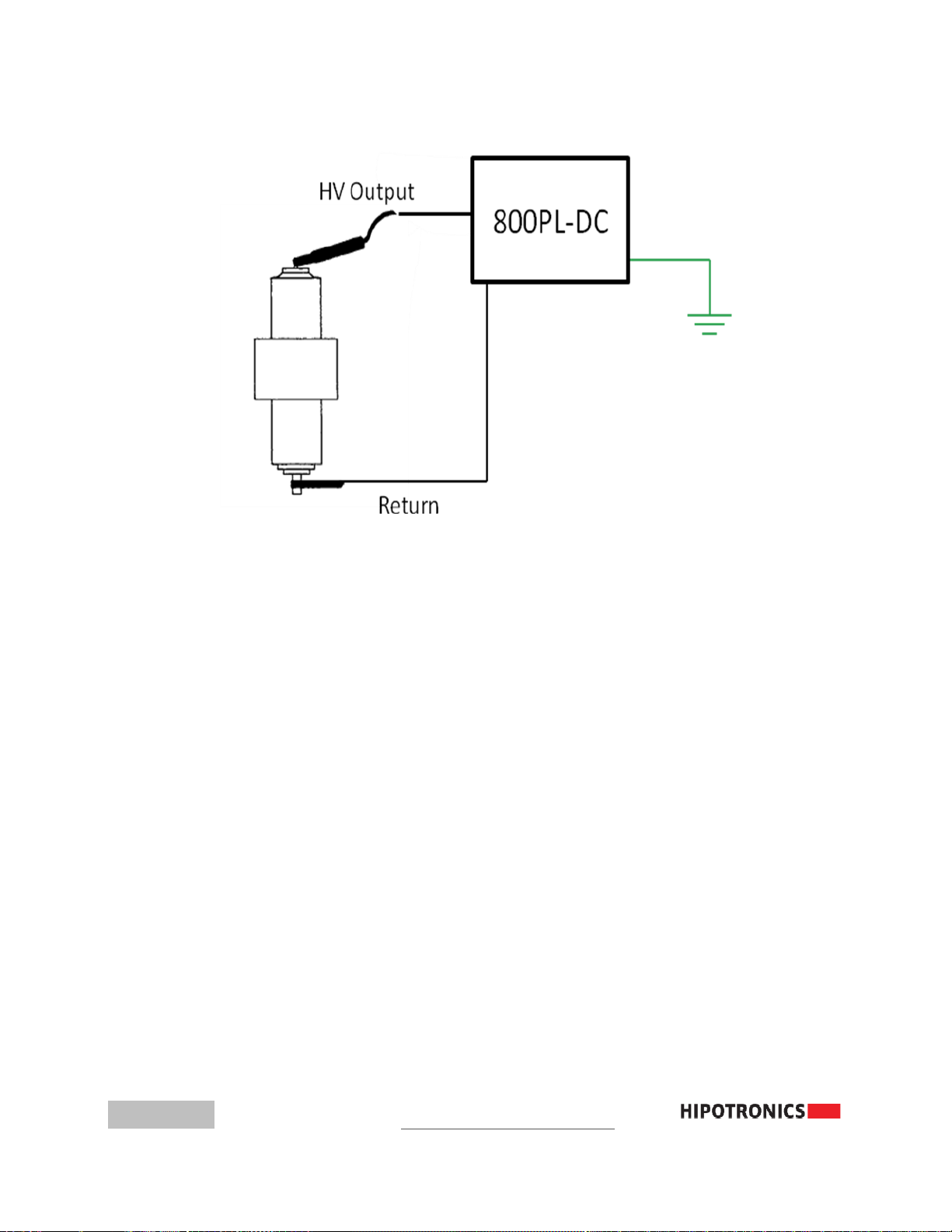
Vacuum Bottle
Special Safety Instructions
Follow these safety procedures upon completion of testing.
(a)
Turn Off Procedure
(b)
Warning!! Never press the HIGH VOLTAGE OFF pushbutton or turn
off the main power switch immediately upon completion of a high voltage test.
When stored energy is greater than 1 kilojoule, allow the energy to bleed
down until the voltmeter reading is zero.
In Automatic Mode:
Note: upon completion of test, step 1 is automatically done for you.
1. Allow the unit to automatically bleed off the voltage from the device under
test.
2. Completely discharge the cable through a resistive grounding (shorting) stick.
3. Attach a solid ground connection before touching the sample.
(c)
In Manual Mode, Especially When Completing Tests of Large Capacitive Loads
(e.g. power cables)
This manual suits for next models
1
Table of contents
Other HIPOTRONICS Test Equipment manuals


