HIRED-HAND System 2000 AUTO TEMP User manual

4801-1001 Rev 9/96
System 2000 AUTO TEMP
12 Stage Temperature Controller
Hired Hand, Inc.
1733 Co Rd 68
PO Box 99
Bremen, AL 35033

System 2000 AUTO TEMP Table of Contents
Table of Contents
1. Specifications _________________________________________________________1
2. Warnings ____________________________________________________________1
3. Description of Controller________________________________________________2
4. Offset/Differential Method ______________________________________________3
4.1. Offset: _________________________________________________________________3
4.2. Differential: _____________________________________________________________3
4.3. Examples _______________________________________________________________3
4.3.1. Heat Mode:__________________________________________________________________3
4.3.2. Cool Mode:__________________________________________________________________3
5. Programming the System _______________________________________________3
5.1. Day to Day Programming__________________________________________________4
5.1.1. The Display _________________________________________________________________4
5.1.2. Target Temp_________________________________________________________________4
5.1.3. Timer Runtime Percentage______________________________________________________4
5.1.4. Special Functions _____________________________________________________________4
5.2. The Program Features ____________________________________________________5
5.2.1. Flock Calculator______________________________________________________________5
5.2.2. Programming the Rooms _______________________________________________________6
5.2.3. Programming the Stages _______________________________________________________7
5.2.4. Setting the System Clock _______________________________________________________7
5.2.5. Saving and Restoring Levels ____________________________________________________7
5.2.6. Calibrating the Temperature Sensors______________________________________________8
5.2.7. Artificial Light _______________________________________________________________8
5.2.8. Feed Control_________________________________________________________________8
5.2.9. Viewing All Sensors___________________________________________________________8

System 2000 AUTO TEMP 1
System 2000 Auto Temp
1. Specifications
Model:
ACT-12 -- Staged on/off controller with 7 temperature inputs and 13 relay outputs
Electrical Ratings
Voltage Input -- 120 VAC (240VAC available) 50/60 Hz.
Power Consumption -- 20 VA Max.
Contact Ratings:
1/10 HP Inductive @ 120VAC
2 Amp @ 12VAC Resistive
Sensors:
Negative Temperature Coefficient Thermistor type. Maximum 1000 ft distance from sensor to controller.
Software calibration capability in controller.
Temperature Range:
-20.0F to 120.0F all targets settable in same range in 1F increments.
2. Limited Warranty
All products are warranted to be free from defects in material and workmanship for a
period of one year from the date of purchase if installed and used in strict accordance with
the installation instructions. Liability is limited to the sale price of any products proved to
be defective or, at manufacturers option, to the replacement of such products upon their
return. No products are to be returned to the manufacturer, until there is an inspection
and/or a return-goods authorization (RGA) number is issued.
All complaints should be directed first to the authorized distributor who sold the product.
If satisfaction is not obtained or the name of the distributor is not known, write the
manufacturer that appears below, directed to the attention of Customer Service Manager.
This limited warranty is expressly in lieu of any and all representations and warranties
expressed or implied, including any implied warranty of merchantability or fitness for a
particular purpose. The remedy set forth in this limited warranty shall be the exclusive
remedy available to any person. No person has authority to bind the manufacturer to any
representation or warranty other than this limited warranty. The manufacturer shall not be
liable for any consequential damages resulting from the use of our products or caused by
any defect, failure or malfunction of our products. (Some areas do not allow the exclusion
or limitation of incidental or consequential damages, so the above limitation or exclusion
may not apply to you.)
This warranty gives you specific legal rights and you may also have other rights that vary
from area to area.
Warrantor: Hired-Hand, Inc.
1733 Co. Rd. 68
PO Box 99
Bremen, AL 35033

System 2000 AUTO TEMP 2
3. Warnings
Warning!
When this system is used in a life support heating and ventilation system
where failure could result in loss or injury, the user should provide
adequate back-up, or accept the risk of such loss or injury.
Warning!
Electrical shock may occur if the Auto Temp is opened with power
connected to the unit. Before opening the enclosure, make sure that all
power sources to panel, and each stage, are disconnected.
Warning!
Wiring and connections must comply with all national and local electrical
codes. Installation by qualified electrician required.
4. Description of Controller
The Hired-Hand System 2000 Auto Temp Controller is a 12 relay, on/off, temperature/timer actuated,
staged controller. The controller also features 7 temperature inputs. The System 2000 offers several
unique and useful features. One such feature is that the Auto Temp can be programmed to control up to 6
separate rooms. Each room can have its own target, ramp, and timer. Any stage can be programmed to be
either heat or cool, and can be assigned to any room. Also, any of the 12 relay stages can be programmed
to use any single, or any averaged combination of temperature sensors to operate. The controller operates
off a single temperature set-point which is manipulated via the two buttons labeled Target Temp. The run-
time percentage of each room's timer is settable via the two buttons labeled Runtime Percent. The status of
the 12 stages is displayed on the face. A glance at the facepad will confirm whether a stage is on, whether
it is heat or cool, whether the stage is on a timer, and whether the function controlled by that stage is
actually running. All this information with push buttons and red lights -- the lights are on if a stage is on,
and are flashing if the stage is running. The stages are programmed using an offset/differential method.
This method is explained later in this manual.
It is not possible for both a heat stage and a cool stage to operate simultaneously by temperature in one
room. The reason for this is that the machine is always in either a heat mode, or a cool mode of operation.
If the system temperature (see Setup System section of Program Features) is less than the system target
temperature, then the machine is in a heat mode, whereas if the system temperature is equal to or greater
than the target temperature then the system is in a cool mode and cool stages may operate. Note, however
that any cool stage which is on the timer may operate regardless as to the mode of the system.

System 2000 AUTO TEMP 3
5. Offset/Differential Method
5.1. Offset:
The point above (cool) or below (heat) target temperature where the stage turns off.
5.2. Differential:
The difference in degrees between the temperature a stage comes on and the temperature the
stage goes off.
5.3. Examples
5.3.1. Heat Mode:
If the Target Temp is set at 80 degrees, Offset set at 4 degrees, and Differential set at 2
degrees, The System will engage Heat Mode when building temperature reaches 74
degrees and the curtains are closed.
Target Temp -Offset -Differential =Heat Mode on
80 -4-2=74
If the Target Temp is set at 80 degrees, Offset at 4 degrees and Differential set at 2
degrees, The System will disengage Heat Mode when building temperature reaches 76
degrees.
Target Temp -Offset =Heat Mode Off
80 -4=76
5.3.2. Cool Mode:
If the Target Temp is set at 80 degrees, Offset set at 5 degrees, and Differential set at 2
degrees, The System will engage the fans when building temperature reaches 87
degrees.
Target Temp +Offset +Differential =Cool Mode On
80 +5+2=87
If the Target Temp is set at 80 degrees, Offset set at 5 degrees, and Differential set at 2
degrees, The System will disengage the fans when building temperature reaches 85
degrees.
Target Temp +Offset =Cool Mode Off
80 +5=85
6. Programming the System
Programming the System 2000 Auto Temp Controller is like many other things--at first glance it looks
complicated, but if taken one step at a time it is really easy. In terms of programming the controller can be
broken down into two components. The first component is the group of functions which are present on the
facepad itself. These items are located on the facepad because they are the functions which are most often
used by the grower. The second level of programming is called the Program Features. These functions are
located by using the Select Features up and/or down arrows. These features aren't used as often as the
features on the facepad, but will be changed from time to time.

System 2000 AUTO TEMP 4
6.1. Day to Day Programming
6.1.1. The Display
The display on the Auto Temp controller has 2 parts; the 2 Liquid Crystal Displays
(LCD's) located across the top of the controller, and the stage status display which
occupies the left 2/3's of the pad. The LCD's normally display information on a room by
room basis. This information is the room number (room #), the current temperature (in
the right-hand display), the target temperature (tt:), and the target percentage (t%). If
the controller is programmed for more than one room, the LCD's will step room by room
with each room's information being present for about 4 seconds.
While the LCD's are displaying room information, the stage status display shows the
status of each stage. This display has 5 parts. Starting left to right is the Stage column.
This column has a light and a push-button switch, and indicates whether the stage is on.
If the light beside the number is on, then that stage is on; if the light is off, the stage is
off. Pushing the button beside the number for each stage will toggle the light on of off.
The next two columns are Heat and Cool, and indicate which mode the stage is
programmed for. The 4th column is the timer. Any cool stage can be put on the timer by
pushing the button to the right of the timer light. If the timer light is on for a stage, that
stage will run with the room timer. One last note concerning the timer lights; when a
light is flashing slowly, it means that the device that the stage controls is actually
running. The 5th and final column in the stage status display is the Function column,
and is a windowed pocket which can be used to describe the function of a particular
stage. A section of the System Program Guide can be cut out and installed in this slot.
6.1.2. Target Temp
The target temp is the temperature that the system is attempting to maintain. The default
display shows the current system target temperature under tt: If you wish to change the
target temperature in a given room, wait until that room number is displayed, and then
press and hold the Target Temp up or down arrow keys to raise or lower the target temp
respectively. Hold the button down until the wanted target temp is displayed. After a few
moments the system will start its default display sequence and begin to operate the
selected room using its new target temp.
6.1.3. Timer Runtime Percentage
The Runtime Percentage is the percentage of the Timer Period that any stage which
operates off the room timer will run. The timer in any given room cannot be on for less
than about 25 seconds. The default display shows the current runtime percentage under
t%. If you wish to change the runtime percentage in a given room, wait until that room
number is displayed, and then press and hold the Percent Run up or down arrow keys
until the new percentage is shown in the right hand display. After a few moments the
system will start its default display sequence and begin to operate the selected room
using its new runtime percentage.
6.1.4. Special Functions
6.1.4.1.Locking the Keypad
A means is provided for the operator to lock the face pad on the System 2000.
This is useful to prevent others from changing the system setup, as well as to
help prevent accidentally altering the state of the machine. The system is
locked by pressing the Change Setting up and down arrows simultaneously and
holding them until the word locked appears in the facepad. The system is

System 2000 AUTO TEMP 5
unlocked by repeating the same sequence until the word unlocked appears in
the display. Note that the controller operates normally in every way while the
keypad is locked but it will not respond to any keys.
6.1.4.2.Initializing the Controller
If at any time it appears necessary to return the controller to the program
settings when it arrived from the factory, you can follow this procedure to "re-
initialize" the controller. When this is done, ALL information such as stage
setup, Room setup, etc. must be re-entered. To re-initialize the controller:
Remove power from the controller, reapply power, then when the display reads
Please Wait... press the Select Down, Change Up, and Target Up arrow keys
until the word "Init" appears in the display. The system is now re-initialized.
6.2. The Program Features
Before programming the Auto Temp it is important
to understand the basic principles of the Program
Features. The controller is programmed using these
4 keys located at the bottom left of the facepad. The
two leftmost keys are the Select keys, while the two
on the right are the Change keys. The Select keys
are used to select a programming feature. This is
accomplished by pressing either the up or down
select feature key until the desired programming
feature is displayed. These program features are
arranged in a loop (you can move forward (up) or
backward (down) through the loop with the Select
keys). In moving backward, (down) through the loop you move from one basic program to the
next. To make program changes other than yes to run the program or no to skip it, you must
move forward (up) through the loop. Once selected, the change setting keys answer Yes or No to
increase or decrease a value. Program Features can be exited by either of two ways. The operator
can either press Target Temperature up, or allow the machine to time-out by not pressing any
keys for several moments. Note that the machine is not operational while in Program Features.
6.2.1. Flock Calculator
This feature was added for poultry farms to keep a running total of how many birds they
should have at any given point in a growout.
6.2.1.1.Set flock count
Use the Change setting up and/or down arrow keys to set the number of birds
that were delivered to you at the start of the growout.
6.2.1.2.Set Growout Day
Use the Change Setting up and/or down arrow keys to set the day of the
growout. For example: if it is one week and three days into the growout, set the
number to 10 (7 days + 3 days).
6.2.1.3.Set Mortality
To use the flock calculator, you need to enter the number of deceased birds each
day. Use the Change Setting up and/or down arrow keys to set the number you
Select
Feature
Change
Setting
YES
NO
PROGRAM FEATURES

System 2000 AUTO TEMP 6
have counted. When you have entered the right number, press the Select
Features up arrow key to move to the next screen.
6.2.1.4.Data View
This part of the program will show you the day of the growout, number of birds
your flock contained originally, average daily mortality, and number of birds
that remain in your flock on this day in the growout.
6.2.1.5.Reset Flock Info
Selecting yes with the Change Setting up arrow clears all settings you have
entered in the Flock information section. Because it clears all information, you
need to only do this at the beginning of each growout.
6.2.2. Programming the Rooms
The auto Temp can control up to 4 different rooms with each room having its own
sensors, ramp, target temperature, and timer. The rooms are programmed under the
Program Feature called Program Rooms. The items programmed under this heading are:
Number of rooms, which Sensor is in which room, Temperature Ramp for each room,
and the Timer Period for each room. Each of these is discussed below:
6.2.2.1.Number of Rooms
The first entry required is the number of rooms. Use the Change
Setting arrows to select a number from one to four.
6.2.2.2.Sensors for Display
The second entry required is the Sensors for Display which is
important in 2 different ways. First of all the sensors selected here are
used to generate the default temperature which is displayed by the
controller. The second and perhaps most important use of Sensors for
Display is the fact that this composite temperature as compared to the
Target Temperature determines whether the controller is in heat mode,
or cool mode for that particular room. (Remember that no heat stage
may run while a cool stage is running.) Use as many sensors as
possible in each room.
When programming Sensors For Display, the system prompts as
follows:
Pick sensors to display
Use stages 1-7 Room 1
When displaying this prompt, the controller "bubbles" the lights on
stages 1-7 and then displays 1 or more lights continuously. At this
point, the stage 1 light represents sensor 1, Stage 2 light is sensor 2,
and so on. If you wish to use an average of sensors 1,2, and 3 for this
particular room, simply push the buttons for stages 1, 2, and 3 until
those 3 are lighted. You will be prompted for sensors for Display for
each of the Rooms selected in "Number of Rooms".

System 2000 AUTO TEMP 7
6.2.2.3.Automatic Temperature Reduction or Ramping
The System 2000 Auto Temp Controller can easily be programmed to
automatically reduce temperature on a day to day basis. Each room can
selectively have its own ramp. All that is required from the operator is
to enter the number of days for the ramp and then an ending target
temperature. The system uses this information along with the current
system Target Temperature to calculate a new target temperature for
each day. Note that if at any time during a ramp period the
temperature in the house seems to be too high, or too low, all that must
be done is to change the current target temperature (with the Target
Temperature arrows) and the ramp will continue from that point.
6.2.2.4.Timer Period
The System 2000 Auto Temp controller has a built-in cool stage timer
for each room. This timer may be set for a period of from 1 to 15
minutes. The timer is most often used as a 10 minute timer. Any cool
stage may be set to operate on a time as well as temperature basis via
this timer.
6.2.3. Programming the Stages
The System 2000 Auto Temp controller is an integrated 12 stage controller with a built
in timer. Each of the 12 stages can be programmed to be either a heat or a cool stage.
What's more, any cool stage can be placed on a timer in addition to standard
temperature-based operation. Each stage may operate off any combination of 7 sensors.
Each stage is programmed for temperature utilizing an offset/differential method. (See
Offset and Differential earlier in this manual.) Each cool stage can be placed on the
system timer. This is a programmable timer which may have a period of from 1 to 15
minutes, and any percentage from 1 to 100 percent. The stages are programmed in the
Program Features section of the controller
6.2.4. Setting the System Clock
The system clock is a battery-backed up 24 hour clock (12 hour with a.m. and p.m.)
Several functions operate using this clock--these include artificial lighting, and feed
control. It should be necessary to set the clock only once except to accommodate
standard/daylight savings time. The System Clock is located in the Programming
Features.
While setting clock the controller will ask you for several bits of information. this
information is used in calculating Sunrise, and Sunset. Thus it is important to be as
accurate as possible in setting the clock. Information the clock needs to operate properly
includes: Year, Month, Day, Hour, Minute, Time Zone, and the Latitude and Longitude
of the building the controller will be operating. (Latitude and Longitude is entered in #
of Degrees, # of Minutes, and # of Seconds.) It is important to be as accurate as possible
to ensure accurate controller operation throughout the year. The time zone code may be
found on the chart at the back of this manual. Latitude and Longitude can be obtained
from a topographical map, or the geological survey office in your area.
6.2.5. Saving and Restoring Levels
The Auto Temp has a mechanism that allows you to save the setup of the machine once
it has been programmed for a particular crop, and setup a completely different program

System 2000 AUTO TEMP 8
for an alternating crop. Then when you return to the original crop you could simply
restore the level you had saved. This will reprogram the stages back to the original
settings. Note: Saving a level completely erases the level which was previously saved for
that number, so be sure before you save. The system has accommodations for two levels.
6.2.6. Calibrating the Temperature Sensors
In any Given installation it is usually necessary to calibrate at least one of the seven
sensors. With a program located in the Program Features the Auto Temp makes this an
easy task. All that is needed to calibrate sensors is a stable building with no fans or
heaters running, and a trusted thermometer. Use the thermometer to check temperature
at the sensor locations. Then use the Select feature arrow keys to find Calibrate Sensors.
Answer Yes and the controller will ask for new temperature for Sensor 1, use the change
setting arrows to enter the correct temperature, then answer in the same manner for
Sensor 2, and so on.
6.2.7. Artificial Light
The Auto Temp Controller has a way to control artificial lighting based on a 24 hour
time clock. There is a connection in the controller labeled "Artificial Light", in and out.
An external relay or contactor must be used to control the lighting as the relay in the
Auto Temp is not heavy enough. When programming this feature, the operator is
prompted for Number of Cycles (up to two), Time on and Time off. The operator can use
up to two different light cycles in every day.
6.2.8. Feed Control
This feature can be used for feeders, or any other device that needs to run on a timed
basis. Feed Control allows you to set up the device to operate up to Four times a day.
The controller will prompt you for number of cycles (up to two), then begin cycle time,
and end cycle time for each. When Feed Control is used, it will use Stage 11, and Stage
12 for operation.
6.2.9. Viewing All Sensors
It is possible to view all 7 sensors on 2 separate screens with the System 2000. To see
the temperatures sensed by the sensors, go into programming features, and continue
until you see a screen with S-1... S-2... and so on. This screen, and the next shows the
actual sensor readings. This allows you to detect a problem with your setup, or the
sensor itself. The temperatures shown will update every 4 seconds while they are being
displayed.
Recommended Wire Gauge for LOW VOLTAGE hookup.
Component HHI Wiring Part No. Recommended Wire
Sensor 1502-2427 18/2 Shielded Cable
Hall Effect Devices 1502-2427 18/2 Shielded Cable
PVR-H 1503-1508 18/3 Cable SJT
Table of contents
Popular Temperature Controllers manuals by other brands
TE Technology
TE Technology TC-36-25 RS232 instruction manual
Pike
Pike EZ-ZONE PM quick start guide

IFM Electronic
IFM Electronic efector 600 TN21 Series operating instructions

PCB Piezotronics
PCB Piezotronics IMI SENSORS TO642A31 Installation and operating manual
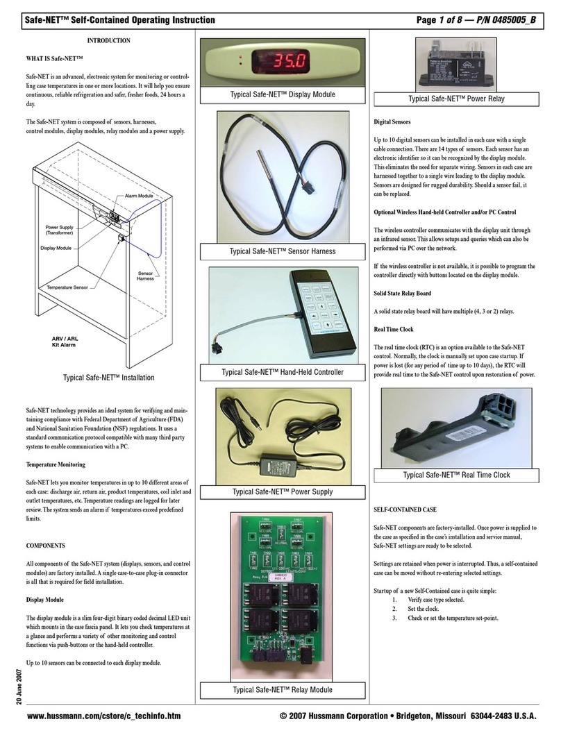
Hussmann
Hussmann Safe-NET operating instructions
Icon Electronics
Icon Electronics D3-TCT1 operating instructions
