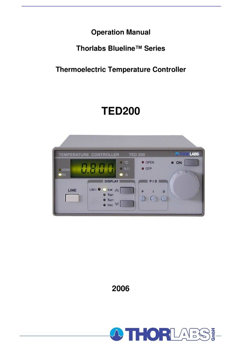
THORLABS TED350 User manual

Operation Manual
Thorlabs Instrumentation
Temperature Controller
TED350(-IEEE)
2007

Version: 2.14
Date: 07.02.2007
Copyright©2007, Thorlabs, Germany

Contents Page
1General description of the TED350 controller 1
1.1 Packing List 1
1.2 Safety 1
1.3 General functions 3
1.3.1 Protections for the TEC element 3
1.3.2 Description of operation 4
1.4 Technical data 5
1.5 Operating elements 8
1.5.1 Front panel 8
1.5.2 Back panel 9
1.6 Pre-settings 10
1.6.1 Setting the limit value of the TEC current 10
1.6.2 Setting the maximum allowed temperature 10
1.6.3 Setting the temperature window 10
1.7 Connecting components 11
1.7.1 Pin assignment of the output jack 11
1.7.2 Connecting a thermistor 12
1.7.3 Connecting a temperature sensor AD590 or AD592 13
1.7.4 Connecting a temperature sensor LM135 or LM335 13
1.7.5 Connecting an LM35 14
1.7.6 Connecting the Pt-100 (option) 15
1.7.7 Connecting a TEC element 15
1.7.8 Connecting the status indicator 17
1.7.9 Fine tuning of the temperature 18
2Operating the TED350 19
2.1 Manual operation 19
2.1.1 Selecting the sensor 19
2.1.2 Selecting the mode of operation 20
2.1.3 Selecting the displayed value 20
2.1.4 The output ANALOG OUT 21
2.1.5 Switching the output ON and OFF 21
2.1.6 Setting the PID shares 21
2.1.7 WIN OUT 21
2.1.8 Fix / Var selector 22
2.1.9 Wakeup setting DIP switch 22
2.2 Optimization of temperature control loops 24
2.2.1 Setup and function of temperature controllers 24

2.2.2 PID adjustment 26
3Communication with a control computer (TED350-IEEE) 28
3.1 IEEE488 interface (TED350-IEEE) 29
3.1.1 IEEE 488 Interface subsets 29
3.1.2 Setting up the interface 30
3.1.3 Connecting the PC 32
3.1.4 IEEE488 bus commands 33
3.2 Before Programming 35
3.2.1 Nomenclature 35
3.2.2 Program and response messages 35
3.2.3 Data format 36
3.3 Common commands and queries 37
3.3.1 Identification query 37
3.3.2 Reset 37
3.3.3 Self-test query 37
3.3.4 Set Operation-complete bit 37
3.3.5 Operation-complete query 38
3.3.6 Wait 38
3.3.7 Event-Status-Enable-Register (ESE) 38
3.3.8 Query Standard-Event-Status-Register (ESR) 38
3.3.9 Service-Request-Enable-Register (SRE) 39
3.3.10 Query Status-Byte-Register (STB) 39
3.4 System command group 40
3.4.1 Answer mode 40
3.4.2 Error-LED mode 40
3.4.3 Querying the error queue 41
3.4.4 Oversampling rate 41
3.5 Status command group 42
3.5.1 Query Device-Error-Condition-Register (DEC) 42
3.5.2 Query Device-Error-Event-Register (DEE) 42
3.5.3 Device-Error-Event-Enable-Register (EDE) 42
3.6 TED350 specific commands 43
3.6.1 Temperature sensor (SENS) 43
3.6.2 Operation mode (MODE) 43
3.6.3 Switching the TEC on and off (TEC) 44
3.6.4 Reading the TEC current hardware limit (LIMTP) 44
3.6.5 Reading the TEC temperature / resistance hardware limit (LIMTR)44
3.6.6 Temperature (only AD590 and LM35) (TEMP) 45
3.6.7 Resistance (only thermistor) (RESI) 46

3.6.8 TEC current (ITE) 47
3.6.9 Reading the temperature/resistance window (WIN) 48
3.6.10 Reading the TEC voltage (VTE) 48
3.7 Error messages of the TED350 49
3.7.1 General errors 49
3.7.2 TED350 operation error messages 51
3.8 Status reporting 53
3.8.1 Standard event status register (ESR) 55
3.8.2 Standard event status enable register (ESE) 55
3.8.3 Status byte register (STB) 56
3.8.4 Service request enable register (SRE) 56
3.8.5 Reading the STB by detecting SRQ 57
3.8.6 Reading the STB by *STB? command 57
3.8.7 Reading the STB by serial poll 57
3.8.8 Device error condition register (DEC) 58
3.8.9 Device error event register (DEE) 59
3.8.10 Device error event enable register (EDE) 59
3.9 Hints for setting up control programs 60
4Maintenance and Repair 63
4.1 General remarks 63
4.2 Cleaning 63
4.3 Selecting the line voltage 64
4.4 Exchanging the line fuse 64
4.5 Troubleshooting 66
5Service 68
5.1 Exchange of internal fuses 68
6Appendix 69
6.1 Warranty 69
6.2 Certifications and compliances 70
6.3 Thorlabs “End of Life” policy (WEEE) 71
6.3.1 Waste treatment on your own responsibility 72
6.3.2 Ecological background 72
6.4 List of acronyms 74
6.5 List of figures 75
6.6 List of tables 76
6.7 Addresses 76

We aim to develop and produce the best solution for your application in the
field of optical measurement technique. To help us to come up to your
expectations and develop our products permanently we need your ideas and
suggestions. Therefore, please let us know about possible criticism or ideas.
We and our international partners are looking forward to hearing from you.
Thorlabs
This part of the instruction manual contains specific information on how to operate
the temperature controller TED350. A general description is followed by explanations
of how to operate the unit manually. You will also find information about remote
control via the optional IEEE 488 computer interface.
Attention
This manual contains “WARNINGS” and “ATTENTION” label in this
form, to indicate dangers for persons or possible damage of equip-
ment.
Please read these advises carefully!
NOTE
This manual also contains “NOTES” and “HINTS” written in this form.

1.1 Packing List
TED350 / page 1
1 General description of the TED350 controller
1.1 Packing List
1 TED350 (-IEEE)
1 power cord, connector according to ordering country
1 operation manual
1 CD-ROM with Drivers (TED350-IEEE only)
1 connection cable CAB420-15
1.2 Safety
Attention
All statements regarding safety of operation and technical data in
this instruction manual will only apply when the unit is operated
correctly.
Before applying power to your TED350 system make sure that the
protective conductor of the 3 conductor mains power cord is cor-
rectly connected to the protective earth contact of the socket outlet!
Improper grounding can cause electric shock with damages to your
health or even death!
Also make sure that your line voltage agrees with the voltage indi-
cated by the switch setting on the back of the unit and that the right
fuse has been inserted!
The unit must only be operated with duly shielded connection cables.

1.2 Safety
TED350 / page 2
Only with written consent from Thorlabs may changes to single
components be carried out or components not supplied by Thorlabs
be used.
This precision device is only dispatchable if duly packed into the
complete original packaging including the plastic form parts. If
necessary, ask for a replacement package.
Attention
Mobile telephones, cellular phones or other radio transmitters are
not to be used within the range of three meters of this unit since the
electromagnetic field intensity may then exceed the maximum
allowed disturbance values according to EN 50 082-1.
Attention
The temperature controller TED350 must not be operated in explo-
sion endangered environments!

1.3 General functions
TED350 / page 3
1.3 General functions
1.3.1 Protections for the TEC element
To protect the connected TEC elements and the laser diodes the TED350 has the
following protective circuits:
•Limit of the TEC current in all operating modes
Protection against thermal destruction.
•Protection of the DUT by sensor failure
Protection against use of an incorrect temperature sensor / protection against
interruption of the temperature sensor connection.
•Contact protection of the TEC element (open circuit)
Protection against cable damage, bad contact or TEC element with too high
resistance.
•Separate over-temperature protection
Protection against thermal failure.
•Temperature-window protection of the laser diode
Operation in a specified temperature range. (Only in combination with a Thorlabs
LDC340)
•Mains filter
Protection against line transients or interference’s.
•Line failure protection
After turning on or in case of power failure or line damage the temperature control
must explicitly be switched on anew since it cannot be taken for granted that all
components of the measurement set-up are still working faultlessly.
•Key-operated power control switch
Protection against unauthorized or accidental use.

1.3 General functions
TED350 / page 4
1.3.2 Description of operation
The TED350 has an input for IC temperature sensors of the AD590/592 or
LM35/135/335 series as well as an input for thermistors. When thermistors are used
you can choose between two resistance ranges (maximum resistance of the
thermistor 20kΩor 200kΩ).
The TEC 350 with Pt-100 option uses the Pt-100 element instead of the LM35.
A missing sensor or the selection of an incorrect type is detected.
All settings are done with the manual operating elements or by the IEEE488-interface
(option) and a PC. Only the TEC current limit value must be set manually. No manual
settings are required during automatic tests using a PC.
The set values for temperature, thermistor resistance and TEC current (const. current
mode) are set with the 10-turn main dial knob.
The limit values for the TEC current, the temperature and the temperature window
are set with screw-driver potentiometers.
The P-, I- and D-share of the analog control loop are set with „thumb-nail“-
potentiometers.
The TEC element is always operated relative to ground. This is of considerable
advantage regarding the safety for the TEC element and the stability of the TEC
current.

1.4 Technical data
TED350 / page 5
1.4 Technical data
(All technical data are valid at 23 ± 5°C and 45 ±15% humidity)
Note: Technical data in remote control mode applies to TED350-IEEE only.
General Data
Line voltage 100 V / 115 V / 230 V (-10%, +15 %) (fixed)
Line frequency 50 ... 60 Hz
Max. power consumption 140 VA
Supply mains overvoltage Category II (Cat II)
Operating temperature 0 ... + 40 °C
Storing temperature - 40 °C ... + 70 °C
Relative Humidity Max. 80% up to 31°C, decreasing to 50% at 40 °C
Pollution Degree (indoor use only) 2
Operation altitude < 3000m
Warm up time for rated accuracy ≤10 min
Weight <7 kg
Dimensions (W x H x D) including operating elements 220 x 120 x 376 mm3
without operating elements 220 x 110 x 351 mm3
Current output TEC element
Control range - 5 A ... + 5 A
Maximum output power 40 W
Compliance voltage >8 V
Setting resolution (manual / remote control) 1 mA / 0.1 mA
Measurement resolution (manual / remote control) 1 mA / 0.1 mA
Accuracy ±20 mA
Noise and ripple, typ. <2 mA
Measurement resolution TEC voltage (manual / remote control) 1 mV / 0.1 mV
Measurement accuracy TEC voltage ±40 mV
TEC Current limit
Setting range 0 ... ≥5 A
Measurement resolution (manual / remote control) 1mA / 0.1 mA
Accuracy ±50 mA

1.4 Technical data
TED350 / page 6
Temperature sensors AD590, AD592, LM135, LM335, LM35
Control range (AD590, LM135, LM35) - 45 °C ... + 145 °C
Control range (AD592) - 25 °C ... + 105 °C
Control range (LM335) - 40 °C ... + 100 °C
Setting resolution (manual / remote control) 0.01 °C / 0.003 °C
Measurement resolution (manual / remote control) 0.01 °C / 0.001 °C
Accuracy ±0.1 °C
Temperature stability (24 hours) ≤0.001 °C
Thermistor (2 kΩ/ 20 kΩrange)
Measurement current 100µA / 10 µA
Control range 10 Ω... 19.99 kΩ/ 100 Ω... 199.9 kΩ
Setting resolution (manual control) 1 Ω/ 10 Ω
Setting resolution (remote control) 0.3 Ω/ 3 Ω
Measurement resolution (manual control) 1 Ω/ 10 Ω
Measurement resolution (remote control) 0.1 Ω/ 1 Ω
Accuracy ±5 Ω/ ±50 Ω
Temperature stability (24 hours) 1) ≤0.5 Ω/ ≤5 Ω
Pt-100 (Option)
Control range - 45 °C ... + 145 °C
Setting resolution (manual / remote control) 0.01 °C / 0.003°C
Measurement resolution (manual / remote control) 0.01 °C / 0.001°C
Accuracy ±0.3 °C
Temperature stability ≤0.005 °C
Temperature control input
Input resistance 10 kΩ
Control voltage -10 ... +10 V
Transmission coefficient IC-sensors 2 °C/V ±5%
Transmission coefficient thermistor (20 kΩ/ 200 kΩrange) 0.2 kΩ/V / 2 kΩ/V ±5%
1) Due to the nonlinear conversion from Ωto °C the stability in °C depends on the operating conditions
and the characteristics of the thermistor. E.g. for a typical thermistor at a set point of 10kΩ(25°C), a
0.5Ωstability translates into about 1mK temperature stability. At a set point of 5kΩ(38°C), the stability
is about 2mK.

1.4 Technical data
TED350 / page 7
Temperature control output
Load resistance >10kΩ
Transmission coefficient IC-sensors 10V / TWIN ±5%
Transmission coefficient thermistor 10V / RWIN ±5%
Temperature window protection
Setting range TWIN 0.5 °C ... 20 °C
Setting range RWIN (20 kΩ/ 200 kΩrange) 50 Ω... 2 kΩ/ 500 Ω... 20 kΩ
Computer Interface (TED350-IEEE)
Setting resolution 16 Bit
Measurement resolution 11 ... 18 Bit 1)
1) Configurable from 11 Bit + sign (sample rate 18/s) to 18 Bit + sign (sample rate 2/s), see chapter
3.4.4, “Oversampling rate” on page 41

1.5 Operating elements
TED350 / page 8
1.5 Operating elements
1.5.1 Front panel
Figure 1 Operating elements on front panel
F1 4 ½ digit LED display and 10 LED's for unit and status information
F2 Sensor selection field, AD590 / LM35 (Pt-100) / Thermistor high / Thermistor
low
F3 TEC output current ON / OFF switch
F4 Mains power control switch
F5 Modulation input and analog voltage output (BNC)
F6 Display selection field
F7 Operating mode selection: Const. current / const. temperature (resistance)
F8 PID-temperature control loop settings
F9 Main dial knob (10 turn)
I
I
F1 F2 F3
F4 F5 F6 F7 F8 F9

1.5 Operating elements
TED350 / page 9
1.5.2 Back panel
B1 B2 B3 B4
B5 B6 B7 B8 B9
Figure 2 Operating elements on rear panel
B1 Fan air outlet
B2 Temperature window output for LDC340
B3 IEEE488 interface jack
B4 Mains voltage selector
B5 Fix: Set values determined by potentiometers, Var: Adjustable by main dial
B6 Unit wakeup settings (DIP-switch)
B7 TEC output jack (15-pin D-SUB jack)
B8 DIP-switch for interface settings
B9 Mains jack with fuse holder

1.6 Pre-settings
TED350 / page 10
1.6 Pre-settings
To protect the TEC element and the other components of the setup the maximum
allowed TEC current, the maximum temperature as well as an operating temperature
window may be selected.
1.6.1 Setting the limit value of the TEC current
•Check the maximum allowed TEC current in the datasheet of your TEC
element.
•Select the display ITEC LIM.
•Change the limit value of the TEC current to the desired value with the
screwdriver-potentiometer besides the LED ITEC LIM.
1.6.2 Setting the maximum allowed temperature
To set the maximum allowed temperature (or the minimum allowed resistance):
•Check the type of temperature sensor in your setup.
•Select this sensor in the field marked “SENSOR“.
•Select the display TSET LIM.
•Change the limit value of the temperature (or resistance) to the desired value
with the screwdriver-potentiometer next to the LED TSET LIM.
1.6.3 Setting the temperature window
•Check the type of temperature sensor in your setup.
•Select this sensor in the field marked “SENSOR“.
•Select the display TWIN.
•Change the size of the window to the desired value with the screwdriver-
potentiometer next to the LED TWIN. The display shows a “plusminus“ – value,
so if you select i.e. 5.000°C the window will reach from 5°C below the set
value to 5°C above the set value.
•Activate this function with DIP switch 4 (Refer to chapter 2.1.9 on page 22)

1.7 Connecting components
TED350 / page 11
1.7 Connecting components
1.7.1 Pin assignment of the output jack
(15-pole female D-SUB, rear panel view)
Figure 3 Pinning of the output jack
Pin Connector
TEC element
5,6,7 TEC element (+)
13,14,15 TEC element (-), ground
2Voltage detector TEC element (+)
9Voltage detector TEC element (-)
Status indicator
1Status-LED (+)
8Status-LED (-), ground
Temperature sensor
3Thermistor (-), ground
4Thermistor (+)
10 AD590/592 (-), (Pt-100 -)
11 AD590/592 (+), (Pt-100 +)
12 Supply voltage for Thorlabs-mounts
8 7 6 5 4 3 2 1
15 14 13 12 11 10 9

1.7 Connecting components
TED350 / page 12
The TEC element and the temperature sensor must be connected to the output jack
at the rear of the TED350 according to the shown pin assignment with shielded
cables.
The shielding of the cable must be connected to ground (pin 13,14,15).
1.7.2 Connecting a thermistor
The thermistor is set up between pin 3 and pin 4. The polarity is unimportant if the
thermistor is floating. If one pin of the thermistor is grounded (for example in a laser
module), this pin has to be connected to pin 3.
Using a thermistor, all temperatures are shown in ohms, therefore you have to look
for the corresponding temperature in the datasheet of the thermistor.
Figure 4 Connecting a thermistor
When the actual temperature "TACT" is chosen for display the thermistor resistance is
shown. The pushbutton (F2, Figure 1) selects the resistance range of the thermistor.
In position "TH < 20 kΩ” the maximum thermistor range is 20 kΩand the measure-
ment current 100 µA. In position "TH < 200 kΩ” the maximum thermistor resistance is
200 kΩand the measurement current 10 µA.
The dependency of resistance on temperature and vice versa of an NTC-thermistor
is described by the formula:
val
val
TT
B
B
R
R
T
TB
RTeRTR val
+
=⇔∗=
−
)ln(*
*
)()(
0
0
0
)
11
(
00
(temperatures in Kelvin)

1.7 Connecting components
TED350 / page 13
with: R0: Thermistor nominal resistance at temperature T0
T
0: Nominal temperature (typ. 298.15 K = 25°C)
B
val: Energy constant
For R0and Bval refer to the data sheet of the thermistor.
Evaluate the thermistor resistance for the desired set temperature.
Select with the display selection keys (F2, Figure 1) the display value "TSET" to show
the set value and set the evaluated resistance value with the tuning knob (F9).
If the thermistor characteristic R(T) is given in the data sheet the desired resistance
can be read directly.
1.7.3 Connecting a temperature sensor AD590 or AD592
The IC-temperature sensor of the AD590 family is set up between pin 10 and pin 11.
These sensors translate the temperature into an equivalent current that can be
displayed and set directly in °C.
10
11
Figure 5 Connecting an AD590 or AD592
1.7.4 Connecting a temperature sensor LM135 or LM335
The IC-temperature sensor of the LM135 family is set up between pin 8, 10 and 11.
These sensors translate the temperature into an equivalent current that can be
displayed and set directly in °C.

1.7 Connecting components
TED350 / page 14
10
11
8
Figure 6 Connecting a LM135 or LM335
NOTE
When connecting a LM135 or LM335 you must select AD590 as
temperature sensor !
1.7.5 Connecting an LM35
The IC-temperature sensor of the LM35 series is set up between pin 10, pin 11 and
pin 8. These sensors will map the temperature into an equivalent voltage that can be
displayed and set directly in °C.
11
10
8
Figure 7 Connecting an LM35
LM35
out
-
+
This manual suits for next models
1
Table of contents
Other THORLABS Temperature Controllers manuals
THORLABS
THORLABS Blueline Series User manual

THORLABS
THORLABS TXP Series User manual

THORLABS
THORLABS MTD415T User manual

THORLABS
THORLABS TCLDM9 User manual

THORLABS
THORLABS ITC8000 User manual

THORLABS
THORLABS T-Cube TTC001 User manual

THORLABS
THORLABS TC300 User manual

THORLABS
THORLABS TC200 User manual

THORLABS
THORLABS TED8 Series User manual
THORLABS
THORLABS TED200C User manual