Salus SP120 User manual

Instruction Manual
S-Series Single Channel Controller
S-Series Single Channel Controller
Model No SP120
2
SP120 Manual Ver 005.qxd:Layout 1 6/1/11 09:00 Page 1

PRODUCT COMPLIANCE
This product complies with the essential requirements of the following EC Directives:
•Electro-Magnetic Compatibility Directive 2004/108/EC
•Low Voltage Directive 2006/95/EEC
•EC Marking directive 93/68/EEC
SAFETY INFORMATION
These instructions are applicable to the Salus Controls model stated on the front cover of this manual
only, and must not be used with any other make or model.
These instructions are intended to apply in the United Kingdom only, and should be followed along
with any other statutory obligations - if you are in any doubt, please contact the Salus Controls
technical helpline.
This accessory must be fitted by a Competent person, and installation must comply with the
guidance provided in the current editions of BS7671 (IEE Wiring Regulations) and Part ‘P’ of the
Building Regulations. Failure to comply with the requirements of these publications could lead to
prosecution.
Always isolate the AC Mains supply before opening
or removing the unit from the wall or wall box.
Please leave these instructions with the end user where they should be kept in a safe place for future
reference.
SP120 INSTRUCTION MANUAL2
SP120 Manual Ver 005.qxd:Layout 1 6/1/11 09:00 Page 2
INTRODUCTION
A heating controller is used to switch the heating
system in your home on and off as needed. It works by
controlling the heating boiler according to a series of
programmed settings that take effect at different times
of the day.
The SP120 from Salus Controls is a stylish and accurate
single channel programmable heating controller. Fitted
with a large, easy to read Liquid Crystal Display (LCD),
this controller has been specifically designed to be used
for volt free and 230V AC heating applications.
The use of the revolutionary Touch Ring technology makes for simple usage, and is coupled with
a unique, smart design and the ‘one touch’ operation makes the SP120 easy to operate.
FEATURES
• Touch Ring Technology
• Large LCD with white backlight
• Stylish Casing
• Radio Controlled Clock (RCC)
• Volt Free Contacts
• Manual Time and date Setting Option
• Advance +1Hr function (maximum 9 hours)
• Holiday Function
• Service Function
• Three On/Off Periods each day
• Built in Start-up Programmes
3SP120 INSTRUCTION MANUAL
SP120 Manual Ver 005.qxd:Layout 1 6/1/11 09:00 Page 3
INSTALLATION
Please read the important safety information at the start of this manual before you begin to install
the device. The ideal position to locate the SP120 programmable heating controller is about 1.5m
above floor level. It should be mounted in a location where the controller is easily accessible,
reasonably lit and free from extremes of temperature and draughts. Do not mount the controller on
an outside wall, above a radiator or in a location where it may be subjected to direct sunlight.
The SP120 should be mounted in a location where it will not come into contact with moisture or
condensation, as this can affect the Touch Ring operation.
To ensure trouble free reception for both the Radio Controlled Clock (RCC) and the Radio Frequency
(RF) signal, always ensure that the programmable controller is mounted away from any possible
sources of interference (such as radios, TV sets, computers, etc.), and is not mounted on or in close
proximity to large metal objects. Installing the SP120 in enclosed areas such as cellars and basements
is not recommended.
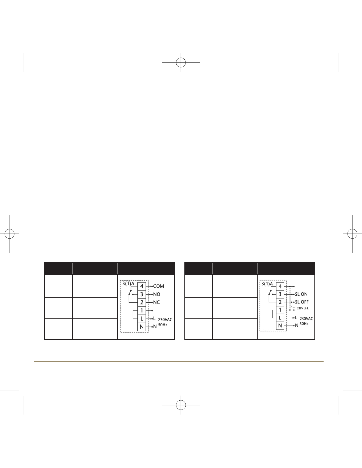
The electrical connections to the SP120 are made to the terminal strip within the controller itself.
Connection details are shown below - no Earth connection is required for the correct and safe
operation of the SP120.
230V AC Connections
Terminal Description Terminals
4 Linked to Live
3 (SL on) Switched Live On
2 (SL off) Switched Live Off
1 Live
L Mains Live
N Mains Neutral
Volt Free Connections
Terminal Description Terminals
4 (COM) Volt Free Common
3 (NO) Normally Open
2 (NC) Normally Closed
1 No connection
L Mains Live
N Mains Neutral
SP120 INSTRUCTION MANUAL4
SP120 Manual Ver 005.qxd:Layout 1 6/1/11 09:00 Page 4

After installing the controller in a suitable location, wiring connections can be made as shown above.
The following criteria apply to the installation:
• The incoming AC mains supply should be 230V AC and fused at 6 Amps.
• Optimum cable size for installation is 1.5 mm2; wiring colours should be in accordance
with the current requirements of the IEE Wiring Regulations.
• Cable entry should be made at the cable entry point
• All wiring connections should be securely made, and be firmly gripped beneath the terminal clamp.
Do not restore the mains supply to the system until all associated items are fully installed.
NOTE: All electrical installation work should be carried out by a suitably qualified Electrician or other
competent person. If you are not sure how to install this controller consult either with a qualified
Electrician, Heating Engineer or your boiler / heating system supplier for advice on how to continue.
Do not remove or refit the SP120 without the mains supply to the system being isolated.
AFTER INSTALLATION
After completing installation and powering up the SP120 for the first time the controller will behave
in the following way:
All the indicators on the display and the backlight will be turned on for a few seconds. The internal
firmware version will then be displayed for a few seconds, and the SP120 will then operate in Normal
mode (controller output OFF).
If the Reset Button is pressed, the SP120 will behave in the same way as described above, and any
previously saved user settings will be deleted and overwritten with the default settings, except when
the SP120 is in SERVICE mode.
5SP120 INSTRUCTION MANUAL
SP120 Manual Ver 005.qxd:Layout 1 6/1/11 09:00 Page 5

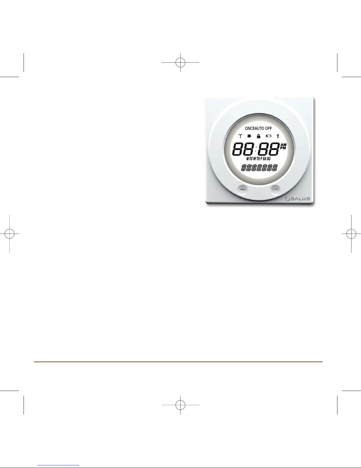
USER INTERFACE AND CONTROLS
The status and operation of the SP120 can be clearly seen on the
large backlit Liquid Crystal Display (LCD) - this display allows the
user to see at a glance the current status of the heating system.
The display consists of a combination of symbols and
alphanumeric displays. The top row displays status indicators, the
centre row is a time and day of the week indicator and the bottom
row is an alphanumeric display for menu and status messages.
The status indicator symbols and their meanings are shown in the
following table:
Indicator Description Function
Clock Display Displays the day and time
Alphanumeric Display Displays menu and other status messages
ON Mode indicator Indicates Continuously On
ONCE Mode indicator Indicates output is turned on for one period per
day, from PROGRAM 1 ON to PROGRAM 3 OFF
AUTO Program Mode indicator Indicates Auto ON or Auto OFF
programme is running
OFF Mode indicator Indicates Continuously Off
RCC indicator Indicates the status of the Radio Controlled Clock
Holiday indicator Indicates Holiday operation mode is selected
Touch Lock indicator Indicates Touch Lock is activated
Service indicator Indicates Service function is active
SP120 INSTRUCTION MANUAL6
SP120 Manual Ver 005.qxd:Layout 1 6/1/11 09:00 Page 6
USER CONTROL FUNCTION SUMMARY:
Key / Operation Functions
Touch Ring (move clockwise) Increases the selected setting and scrolls
down the menu selection
Touch Ring (move anti- clockwise) Decreases the selected setting and scrolls
up the menu selection
OK Key Enters Menu or confirms a menu selection
Arrow (Back) Key Single press goes back to the previous screen
or previous option selected. Press and hold for
2 seconds to return to NORMAL mode
Reset Button Resets the controller to default (original factory)
settings, except when in SERVICE mode.
Slide Switch Activates and deactivates the key lock function
(prevents accidental changes)
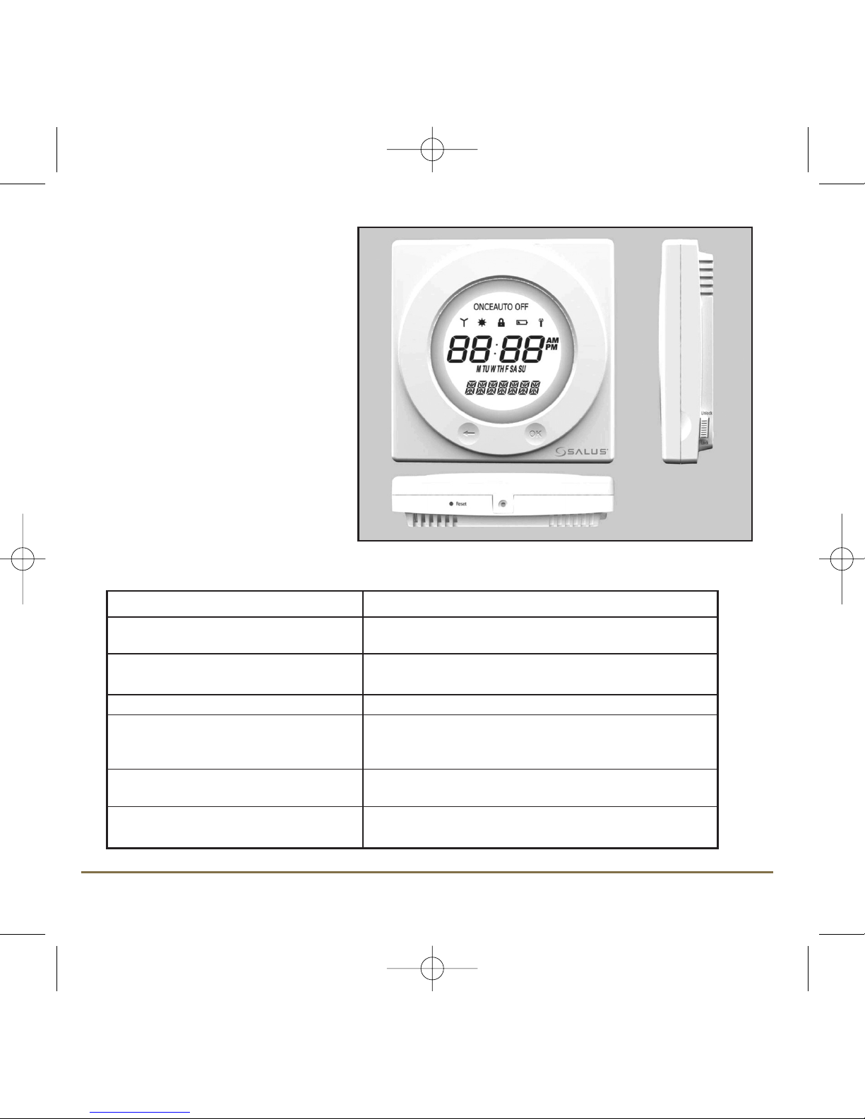
There are few user controls for the
SP120, making the controller very
easy to operate. The controls are a
Touch Ring (which surrounds the
user display), two touch sensitive
buttons, a reset button and a slide
operated switch mounted on the
side of the controller.
These controls are shown here,
along with a description of each of
their functions.
7SP120 INSTRUCTION MANUAL
SP120 Manual Ver 005.qxd:Layout 1 6/1/11 09:00 Page 7

OPERATION
The SP120 is configured and adjusted by the use of an
innovative and stylish Touch Ring, and two touch
sensitive buttons. The Touch Ring surrounds the
controller display, and is operated very easily by moving
your finger around the ring.
ACCESSING THE MENUS
The Arrow key is not active when
the SP120 is in NORMAL mode. To
access the Menu screens, press the
OK key twice and backlight is now
ON. The first menu displayed is the
BOOST menu. Use the Touch Ring
to scroll through the Menus, and
press the OK key to select the
menu you want to use:
You can scroll through the menus in either direction (forwards or backwards) depending on the
direction you move your finger around the Touch Ring. The menus are displayed in the order
shown in the picture above.
Pressing the Arrow key will return the SP120 to NORMAL mode. The controller will also return
to NORMAL mode after 10 seconds if no Key is pressed or if no movement is detected on the
Touch Ring.
SP120 INSTRUCTION MANUAL8
SP120 Manual Ver 005.qxd:Layout 1 6/1/11 09:00 Page 8

BOOST MENU
The BOOST menu allows the use of a temporary override mode which allows
the user to override the current programme settings and turn the heating
system on for a preset period. This mode is activated by selecting the BOOST
menu – this mode allows you to override the current programme settings up
to a maximum of 9 hours.
Scroll the setting by using the Touch Ring. Changing the setting will increase
the duration of the override by one hour, to a maximum duration of nine
hours. Increasing the setting beyond this level will roll the setting back to 0
and disable the temporary override.
PROGRAM MENU
The SP120 offers great versatility with its programming options, allowing the user to programme the
controller to operate on an individual, 5/2 or 7 day control cycle. The controller has a default set of
Programmes that have been designed to meet the needs of most users. If these default programmes
are not suitable for your particular situation, reprogramming the SP120 with your own settings is a
very straightforward operation.
To start programming the SP120, press the OK
key twice when in NORMAL mode, and scroll
using the Scroll Ring to select the PROGRAM
menu - press the OK key once more to start the
programming process.
Initially, the Weekdays will be selected and
flashing – you can scroll through all the various
options for day selection (Weekdays, Weekend,
7 days, or individual days) by using the Touch
Ring. As usual, pressing the OK key will select
the desired option.
9SP120 INSTRUCTION MANUAL
SP120 Manual Ver 005.qxd:Layout 1 6/1/11 09:00 Page 9

After correct selection of the day option, the
SP120 display will change to the next
programming screen. These screens allow you
to set the required time settings to provide
optimum control for your heating system.
The hour setting will be the first setting that
needs to be adjusted, and this will easily be seen
because the ‘hours’ section of the time will be
flashing. Using the Touch Ring, scroll up or
down to adjust the hour to the required setting
and then press the OK key to confirm. After
confirming this setting the ‘minutes’ section of
the time will then start to flash. Change this
setting using the Touch Ring in the same way
that you changed the hour setting, confirming
your setting with the OK key.
Following this sequence you will have set up
Programme 1 – the SP120 display will then
move on to Programme 2. Continue to add your
desired settings for each of the programmes
through to Programme 3 in the same way as
Programme 1 (hour and minutes). Note that the
Hour setting is changed in increments of 1 hour,
the Minutes setting is changed in increments of
10 minutes.
If you decide to enter settings for individual days rather than Weekdays or Weekends, the SP120
also offers a time saving COPY function that allows the user to copy settings from one day to another.
SP120 INSTRUCTION MANUAL10
SP120 Manual Ver 005.qxd:Layout 1 6/1/11 09:00 Page 10
Table of contents
Other Salus Temperature Controllers manuals


Popular Temperature Controllers manuals by other brands


SMC Networks
SMC Networks Thermo-con INR-244-639 Operation manual

eltherm
eltherm Ex-TC It Series operating instructions

Omron
Omron C200H-TV Series Operation manual

industrie technik
industrie technik CA1 instructions

KRAL
KRAL EET 32 operating instructions

dixell
dixell XR420C Installing and operating instructions