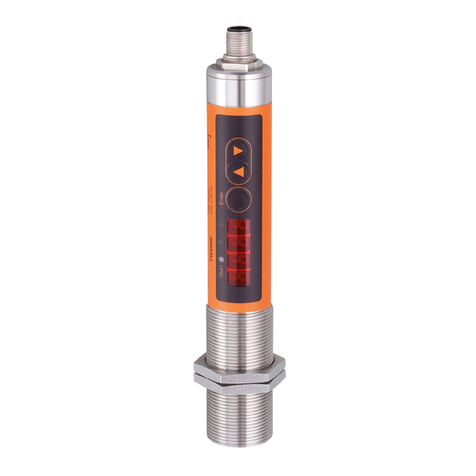
IFM Electronic efector 600 TN21 Series User manual

Operating instructions
Electronic temperature sensor
TN21xx
TN23xx
TN24xx
TN26xx
80235797 / 00 02 / 2016
UK

2
Contents
1 Preliminary note���������������������������������������������������������������������������������������������������3
1�1 Symbols used ������������������������������������������������������������������������������������������������3
2 Safety instructions �����������������������������������������������������������������������������������������������3
3 Functions and features ����������������������������������������������������������������������������������������4
4 Function���������������������������������������������������������������������������������������������������������������4
4�1 Switching function������������������������������������������������������������������������������������������4
4�2 Analogue function ������������������������������������������������������������������������������������������5
4�2�1 Current output���������������������������������������������������������������������������������������6
4�2�2 Voltage output���������������������������������������������������������������������������������������7
4�3 Display colour change �����������������������������������������������������������������������������������8
4�3�1 Parameter r1ou, r2ou, G1ou, G2ou������������������������������������������������������8
4�3�2 Parameter r-cF, G-cF����������������������������������������������������������������������������9
4�4 IO-Link �����������������������������������������������������������������������������������������������������������9
4�4�1 General information ������������������������������������������������������������������������������9
4�4�2 Device-specific information�������������������������������������������������������������������9
4�4�3 Parameter setting tools�������������������������������������������������������������������������9
5 Installation������������������������������������������������������������������������������������������������������������9
6 Electrical connection������������������������������������������������������������������������������������������10
7 Operating and display elements ������������������������������������������������������������������������ 11
8 Menu������������������������������������������������������������������������������������������������������������������12
8�1 Process value display (RUN) and menu structure���������������������������������������12
8�2 Explanation of the menu������������������������������������������������������������������������������13
9 Parameter setting ����������������������������������������������������������������������������������������������14
9�1 Parameter setting in general �����������������������������������������������������������������������15
9�1�1 Change between the menus���������������������������������������������������������������15
9�1�2 Change to the process value display (RUN mode) ����������������������������15
9�1�3 Locking / Unlocking ����������������������������������������������������������������������������16
9�1�4 Timeout�����������������������������������������������������������������������������������������������16
9�1�5 Configure colour change display �������������������������������������������������������16
9�1�6 Setting of the limit values for colour change���������������������������������������16
9�1�7 Read the min/max values �������������������������������������������������������������������17
9�1�8 Resetting all parameters to factory setting �����������������������������������������17

3
UK
1 Preliminary note
1.1 Symbols used
►Instructions
> Reaction, result
[…] Designation of pushbuttons, buttons or indications
→Cross-reference
Important note
Non-compliance can result in malfunction or interference�
Information
Supplementary note�
2 Safety instructions
• Please read this document prior to set-up of the unit� Ensure that the product is
suitable for your application without any restrictions�
• If the operating instructions or the technical data are not adhered to, personal
injury and/or damage to property can occur�
• Improper or non-intended use may lead to malfunctions of the unit or to unwan-
ted effects in your application� That is why installation, electrical connection,
set-up, operation and maintenance of the unit must only be carried out by
qualified personnel authorised by the machine operator�
• Check the compatibility of the product materials (→ Technical data) with the
media to be measured in all applications�
• The responsibility whether the measurement devices are suitable for the res-
pective application lies with the operator� The manufacturer assumes no liability
for consequences of misuse by the operator� Improper installation and use of
the devices result in a loss of the warranty claims�
10 Operation���������������������������������������������������������������������������������������������������������17
10�1 Reading of the set parameters ������������������������������������������������������������������17
10�2 Error indications / self-diagnostics�������������������������������������������������������������18
11 Technical data ��������������������������������������������������������������������������������������������������18
12 Factory setting �������������������������������������������������������������������������������������������������19

4
3 Functions and features
The unit monitors the system temperature in machinery and plants�
4 Function
• The unit displays the current system temperature�
• It features an IO-Link interface and is designed for full bidirectional communi-
cation�
• The unit generates 2 output signals according to the parameter setting:
OUT1/IO-Link:
- Switching signal, limit values for temperature
OUT2: 2 selection options
- Switching signal, limit values for temperature
- Analogue signal for temperature
4.1 Switching function
OUTx changes its switching status if it is above or below the set switching limits�
Hysteresis or window function can be selected�
Hysteresis function Window function
SPx
rPx
FHx
FLx
T = Temperature
SPx = set point
rPx = reset point
HY = hysteresis
Hno = hysteresis NO (normally open)
Hnc = hysteresis NC (normally closed)
T = Temperature
FHx = upper limit value
FLx = lower limit value
FE = window
Fno = window NO (normally open)
Fnc = window NC (normally closed)

5
UK
When the hysteresis function is set, the set point (SPx) is defined first and
then the reset point (rPx) which must be of a lower value� If only the set
point is changed, the reset point remains constant�
When set to the window function the upper limit value (FHx) and the lower
limit value (FLx) have a fixed hysteresis of 0�25 % of the final value of the
measuring range� This keeps the switching state of the output stable if the
temperature varies slightly�
4.2 Analogue function
• The unit converts the measured signal into a temperature-proportional ana-
logue signal� Depending on the parameter setting the output signal is at:
4���20 mA [ou2] = I
20���4 mA [ou2] = Ineg
0���10 V [ou2] = U
10���0 V [ou2] = Uneg
• The analogue signal can be scaled, that means the limits of the measuring
range for the lower output signal (ASP2 = analogue start point) and the upper
output signal (AEP2 = analogue end point) can be set�
Minimum distance between [ASP2] and [AEP2] = 5 K�

6
4.2.1 Current output
Maximum measuring range at [ou2] = I Measuring range scaled at [ou2] = I
MAW MEW
20.5
20
4
3.8
T [°C/°F]
I [mA]
I [mA]
T [°C/°F]MEWMAW AEP2ASP2
20.5
20
4
3.8
MAW = initial value of the measuring range
MEW = final value of the measuring range
ASP2 = analogue start point
AEP2 = analogue end point
Within the measuring range the output signal is between 4 and 20 mA�
If the temperature value (T) is outside the measuring range, the following output
signal is displayed:
[ou2] = I [ou2] = Ineg
T < MAW (ASP2) 3�8���4 mA 20�5���20 mA
T > MEW (AEP2) 20���20�5 mA 4���3�8 mA
In case of internal fault, the output signal behaves according to the parameter set
in [FOU2]:
[FOU2] = On [FOU2] = OFF
[ou2] = I 21 mA 3�5 mA
[ou2] = Ineg 3�5 mA 21 mA

7
UK
4.2.2 Voltage output
Maximum measuring range at [ou2] = U Measuring range scaled at [ou2] = U
MAW MEW
10.3
10
T [°C/°F]
U [V] U [V]
T [°C/°F]MEWMAW AEP2ASP2
10.3
10
MAW = initial value of the measuring range
MEW = final value of the measuring range
ASP2 = analogue start point
AEP2 = analogue end point
Within the measuring range the output signal is between 0 and 10 V�
If the temperature value (T) is outside the measuring range, the following output
signal is displayed:
[ou2] = U [ou2] = Uneg
T < MAW (ASP2) 0 V 10�3���10 V
T > MEW (AEP2) 10���10�3 V 0 V
In case of internal fault, the output signal behaves according to the parameter set
in [FOU2]:
[FOU2] = On [FOU2] = OFF
[ou2] = U 10�6 V 0 V
[ou2] = Uneg 0 V 10�6 V

8
4.3 Display colour change
The colour of the characters in the display can be set via the parameter [colr]�
With the parameters rED (red) and GrEn (green), the display is permanently set to
one colour� Via further parameters, the colour of the characters changes according
to the measured value:
OUT1 OUT2 OUT1 and OUT2 Colour change to���
Parameter r1ou r2ou r-cF red
G1ou G2ou G-cF green
4.3.1 Parameter r1ou, r2ou, G1ou, G2ou
SP1/
SP2
MAW MEW
Hysteresis function:
Colour change if measured value
is above the switch point
FL1/
FL2
FH1/
FH2
MAW MEW
Window function:
Colour change if measured value
is within the window range
MAW = initial value of the measuring range
MEW = final value of the measuring range

9
UK
4.3.2 Parameter r-cF, G-cF
cFL cFH
MAW MEW Colour change if the measured value
is within definable limits�
4.4 IO-Link
4.4.1 General information
This unit has an IO-Link communication interface which requires an IO-Link-capa-
ble module (IO-Link master) for operation�
The IO-Link interface enables direct access to the process and diagnostic data
and provides the possibility to set the parameters of the unit during operation�
In addition communication is possible via a point-to-point connection with a USB
adapter cable�
You will find more detailed information about IO-Link at www�ifm�com/gb/io-link�
4.4.2 Device-specific information
You will find the IODDs necessary for the configuration of the IO-Link unit and
detailed information about process data structure, diagnostic information and
parameter addresses at www�ifm�com/gb/io-link�
4.4.3 Parameter setting tools
You will find all necessary information about the required IO-Link hardware and
software at www�ifm�com/gb/io-link�
5 Installation
Before installing and removing the unit: Ensure that no medium can leak at
the process connection�

10
6 Electrical connection
The unit must be connected by a qualified electrician�
The national and international regulations for the installation of electrical
equipment must be adhered to�
Voltage supply to EN 50178, SELV, PELV�
►Disconnect power�
►Connect the unit as follows:
43
2 1
BK: black
BN: brown
BU: blue
WH: white
BN
WH
BK
BU
4
1
3
2OUT2
L+
L
OUT1
Colours to DIN EN 60947-5-2
Sample circuits:
2 x positive switching 2 x negative switching
L
L+
3 BU
4 BK
2 WH
1 BN
L
L+
3 BU
4 BK
2 WH
1 BN
1 x positive switching / 1 x analogue 1 x negative switching / 1 x analogue
L+
L
3 BU
4 BK
2 WH
1 BN
L+
L
3 BU
4 BK
2 WH
1 BN
Pin 1 L+
Pin 3 L-

11
UK
Pin 4
(OUT1)
• Switching signal: limit values for temperature
• IO-Link
Pin 2
(OUT2)
• Switching signal: limit values for temperature
• Analogue signal for temperature
7 Operating and display elements
4
2
1
6 5
3
1, 2, 3: Indicator LEDs
• LED 1 = switching status OUT1 (lights if output 1 is switched)
• LED 2 = temperature in the indicated unit of measurement
• LED 3 = switching status OUT2 (lights if output 2 is switched)
4: Alphanumeric display, 4 digits
• Display of current temperature in red or green colour�
• Display of the parameters and parameter values�
5: Buttons up [▲] and down [▼]
• Select parameters
• Change parameter values (hold button pressed)
• Change of the display unit in the normal operating mode (RUN mode)
• Locking / Unlocking (press buttons simultaneously > 10 seconds)
6: Button [
●
] = Enter
• Change from the RUN mode to the main menu
• Change to the setting mode
• Acknowledge the set parameter value

12
8 Menu
8.1 Process value display (RUN) and menu structure
RUN
°C °F
ou1 Hno Hnc Fno Fnc
Lo 0,0 °C
Hi 0,0 °C
FOU1 OFF On
FOU2 OFF On
P-n PnP nPn
uni °F°C
Hno Hnc Fno Fnc
ou2 I Ineg U Uneg
coF -10...10 °C
dr1 0,0...50 s
dS1 0,0...50 s
dr2 0,0...50 s
dS2 0,0...50 s
rES - - - -
cFH
diS
coLr rEd
r-cF G-cF
GrEn r1ou G1ou
r2ou G2ou
cFL
rd1 rd2 rd3 OFF
d1 d2 d3
1)
1)
EF
rP1
SP1
AEP2
ASP2
FH1
FL1
rP2
SP2 FH2
FL2
0,5...100 %
0,0...99,5 %
1) The parameters are only displayed when [coLr] = r-cF or G-cF�

13
UK
8.2 Explanation of the menu
SP1 / SP2 Set point (upper limit value) with hysteresis function
rP1 / rP2 Reset point (lower limit value) with hysteresis function
FH1 / FH2 Set point (upper limit value) with window function
FL1 / FL2 Set point (lower limit value) with window function
ASP2 Analogue start point
AEP2 Analogue end point
EF Extended functions� Opening of the lower menu level�
rES Restoring the factory settings
ou1 Output function OUT1 (switching output):
Hno = Hysteresis function normally open
Hnc = Hysteresis function normally closed
Fno = Window function normally open
Fnc = Window function normally closed
ou2 Output function OUT2 (switching output or analogue output):
Hno = Hysteresis function normally open
Hnc = Hysteresis function normally closed
Fno = Window function normally open
Fnc = Window function normally closed
I = current signal 4���20 mA
Ineg = current signal 20���4 mA
U = voltage signal 0���10 V
Uneg = voltage signal 10���0 V
dS1 / dS2 Switching delay on OUT1 / OUT2 in seconds
dr1 / dr2 Switch-off delay on OUT1 / OUT2 in seconds
FOU1 /
FOU2
Behavior of output OUT1 / OUT2 in case of an internal fault�
1� Switching output (FOU1 / FOU2):
On = Output 1 switches on in case of a fault�
OFF = Output 1 switches off in case of a fault�
2� Analogue output (FOU2 → 4.2.1):
On = The analog signal goes to the upper limit value�
OFF = The analog signal goes to the lower limit value�
uni Standard unit of measurement for temperature (°C or °F)
P-n Output logic: pnp / npn
Lo Minimum value of the temperature measured in the process since the last
reset or deletion of memory�

14
Hi Maximum value of the temperature measured in the process since the last
reset or deletion of memory�
coF Zero-point calibration� The internal measured value 0 is shifted by this value�
coLr Colour configuration of the display:
rEd = Process value always red�
GrEn = Process value always green�
r1ou = Process value red in case of switched output OUT1�
G1ou = Process value green in case of switched output OUT1�
r2ou = Process value red in case of switched output OUT2�
G2ou = Process value green in case of switched output OUT2�
r-cF = Display red if measured value between limit values cFL���cFH,
irrespective of the output function�
G-cF = Display green if measured value between limit values cFL���cFH,
irrespective of the output function�
cFH Upper limit value for colour change temperature�
cFL Lower limit value for colour change temperature�
diS Update rate and orientation of the display:
d1 = update of the measured values every 50 ms�
d2 = update of the measured values every 200 ms�
d3 = update of the measured values every 600 ms�
rd1, rd2, rd3 = display as for d1, d2, d3; rotated by 180°�
OFF = The measured value display is deactivated in the RUN mode�
The LEDs remain active even if the display is deactivated�
Error messages
are displayed even if the display is deactivated�
9 Parameter setting
Parameters can be set before installation and set-up of the unit or during operation�
If you change parameters during operation, this will influence the function
of the plant�
►Ensure that there will be no malfunctions in your plant�
During parameter setting the unit remains in the operating mode� It continues to
monitor with the existing parameter until the parameter setting has been completed�
The parameters can also be set via the IO-Link interface (→ 4.4)�

15
UK
9.1 Parameter setting in general
1� Change from the RUN mode to the main menu [●]
2� Select the requested parameter [▲] or [▼]
3� Change to the setting mode [●]
4� Modification of the parameter value [▲] or [▼] > 1 s
5� Acknowledge the set parameter value [●]
6� Return to the RUN mode → 9.1.2
Press [▲] + [▼] simultaneously to leave the setting mode without saving
the changed parameter�
If [C�Loc] is displayed when attempting to change a parameter value, a
change is made via a parameter setting software at the same time (tempo-
rary locking)�
If [S�Loc] is displayed, the sensor is permanently locked via software� This
locking can only be removed with a parameter setting software�
9.1.1 Change between the menus
1� Change from the RUN mode to the main menu [●]
2� Select parameter EF [▼]
3� Change to the submenu EF [●]
4� Select parameter CFG, MEM, DIS [▼]
5� Change to the submenu CFG, MEM, DIS [●]
6� Return to the next upper menu [▲] + [▼] simultaneously
9.1.2 Change to the process value display (RUN mode)
There are 3 possibilities:
I� Wait for 30 seconds (→ 9.1.4)�
II� Press [▲] until the RUN mode is reached.
III� Press [▲] + [▼] simultaneously until the RUN mode is reached.

16
9.1.3 Locking / Unlocking
The unit can be locked electronically to prevent unintentional settings�
On delivery: not locked�
Locking ►Make sure that the unit is in the normal operating mode�
► Press [▲] and [▼] simultaneously for 10 s until [Loc] is displayed.
During operation: [Loc] is briefly displayed if you try to change
parameter values�
Unlocking ►Make sure that the unit is in the normal operating mode�
► Press [▲] and [▼] simultaneously for 10 s until [uLoc] is displayed.
9.1.4 Timeout
If no button is pressed for 30 s during parameter setting, the unit returns to the
operating mode with unchanged values�
9.1.5 Configure colour change display
►Select [coLr] and define the colour of the process value display:
rEd, GrEn, r1ou, G1ou, r2ou, G2ou, r-cF, G-cF (→ 4.3)�
[coLr]
9.1.6 Setting of the limit values for colour change
►Select [cFH] and set the upper limit value�
►Select [cFL] and set the lower limit value�
[cFH] and [cFL] are only displayed if [coLr] = r-cF or G-cF�
[cFH] und [cFL] are irrespective of the default set points� The setting
range corresponds to the measuring range and its minimum limit is
[cFL] and its maximum limit is [cFH]�
[cFH]
[cFL]

17
UK
9.1.7 Read the min/max values
►Select [Hi] or [Lo] and read the value�
[Hi] = max� value, [Lo] = min� value�
Delete memory:
►Select [Hi�T] or [Lo�T]�
► Briefly press [●].
► Keep [▲] or [▼] pressed.
> [----] is displayed�
► Briefly press [●].
It makes sense to delete the memories as soon as the unit operates
under normal operating conditions for the first time�
[Hi]
[Lo]
9.1.8 Resetting all parameters to factory setting
►Select [rES]�
► Press [●].
► Press [▲] or [▼] and keep pressed until [----] is displayed.
► Briefly press [●].
It is recommended to take down your own settings in the table before
carrying out the function → 12 Factory setting�
[rES]
10 Operation
After power on, the unit is in the RUN mode (= normal operating mode)� It carries
out its measurement and evaluation functions and provides output signals accord-
ing to the set parameters�
10.1 Reading of the set parameters
► Briefly press [●].
► Click [▼] to select the parameter.
► Briefly press [●].
> The unit displays the corresponding parameter value for about 30 s� After that
the unit returns to the RUN mode�

18
10.2 Error indications / self-diagnostics
Diplay Warning message
[SC1] Excessive current at OUT1� LED1 for OUT1 flashing�
[SC2] Excessive current at OUT2� LED1 for OUT2 flashing�
[OL] Detection zone exceeded�
[UL] Below the detection zone�
[C�Loc] Setting pushbuttons locked, parameter change rejected�
Active IO-Link communication�
[S�Loc] Setting pushbuttons locked, parameter change rejected�
Unlock using parameter setting software�
Analogue signal in case of an error → 4.2�
11 Technical data
Technical data and scale drawing at www�ifm�com�

19
UK
12 Factory setting
Factory setting User setting
TN2xx5 TN2xx3
SP1 60 °C 140 °F
rP1 50 °C 122 °F
SP2 120 °C 248 °F
rP2 100 °C 212 °F
ASP2 -50 °C 0 °F
AEP2 150 °C 300 °F
uni °C °F
ou1 Hno
ou2 I
dS1 0
dr1 0
dS2 0
dr2 0
FOU1 OFF
FOU2 OFF
P-n PnP
coF 0
coLr rEd
diS d2
Further information at www�ifm�com
This manual suits for next models
3
Table of contents
Other IFM Electronic Temperature Controllers manuals
Popular Temperature Controllers manuals by other brands

alre
alre FTRFB-080 Series manual

KMC Controls
KMC Controls STE-6010 Application guide

Modine Manufacturing
Modine Manufacturing MCP15-542.0 installation instructions

domat
domat THERMASGARD RTF Series Operating Instructions, Mounting & Installation

OEG
OEG Como Operating and installation instructions

PCS
PCS TC50 Series user manual

AEG
AEG RTF-A Operation and installation

Oxford Instrucments
Oxford Instrucments E1000 user manual

dixell
dixell WING XW60VS Installation and operating instructions

Cisco
Cisco Meraki MT10 installation guide

Quantum Northwest
Quantum Northwest Turret 6/AP Product overview

Advantage
Advantage Sentra SK-G Series reference guide