HiRO 160 Q User manual
Version 1.01
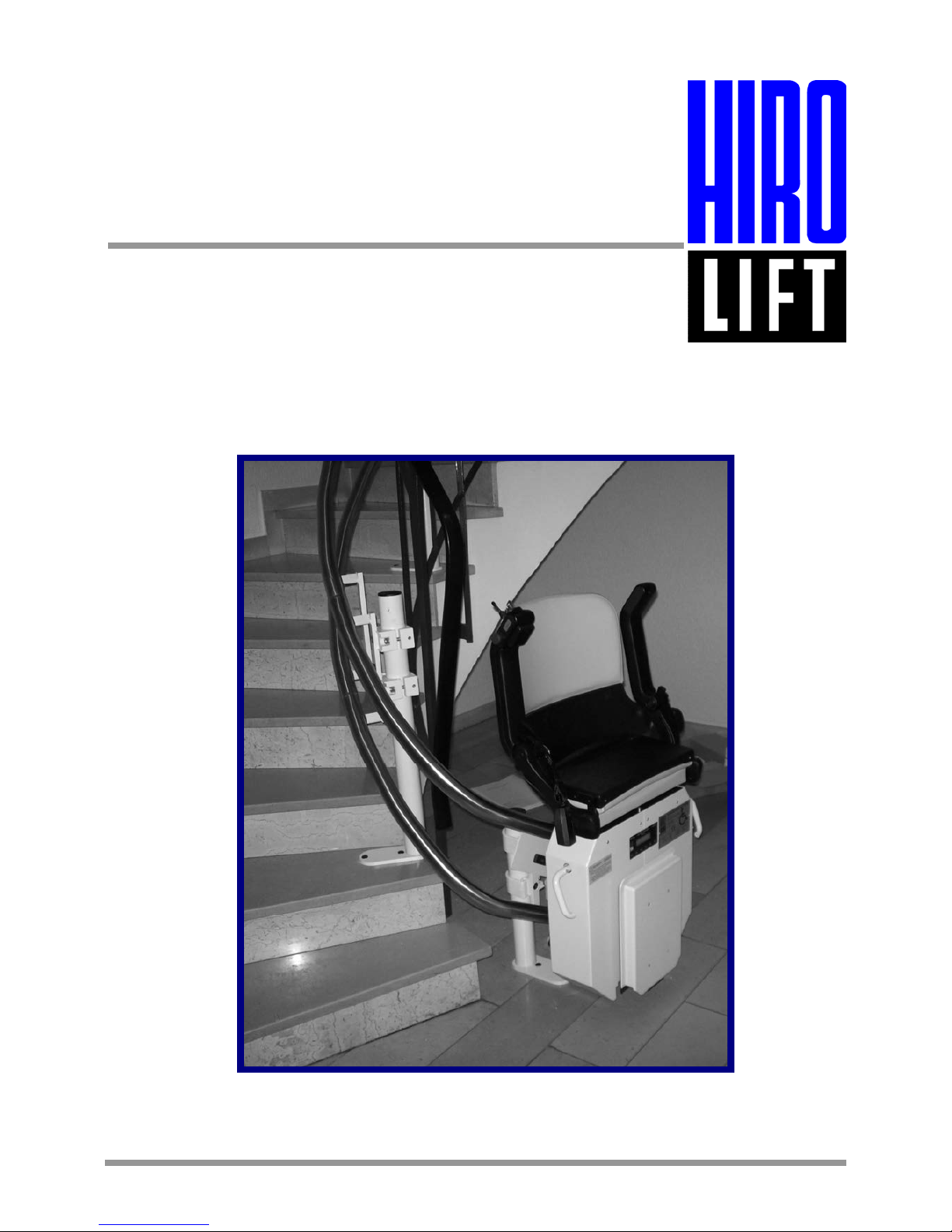
Installation instructions
for stair lift
HIRO 160 Q

1. Contents
2
Contents
1. Contents............................................................................................................................. Page 2
2. Key to symbols.................................................................................................................. Page 3
3. Assembly and installation procedure HIRO 160 Q.......................................................... Page 4
3.1 Tools ............................................................................................................................ Page 4
3.2 Preparations for work.................................................................................................... Page 5
3.3. Installation of guide rails ............................................................................................... Page 7
3.4 Installation of drive unit ............................................................................................... Page 12
3.5 Installation of chair...................................................................................................... Page 18
3.6 Installation of upper/lower stops ................................................................................. Page 20
3.7 Setting and testing the safety switches ....................................................................... Page 24
Please keep these instructions for further reference!

2. Key to symbols
3
Key to symbols
Caution! Risk of personal injury!
Attention! Risk of material damage!
Note
HIRO LIFT Hillenkötter + Ronsieck GmbH
Tel. +
49
/
521/
9
65
52- 0 Fax +
49
/
521/
9
65
52-
40 Meller Straße 6
Service +
49
/
521/
9
65
52-39 D 33613 Bielefeld
Email: info@hiro.de
.
Internet: www.hiro.de
Germany

3. Assembly and installation procedure HIRO 160 Q
4
3.1 Tools
The following tools are required for assembling and
installing a HIRO 160 Q stair lift:
•Percussion drill
•Percussion drill bits 6 - 14 mm
•Power drill
•Set of drill bits and taps for metric thread sizes
M4 - M12
•Power screwdriver
•Angle grinder
•Vacuum cleaner
•Set of socket spanners
•Set of open-ended/ring spanners
•Torx spanner T40
•Set of screwdrivers
•Electric power tool
•2 x chain hoist 250 kg
•Set of metric Allen keys
•Hydraulic jack
•Spirit level
•Tape measure

3. Assembly and installation procedure HIRO 160 Q
5
3.2 Preparations for work
The lift unit is supplied in the following packages:
1. Drive unit
2. Seat
3. Cover panels
4. Guide rail beams
5. Production parts list, lift unit drawing with list of
supports and fixing materials for the stops
6. Guide rail supports
7. Fixing brackets and screws for anchoring guide
rails and supports
8. Wall mount for charger unit
9. Electrical accessories kit with charger unit,
charging cable, charging bars, fixing materials,
magnets and bolts and screws
10. Lift unit drawing and documentation
11. Circuit diagram, list of parameters and
operating instructions for the control
12. Instructions and acceptance inspection
documentation
3. Assembly and installation procedure HIRO 160 Q
6
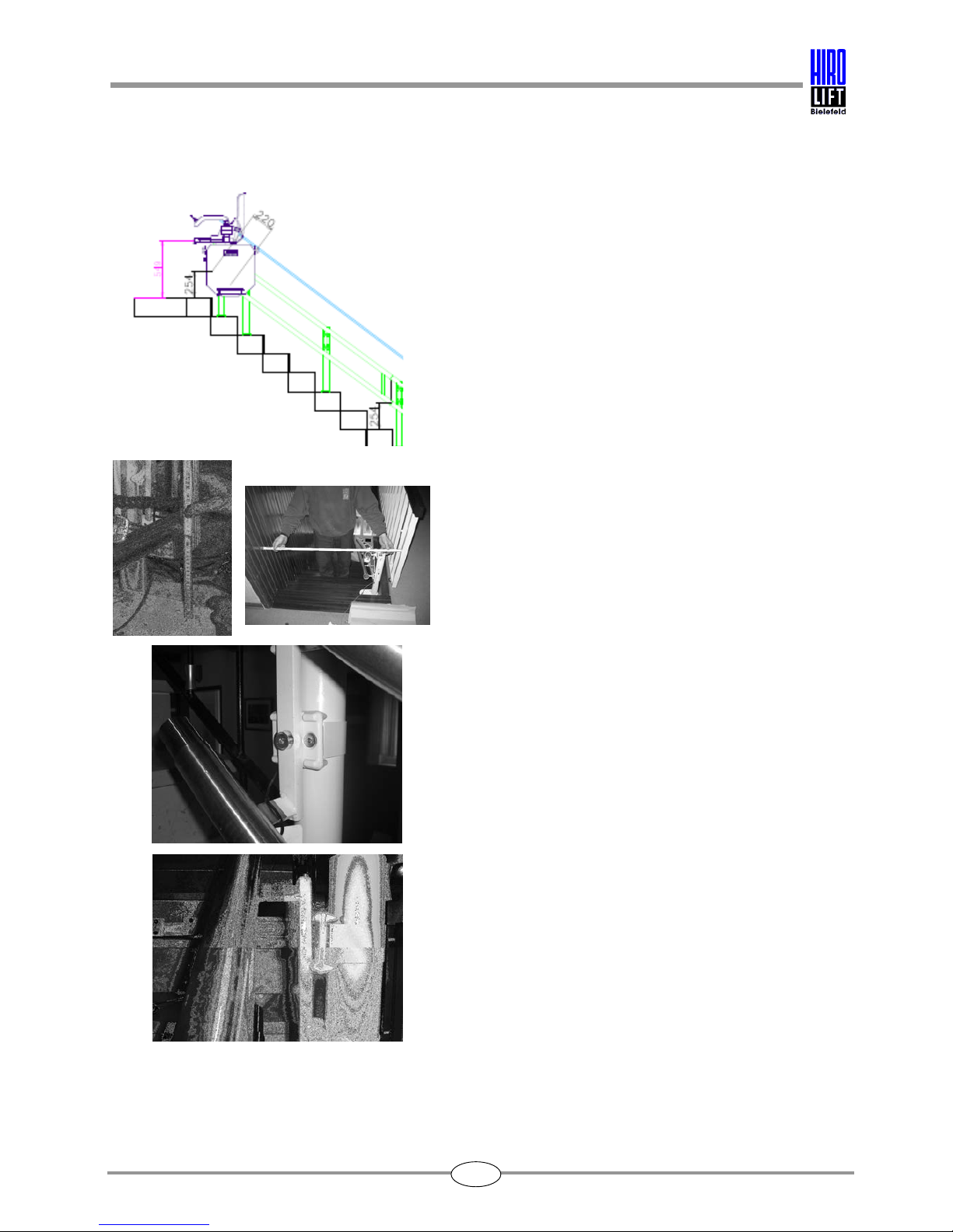
Before starting installation work, please check
whether the dimensions given in the lift unit drawing
agree with the actual dimensions on the installation
site.
Check against the lift unit drawing and the
production parts list to ensure that the lift unit
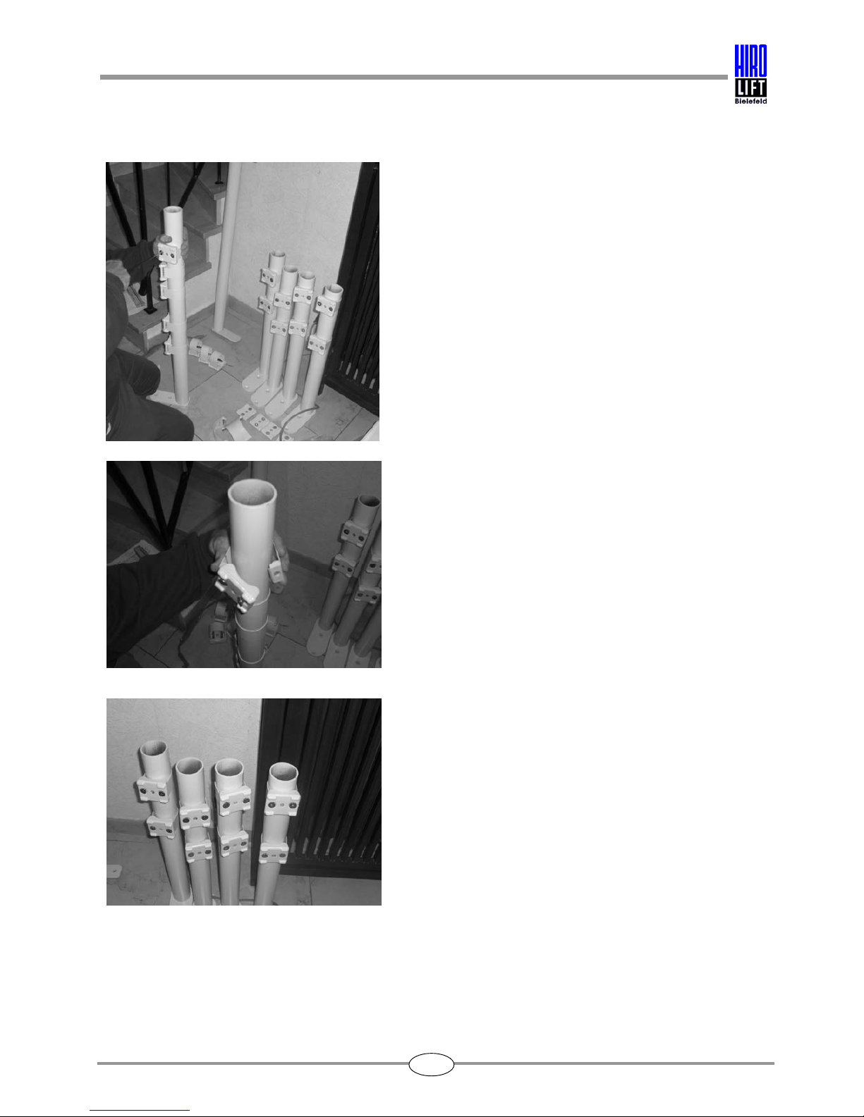
delivered is complete.
Arrange the guide rail supports according to length
and position.
Please refer to the list of supports to see which
support length is required in each case. The
position of the supports is shown in the lift unit
drawing.
All the dimensions relevant for the installation work
are shown in red on the lift unit drawing.
All dimensions on the lift unit drawing refer to the
centre of the guide rail tube.
The guide rail supports are shown as S1/S... in the
lift unit drawing and are indicated in the parts list
with their various lengths.
Take the fixing brackets out of the enclosed
accessories kit and take out the accompanying
screws for assembling the supports.
Place the guide rail supports, guide rail brackets,
clips and fixing screws on the staircase treads
specified in the lift unit drawing.

3. Assembly and installation procedure HIRO 160 Q
7
3.3 Installation of guide rails
In lift units where the guide rails are fixed to the
wall only, be sure to use through bolts or wall
anchors.
Where guide rails are fixed to the wall, the fixing
points are shown as W1 - W... on the lift unit
drawing.
If the guide rails are to be fixed to concrete, only
approved adhesive anchors or stud bolts must be
used.
When fixing the supports, they must be supported
with a bracket attached to the nearest wall
wherever possible.
The lift unit drawing specifies the distances
between the guide rail and the staircase tread.
Lay the lower end of the guide rail track on the
floor. The lower edge of the guide rail track is
specified in the lift unit drawing from the outer
edge of the staircase tread (zero point).
For lifts with a horizontal travel path, the height
dimension specified is that of the guide rail track.
Adjust the guide rail track with the supports loosely
attached or using a hydraulic jack.
Particular attention must be paid to ensure that the
guide rail track and the supports are properly
anchored.

3. Assembly and installation procedure HIRO 160 Q
8
Note!
Before installing the guide rails, the lower guide rail
cap must first be attached.
For lift units with guide rail supports in the stairwell,
the supports must be fitted first as shown in the lift
unit drawing.
The dimensions for each of the supports are given
in the lift unit drawing.
All dimensions refer to the centre of the tubular
supports.
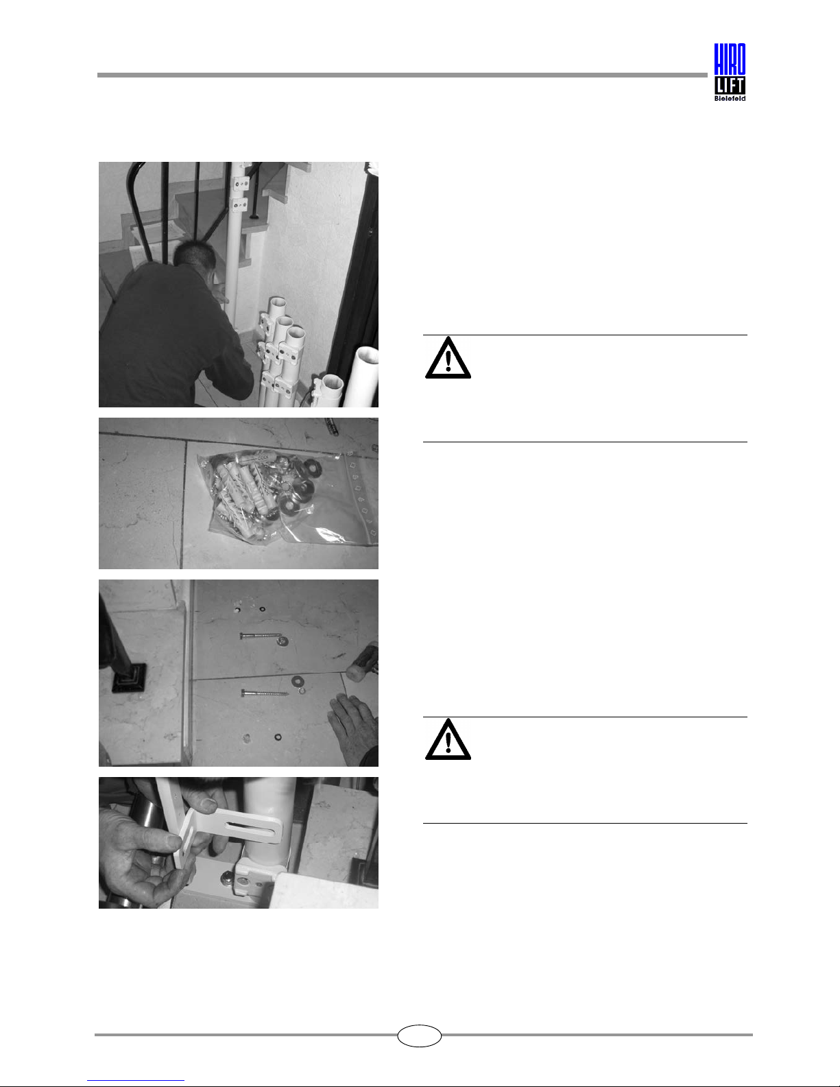
Mark the positions of the supports.
Place the supports on the pencilled in positions
and mark the position of the screw holes.
3. Assembly and installation procedure HIRO 160 Q
9
The size of drill bit to be used depends upon the
fixing materials contained in the enclosed
accessories kit and shown in the list enclosed with
the accessories.
Attention!
Before drilling, ensure that there are no cables or
underfloor heating present in the area concerned.
Different types of fixings are possible depending
on the subsurface and the floor covering.
Attention!
If the subsurface is loose, then the supports must
be fixed to concrete.

3. Assembly and installation procedure HIRO 160 Q
10
When fixing the supports, ensure that the supports
are correctly aligned both horizontally and
vertically.
If it is possible to brace the supports to the wall or
a similar surface, then the supports must also be
fixed by an additional means.
Refer to the drawing for the zero point (guide rail
starting point) and mark this point on the floor.
Align the guide rail on the zero point and install the
first guide rail beam as described above.

3. Assembly and installation procedure HIRO 160 Q
11
Align the guide rails in all directions using the spirit
level.
The lift unit drawing shows the height dimensions
at each join position between the guide rail beams.
Compare the clearance dimensions and the height
dimensions with the actual dimensions at the
installation site, and if necessary, adjust the guide
rail track.
To lay the charging cables, use a coiled cable or
the cable supplied.
After installing the first guide rail beam,
the charging cable must be laid inside the upper
guide rail tube.

3. Assembly and installation procedure HIRO 160 Q
12
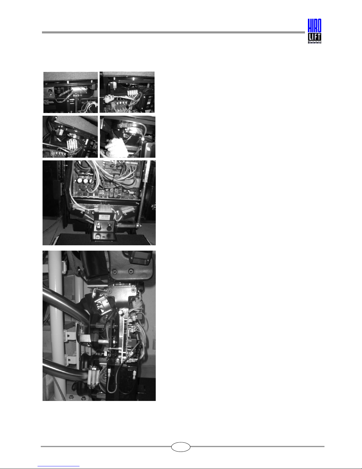
3.4 Installation of drive unit
At the lift stops, a ready-drilled hole is provided in
the upper guide rail tube near the guide rail fixing
plate for the purpose of laying the charging cable.
Secure the cable to the guide rail fixing plate.
Carry out the following steps to install the drive
unit:
Remove the packaging.
To allow the drive unit to be set down, a transport
frame is attached underneath it.
Install the footrest contact tray.

3. Assembly and installation procedure HIRO 160 Q
13
To suspend the drive unit in the guide rail, the
transport frame must be removed as shown in the
picture.
Switch the main switch to ON and insert the
emergency operation key into the appropriate key
switch.
Check the direction of rotation of the rollers by
turning the key switch.
Before suspending the drive unit, adjust the set of
rollers to the same angle of incline as that of the
guide rail track.
Lift the drive unit together with the set of rollers
onto the ends of the guide rail track.

3. Assembly and installation procedure HIRO 160 Q
14
By turning the key switch to the DOWN direction of
emergency operation, you can insert the drive unit
into the guide rail track.
Attention!
Ensure that the drive unit and the rollers are not
tilted.
Use the emergency operation facility to move the
drive unit into the lowest position and switch the
main switch to OFF.

3. Assembly and installation procedure HIRO 160 Q
15
The remaining guide rail beams are identified by
consecutive numbers.
The job number and the guide rail beam number
are shown on each guide rail beam.
Before inserting the guide rail beam, the charging
cable must first be laid in the guide rail tube.
Take care not to damage the charging cable when
fitting the guide rail beams together.
Grease both the guide rail ends and sleeves
before fitting the guide rail beams together.
If necessary, pull the guide rails together carefully
with a chain hoist.
3. Assembly and installation procedure HIRO 160 Q
16
The ends of the guide rails must be fitted together
without leaving any gap between them.
If necessary, maintain the tension between the
guide rails using a chain hoist or a screw clamp.
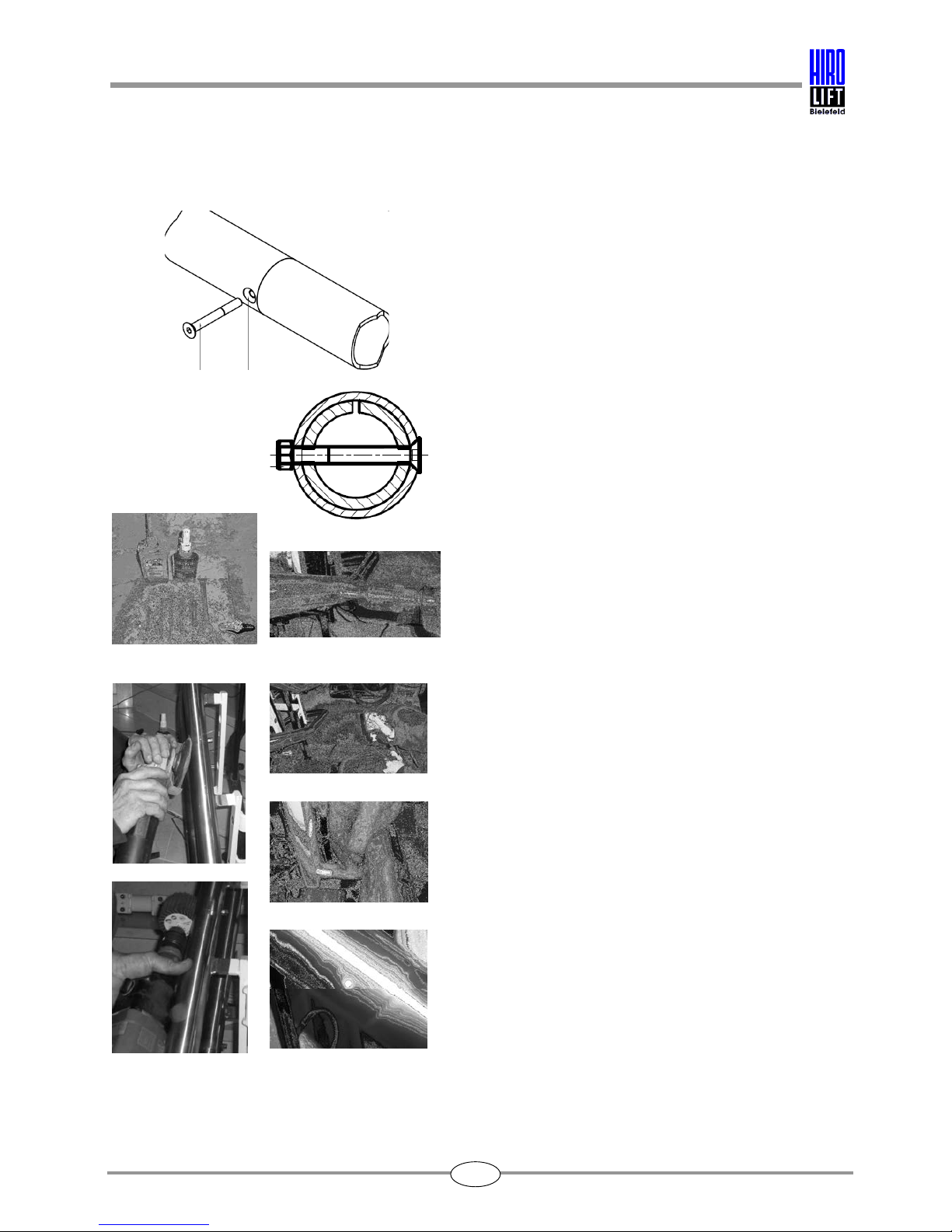
For joining the guide rail tubes together, M6 x 50
mm countersunk bolts with M6 nuts are supplied in
the enclosed accessory kit.
The sleeve and the guide rail tube have a pre-
drilled bolt hole but the bore must be enlarged and
countersunk.
In order to drive in the M6 bolt, the bore in the
guide rail tube must be enlarged to 5.2 mm. The
front of the tube must be countersunk so that the
bolt head will be flush with the outside tube
surface, and the bore enlarged to 6 mm. The rear
hole must be tapped with a M6 thread.
After cutting the rear M6 thread, secure the M6
bolt with a medium-strength thread-locking
compound and tighten the bolt. The bolt must be
secured with a M6 counter nut to prevent the bolt
from loosening.
After fixing the bolt head, grind it with an angle
grinder and an abrasive brush to leave a surface
that is flush with the guide rail tube.
3. Assembly and installation procedure HIRO 160 Q
17
The dimensions for further aligning the guide rail
beams are given in the lift unit drawing.
At each join position between the guide rail beams,
the drawing gives the height dimension from the
stair tread to the centre of the lower guide rail tube.
The guide rail braces must be aligned
perpendicularly. The guide rails can be adjusted at
the fixings by altering the position of the clip.
Check all the dimensions specified in the drawing.
After adjusting the position of the guide rails, check
that all fixings and supports are tightened
sufficiently, and re-tighten all bolts and screws if
necessary.
Check the dimensions of the guide rail track for
accuracy (centre distance).
The centre distance, measured vertically from the
centre of the upper guide rail tube to the centre of
the lower guide rail tube, must be 250 mm.

3. Assembly and installation procedure HIRO 160 Q
18
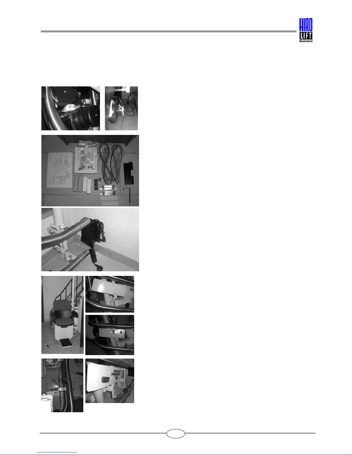
3.5 Installation of chair
Please carry out the following steps to install the
swivel seat assembly:
Attach the swivel seat assembly to the drive unit
with four fixing screws.
Connect the armrest controls, swivel seat switch
and swivel seat motor to the drive unit using plug-
in connections.
Insert the seat assembly between the U-bolts of
the drive unit, as shown in the pictures.
Ensure that no cables are damaged.
Fix the seat assembly in position at the side with
the four hexagon socket screws.
3. Assembly and installation procedure HIRO 160 Q
19
Connect the plug-in connections for the armrest
controls, swivel seat switch and swivel seat motor,
as shown in the picture.
In the case of lift units with a swivel seat in a
centre position, there is an additional
potentiometer at the pivotal point for detecting the
position of the swivel seat. Connect this plug, too,
with its counterpart.
The lift can be moved to the lower access point
using the emergency operation key.
Once the desired position has been reached, mark
this position for installing the charging points and
the magnets (lift stop).
3. Assembly and installation procedure HIRO 160 Q
20
3.6 Installation of upper/lower lift stops
The positive/negative charging pins and the
emergency limit switch can be seen in the picture.
The accessories kit supplied contains the following
parts:
1. Charger unit
2. Wall mount for charger unit
3. Cable for the charging stations
4. Charging bars
5. Magnets
6. Radio transmitter and wall mount
7. Emergency end buffers
8. Bolts and screws and plug kit
9. Circuit diagram
Install the charger unit with the wall mount near the
guide rails (lift stop).
The plates for the magnets and charging bar at the
lift stops have been factory-fitted in the lift stop
area.
The emergency contact strip and the limit stops
(buffers) have been factory-fitted at the upper and
lower lift stops.
At the lower stop, the charging bars and the
magnets still have to be fitted.
Fit the long magnet approx. 120 mm before the
(round) magnet that is located at the lift stop.
After the learning run has been carried out, the lift
always stops at the centre of the round magnet.
Position the charging bars (positive pole at the
top/negative pole at the bottom) at the "centre of
the charging pins" and connect them to the
charger unit.
Table of contents


