Lippe Lift LL12 User manual

Operating manual LL12 1/18 Version 1.6 (01/2017)
Operation of the LL12 stair lift
Contents Page
1 General............................................................................................................... 3
1.1 Technical data..................................................................................................... 5
1.2 Ambient conditions............................................................................................. 5
1.3 Testing obligations.............................................................................................. 5
2. Use as intended................................................................................................... 5
2.1 Transport profiles................................................................................................ 6
2.2 Inappropriate use................................................................................................. 6
2.3 Operator qualification......................................................................................... 6
2.4 Product description.............................................................................................. 6
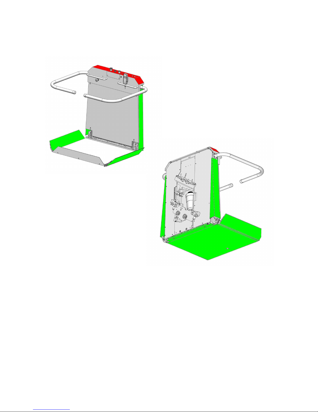
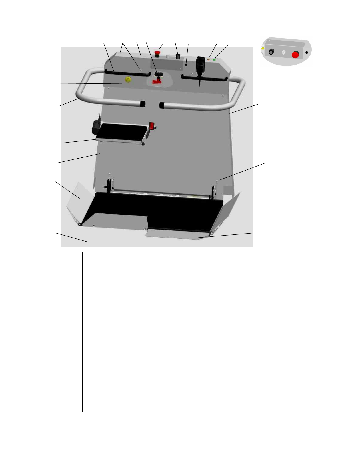
2.5 General overview of the platform lift.................................................................. 7
3 Safety................................................................................................................... 8
4 Operation............................................................................................................ 10
4.1 Main switch.......................................................................................................... 10
4.2 Deep discharge protection and charging.............................................................. 10
4.3 Checking the loading / overload protection………………................................. 10
4.4 Battery charger..................................................................................................... 10
4.5 Fetching and sending the platform lift................................................................. 11
4.5.1 Folding procedure……........................................................................................ 12
4.6 Travelling with the platform lift.......................................................................... 13
4.7 What to do in the event of an unexpected standstill............................................ 13
4.7.1 Hand wheel operation……………….................................................................. 13
4.7.2 Evacuation ………………................................................................................... 15
5 Options / Extras.................................................................................................. 16
5.1 Lateral drive-on ramp........................................................................................... 16
5.2 Folding seat……………....................................................................................... 16
6 In the event of a malfunction............................................................................. 17
7 Acoustic warning signals.................................................................................... 17
8 Services performed on your platform lift at a glance...................................... 18
! Important !
Please read the operating manual before using the lift.
Also make sure that each user of the lift has read and understood the operating manual.
No rights whatsoever can be derived from this operating manual.
This is a translation of the original German operating instructions

Operating manual LL12 2/18 Version 1.6 (01/2017)
EU declaration of conformity for machines
(EU machinery directive 2006/42/EC)
The manufacturer
Lippe Lift- und Anlagenbau GmbH
Weststrasse 48, D-32657 Lemgo,
hereby declares that the following machine
Inclined stair lift / platform lift / type LL12
conforms to all stipulations of the directive named above
conforms to the stipulations of the following additional directives:
EMC directive 2014/30/EU
Low-voltage directive 2006/95/EC
The following harmonised standards were applied or their protective goals were attained:
EN 81-40 (2009) EN 349 (2008)
EN ISO 12100 (2010) EN ISO 13850 (2007)
EN ISO 13857 (2008) EN 60204-1 (2007)
The following notified body: TÜV AUSTRIA SERVICES GMBH (IDF no.: 0408) was employed
for:
EU type testing, test report no..: TÜV-A/MHF/MG 13-05307
Responsible for the documentation: Lippe Lift- und Anlagenbau GmbH (Documentation Dept.)
Weststrasse 48, D-32657 Lemgo
Lemgo, 03/09/2009
_______________________
F.-W. Mueller (Managing Director)

Operating manual LL12 3/18 Version 1.6 (01/2017)
Manufacturer
Dead weight of
the platform
Load-carrying capacity
of the platform
Serial number
Year of manufacture
Type designation
Type of machine
General
The rating plate provides the most important information about the platform lift.
Field for details of the importer/dealer
1.

Operating manual LL12 4/18 Version 1.6 (01/2017)
The LL12 platform lift is equipped with many sensitive surfaces. Here is an overview:
RED = integrated in the safety circuit (further travel is not possible if activated)
GREEN = direction-related power-off (the lift can travel in the opposite direction)
If one of the direction-related switching surfaces (item 2 / green) is activated, the platform
stops moving and an acoustic warning signal is activated. After two seconds, the platform
drives without any command for 1.5 seconds in the opposite direction and stops. Only then is
the acoustic warning signal deactivated. The ‘release drive’ phase can be aborted only by the
activation of another switching surface, a safety switch or the emergency stop.
After the ‘release drive’ is finished, a travel command contrary to the last active travel
command must be given in order to resume travel.

Operating manual LL12 5/18 Version 1.6 (01/2017)
Technical data:
Permissible loading capacity: max. 225 kg (standard is 160 kg)
Continuous sound pressure level: < 70 dB (A)
Vibrations: < 0.5 m/s² (measurement inaccuracy ± 3%)
Speed: approx. 0.1 m/s
Platform voltage: 24 V DC
Battery charger voltage: 230 V AC (55 W)
Ambient conditions:
Temperature range: 0 °C to +40 °C
Rel. humidity: max. 90% non-condensing
Place of installation: Interior area
Testing obligations
Whether or not the LL12 platform lift is subject to an obligatory test depends on the respective
national regulations and is the user’s responsibility. These regulations must be checked and
adhered to. In Germany, a test is obligatory for systems with a lifting height of ≥ 3 m.
In each case, proof must be provided and documented in accordance with EN81-40 before the
first use.
The LL12 platform lift is to undergo maintenance in accordance with the maintenance
instructions at least once per year. We recommend that you take out a service contract with
your dealer.
Use as intended
The LL12 platform lifts are intended for the transport of wheelchair users and/or people with
reduced mobility.
The platform travels between fixed access points along a permanently installed rail, which is
implemented straight. The platform is guided over the stairs or an accessible inclined surface
by the running rail.
The system may only be operated by persons who have been instructed how to do so.
2.
1.1
1.2
1.3

Operating manual LL12 6/18 Version 1.6 (01/2017)
The following transport profiles are foreseen:
Transport of one person sitting in a wheelchair
Transport of one person sitting on the folding seat.
Transport of one person standing on the platform, provided that there is sufficient
headroom and that the person has sufficient standing stability and can hold the hand
grips securely (a separate set of documents is required, available on enquiry).
Transport of an additional person, provided that there is sufficient room on the
platform and that the permissible loading capacity is not exceeded.
A usage profile of 10 start-ups per hour is foreseen (with distances covered of max. 5 m for
each start-up). In the case of longer distances covered, the number of start-ups should be
reduced accordingly (and linearly).
The LL12 chair lift may be only operated if danger due to falling objects (such as flower pots)
is ruled out.
Inappropriate use must be prevented, e.g.:
Exclusive use for loads (if, in rare cases, loads such as shopping or beverage crates are
transported, it is essential to ensure that the load is sufficiently stable and that the
permissible loading capacity is not exceeded).
Loads that protrude beyond the surface area of the opened base may in general not be
transported (e.g. large pieces of furniture).
The LL12 platform lift is not a toy (children).
Operation in potentially explosive atmospheres
Operation outdoors
Operator qualification / technical personnel / qualified persons
The operator of the chair lift must have unrestricted mental abilities. Operators with seriously
impaired vision may be transported only with an attendant, whereby the attendant issues the
drive commands. Furthermore, the operator must have read and understood the operating
instructions.
Technical personnel and/or qualified persons are described in the assembly and service
manual.
Product description
Our products combine the requirements for overcoming stairs with outstanding integration in
the familiar environment in an appropriate way.
The maximum permissible load-carrying capacity is 225 kg, standard is 160 kg (measuring
point for this is the centre of the platform base).
The continuous sound pressure level is less than 70 dB (A).
We recommend that you take out a service contract. This guarantees the technically optimum
condition of your LL12 stair lift by means of regular maintenance. The maintenance interval is
once a year.
2.1
2.3
2.2
2.4

Operating manual LL12 7/18 Version 1.6 (01/2017)
Item Designation
1 Control unit
2 Key switch
3 Emergency stop button
4 Main switch (located inside)
5 Platform hood
6 Handle
7 Emergency call
8 Left-hand safety barrier
9 Cover for motor / controller (front cladding)
9.1 Folding seat (option)
10 Left-hand drive-on ramp
11 Contact base
12 Lateral drive-on ramp (option)
13 Plug seal
14 charging fuse
L1 Lamp: main switch ON
L2 Lamp: overload – load capacity exceeded
S1 Bolted connection – platform hood (4x)
S2 Bolted connection – front cladding (4x)
1
L2
6
5
4
3
2
10
9.1
8
7
12
11
L1
S
1
13
9
S2
1
4

Operating manual LL12 8/18 Version 1.6 (01/2017)
3. Safety and special instructions
Although your lift meets the latest safety regulations, it is essential that you observe
the following safety instructions:
Put the lift into operation only after reading the operating
instructions and adhere to the operating instructions.
Never exceed the permissible loading capacity.
(Residual danger: breakage/failure of the brakes)
Operate the lift only when seated (see transport profile for
exceptions)
Do not use the lift in the case of fire.
Do not allow loosely hanging articles of clothing to get near to the
running rail and the platform when the lift is moving.
(Residual danger: trapping of loose clothing, etc.)
Fold up the lift when not in use.
(Residual danger: tripping over)
Never place your hands near the running rail when the lift is moving.
(Residual danger: crushing)
Be sure to observe the track in the direction of travel when
travelling.
(Residual danger: crushing)
Do not remove, cut through, deform, or use undue force to operate
parts of the lift, cladding parts or operating elements.
Do not push the barriers with undue force, neither while travelling
nor when raising or lowering them.
(Residual danger: falling from the platform)
Stop the drive command immediately if there are obstacles or
articles in or on the track or platform or in the driving area.
(Residual danger: crushing)

Operating manual LL12 9/18 Version 1.6 (01/2017)
Do not remove any labels or signs belonging to the lift.
Have repairs carried out exclusively by specialists.
Do not allow any parts of the body, wheelchair or loads to protrude
beyond the base of the platform.
Do not make any unnecessary movements on the platform, such as
rocking or swinging.
(Residual danger: falling from the platform)
Remove dirt from the lift with a little polish or a damp cloth, not
with a water jet.
The load-bearing equipment and track must be sufficiently well lit
by daylight or electric lighting. The electric lighting must be
independent of timer circuits. Minimum 50 lux at the entry and exit
points or in accordance with the national employee protection
regulations.

Operating manual LL12 10/18 Version 1.6 (01/2017)
4.1
4.2
4.3
4.4
Main switch
The main switch (red key) is located inside the platform, behind the cover (p.7, item
4). The key can be removed by turning it anti-clockwise, thus disconnecting the
power supply. (For opening the cover, sees 4.7.1). The main switch must be actuated
by technical personnel.
Deep discharge protector and charging
The LL12 platform lifts are equipped with automatic battery chargers. Charging takes
place automatically when the platform lift drives into a loading station. The batteries
do not require any care.
All LL12 platform lifts are equipped with an acoustic deep discharge protector. This
acoustic signal generator is intended to protect the batteries against deep discharge.
If the battery voltage drops below 22 V, a beep sounds at intervals of approx. 5
seconds. In this case you should drive immediately to the next charging station – if
possible the lower charging station – and allow the lift to charge up there for several
hours (this takes place automatically in the charging station). The beep stops after
proper charging. The sound can be turned off by pressing the emergency stop button;
this has no influence on the charging process.
Checking the loading / overload protection
The LL12 platform lift is equipped with an overload protector (acoustic and visual).
On activation the orange lamp on the hood goes out (p.7, item L2). In addition, the
internal beeper emits a continuous tone in the case of overload. This is based on the
entire load being in the centre of the base of the platform. Reduce the weight if the
overload protector is triggered. It may be sufficient just to shift the weight towards
the running rail.
Battery charger (indicator lamps)
The indicator lamps on the battery charger indicate the respective condition of the
battery charger. Distinction must be made between different versions of the battery
charger.
The meaning of the various colours or indicator lamps is shown on the battery
chargers. The installer will explain this to you in detail once again during the
instruction.
Note: An acoustic signal sounds if the lift, outside a station, is not charged 30
seconds after the last motor movement.

Operating manual LL12 11/18 Version 1.6 (01/2017)
4.5 Fetching and sending the platform lift (standard version)
Before each journey, make sure that the acoustic warning signal works. The LL12
platform lift can be fetched from or sent to another station from any station. To do
this, the key switch must be inserted at the respective station, turned in the
appropriate direction and held in this position.
The platform lift does not react immediately, but after a delay time of approx. 2
seconds.
Note: The platform lift drives from the external control point only in the folded up
condition, i.e. the base of the platform must be folded up and the safety
barriers folded downwards.
Note: an LED is mounted on the radio transmitter for fetching/sending the chair lift.
GREEN: batteries are OK
ORANGE: the battery power is diminishing; renew the batteries at your earliest
convenience
RED: the battery power is very low; replace the batteries immediately
Fetching and sending the platform lift (special version 1) [via the external control
unit, only with 3-position key switch (p.7, item 2) for a trip with the platform open
via the external control unit]. This option must be activated by a specialist inside the
controller. It must be ensured that no third person can suddenly get/jump into the
path of the lift. Condition: driving area is 100% in view !!!!
The key switch (p.7, item 2) is to be set to position -II-, otherwise as in 4.5.
Fetching and sending the platform lift (special version 2) [via the internal
controller, only with 3-position key switch (p.7, item 2)]. This option must be
activated by a specialist inside the controller.
The platform can be driven via the internal controller in the folded up condition. The
key switch (p.7, item 2) is to be set to position -II- in order to do this. The platform
lift can now be driven via the internal controller (p.7, item 1).

Operating manual LL12 12/18 Version 1.6 (01/2017)
4.5.1 Folding procedure
In the case of the LL12 platform the base folds up and down electrically and the
safety barriers raise and lower electrically. This is performed by means of an UP or
DOWN command issued from a station (see also paragraph 4.5), or via the internal
controller in the case of special version 2. The control button must be pressed and
held (so-called jogging mode) until the folding procedure is complete.
If a malfunction should occur during the folding procedure, the platform must be
folded up or opened manually (see below) and customer service must be informed.
The folding procedure at a step can/may only be carried out by an attendant.
Proceed as follows in order to fold up the platform by hand:
a) Place the safety barriers in the horizontal position.
b) Fold up the base of the platform.
c) Lower the safety barriers so that they rest against the base of the platform.
Proceed in the reverse order to open the platform again and finally raise the safety
barrier at the desired access point right up to the top (vertical).

Operating manual LL12 13/18 Version 1.6 (01/2017)
4.6 Travelling with the platform lift (standard version)
Before each journey, make sure that the warning signal works. The following control
elements are located on the platform:
a) Key switch Function -I- and -0- (p.7, item 2)
b) Control unit Function UP and DOWN (p.7, item 1)
c) Pushbutton EMERGENCY STOP (red knob) (p.7,item3)
After driving the platform, insert the key and turn it to position -I-:
! In the case of the LL12 platform, the safety barrier closes electrically when the
button is pressed and held in the desired direction of travel. The platform lift
begins to move once the barrier has closed.
Upon reaching the destination station:
! The platform lift stops automatically (the respective position is set during the
installation).
!In the case of the platform, press and hold the button until the safety barrier has
opened.
Travelling with the platform lift (special version 1) [via the external control unit,
with 3-position key switch (p.7, item 2) for a trip with the platform open via the
external control unit]. This option must be activated by a specialist inside the
controller. It must be ensured that no third person can suddenly get/jump into the
path of the lift. Condition: driving area is 100% in view !!!!
The key switch (p.7, item 2) is to be placed in position -II-, otherwise the procedure
is the same as described under ‘standard version’, with the difference that only the
external control unit is used here.
Travelling with the platform lift (special version 2)
The key switch (p.7, item 2) is to be placed in position -I-, otherwise the procedure is
the same as described under ‘standard version’.
4.7 What to do in the event of an unexpected standstill, e.g. due to a power failure?
We recommend that a working mobile telephone be carried in order to alert the
rescue services.
4.7.1 Manual operation / operation with hand wheel
The LL12 stair lift can also be operated manually. Manual operation must be
performed by technical personnel! The procedure is as follows:
a) Press the EMERGENCY STOP button (p.7, item 3) on the platform.
b) The bolted connection of the platform hood must be remove using the
hexagonal wrench (provided in the envelope).

Operating manual LL12 14/18 Version 1.6 (01/2017)
c) The platform hood is to be raised and secured against falling down by means of
the insertable arms.
d) The bolted connection of the front cladding must be undone using the hexagonal
wrench (provided in the envelope) and the cladding removed.
d) The brake venting lever is to be pressed upwards or downwards whilst at the
same time turning the hand wheel on the end of the motor shaft (see illustration
below).
In doing so, the direction of travel should always be towards the lower station (less
energy expenditure when turning the hand wheel). The respective direction of
rotation is indicated directly on the hand wheel.
Note: If the cause of the standstill is not clear, it should be assumed that the safety
arrester has been triggered and that its safety switch has led to the lift switching off.
The safety arrester may only be reset by technical personnel. In this case,
proceeded as described in a) to e) above, but first turn the hand wheel in the UP
direction (until the lift has moved approx. 5 cm along the rail), after which the hand
wheel can be turned in the DOWN direction.
Prop
Brake venting lever

Operating manual LL12 15/18 Version 1.6 (01/2017)
4.7.2 Evacuation / only by technical personnel
Proceed as follows in order to help the operator out of the lift:
Press the EMERGENCY STOP button (p.7, item 3) on the platform.
Remove the plug seal (for the emergency unlocking) on the front cladding
on the uphill side using a screwdriver or similar.
Press the lever shown in the picture (below right) downwards using a
suitable tool.
The operator can now be helped out at the uphill side.
The platform must be folded up by hand so that the lift does not block the staircase
(see 4.5.2).

Operating manual LL12 16/18 Version 1.6 (01/2017)
5
5.1
5.2
Options / extras
Depending upon requirements, the LL12 platform lifts are also equipped
with the following extras.
Lateral drive-on ramp
In some cases (staircases) it is not possible to drive onto the platform over
the two standard drive-on ramps due to the space in front of the first step.
In these cases an additional drive-on ramp is to be mounted on the long
side of the platform (p.7, item 12).
Folding seat
All of our platform lifts can be equipped or retrofitted with a folding seat if
desired (p.7, item 9.1). The folding seat is intended as a seat for non-
wheelchair users who wish to use the platform lift. When folded up, the
seat lies against the platform wall to save space. The folding seat is
equipped with a seat belt, which must be fastened while travelling if the
user is not able to hold on to the barrier or the hand grip with a hand.

Operating manual LL12 17/18 Version 1.6 (01/2017)
6. In the event of a malfunction
Malfunction Possible cause Remedial action
Lift does not
function at all
Is the key on the control unit set
to -I- and are the others set to -0-
or removed?
Set the key switches correctly (see
4.5 or 4.6)
Is the EMERGENCY STOP
switch unlocked?
Unlock the EMERGENCY STOP
switch by turning or pulling
(depending on the design)
Is the main switch for the lift set
to -I-?
Turn on the main switch (see 4.1)
Batteries defective or deep
discharged
Replace the batteries (technical
personnel)
Safety arrester has triggered Inform technical personnel
Are the safety barriers in the
horizontal position?
Actuate the safety barriers again or
move them slightly up or down
Lift does not
start when
platform is
unfolded and
occupied
Are the drive-on flaps freely
movable?
Press the drive-on flaps slightly
outwards. Drive in the opposite
direction.
Load-carrying capacity exceeded Reduce weight
Lift does not
fold
automatically
Are all key switches at -0-
except at the control station
selected by you?
Set the key switches correctly (see
4.5 or 4.6)
In the case of radio-controlled
control stations: are the batteries
OK?
Replace the transmitter batteries
If you cannot repair the error yourself in this way, please inform your customer service.
7. Acoustic warning signals
Duration
[sec.]
Pause
[sec.]
Reason Remedial action
0.1 5.0 Low battery voltage
(see also 4.2)
Drive to the charging station and
charge the batteries
0.1 0.5 Acoustic drive warning -----
0.1 0.25 Release drive (see page 4 for
description)
-----
2x briefly 4.0 Overtemperature of
motor/electronics, or defective
fuse
It is possible to resume driving after a
cooling down period of approx. 5 min.
(If cooling is insufficient, the cooling
period is extended by a further 5 min.)
3x briefly 4.0 Faulty electronics/motor Inform customer service
Continuous
tone
---- Emergency call by means of
beeper on the platform, or
overloading
Release the emergency call button.
Shift centre of gravity closer to the rail
or reduce the weight
Note: The acoustic warning signal can be suppressed by pressing the emergency stop button;
the charging procedure is maintained (exception: continuous tone).

Operating manual LL12 18/18 Version 1.6 (01/2017)
8. Services performed on your Konstanz stair lift at a glance
Installed on: Serial no.:
Installed by: TÜV acceptance on:
No. Date Service performed Signature
1
2
3
4
5
6
7
8
9
10
11
12
13
14
15
16
17
18
19
20
21
22
23
24
25
26
27
Table of contents
Other Lippe Lift Stairlift manuals
Popular Stairlift manuals by other brands

Atlas
Atlas 500 Series installation manual

Harmar Mobility
Harmar Mobility Helix Series owner's manual

Minivator
Minivator 1000 series user manual

Lehner Lifttechnik
Lehner Lifttechnik DELTA User handbook

LIFTSHOP
LIFTSHOP T2 Installation, Operation and Preventive Maintenance manual

vimec
vimec V65 B.I. manual