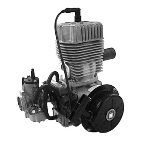
Hirth 210R User manual

'
Two
Cylinder
Engine
Models
210R
• 211R •
220R
• 171R
-Instructions-
Assembly
and
Disassembly
lntructlons
pour
le
Montage
et
Demontage
du
Moteur
~~
TEL
F
WISCONSIN
MOTOR
MILWAUKEE,
WISCONSIN
53246
SALES
AND
SERVICE
REPRESENTATIVES
FOR
HIRTH
ENGINES
ISSUE MM-331

Technical Data
Informations Techniques
Type
210
R
..•
Engine
output:
22
hp
(DIN)
Puissance:
nt
5500 rev'min
Bore: 2.480" (63 mm)
Ah'lsage:
Stroke: 2.52" (64 mm)
Course:
Piston displacement: 24.35 cu. in. (399 cc.)
Cylindree
Breaker
point
gap:
+ .
oo
2
11
(O
+
o.os
)
Ecartementaux
vis platinees: ·016 -4 -
mm
Ignition
timing:
Reglage d'allumage:
retarded 4 + 3
BTDC
(=
0,1 -0,2 mm
BTDC)
(= .004 r .0078"
BTDC)
advanced
22
I 3"
BTDC
(=
2.9 0.85
mm
BTDC)
(= .114 + .033" BTDCJ
Spark
plug:
for
normal operation: M 225 T 1 Bosch
Bougie:
for
heavy-duty operation. M 240 T 1 Bosch
Spark
plug
gap:
0.02
...
004"
Ecartement
des
electrodes:
(0.5
...
0.1
mm)
211
R
••.
220
R
••.
171
R
...
24 hp (DIN)
27
hp
{DIN)
36 hp
(DIN)
at
5250 rev min
at
5500 rev min
at
5500 rev mm
2.598" (66 mm) 2.756·· (70 mm) 3.031" (77
mm
)
2.52" (64 mm) 2.52u (64 mm) 2.68" {68 mm)
26.73 cu. in. (438 cc.) 30.08 cu.
m.
(493 cc.) 38.69 cu. in (634
cc
.)
.016 ± 002" (0.4 ± 0
05
mm) .016 ± 00211 (0.4 ±
CIIIS
mm) .016 ±
002
" (0.4 ± "
11
5 mm)
retarded 4 + 3"
BTDC
retarded 4 + 3
BTDC
retarded 4 3
BTDC
{=
0,1 + 0,2
mm
BTDC)
{=
0,1 + 0.2
mm
BTDC)
(=
0,1 -0,22
mm
BTDC
}
{=
.004 + .0078" BTDC)
(=
.004 + .0078"
BTDC)
(=
004
-r
.0085"
BTDC)
advanced 22
-r
3
BTDC
advanced 22 ... 3
BTDC
advanced 22 3
BTDC
(=
2.9
.....
0.85
mm
BTDC)
(=
2.9 + 0.85
mm
BTDC)
{=
2.9
0.85
mm
BTDC)
(=
.114 ......
033
11
BTDC)
(=
.114 t .033"
BTDC)
(=
.114 + .033"
BTDC)
M 225 T 1 Bosch M 225 T 1 Bosch M 225 T 1 Bosch
M 240 T 1 Bosch M 240 T 1 Bosch M 240 T 1 Bosch
0.02
+ .004"
0.02
+.004"
0.02
'r
.004"
(0.5
+
0.1
mm)
(0.5
+
0.1
mm)
(0.5
+ 0.1 mm)
REMARKS:
171
=
Model
171
R
REMARQUES:
22
=
Model
210
R,
211
R,
220
R
Printed
in
U.S.A.

Disassembly of motor
Remove
motor
from apparatus Remove attached
parts,
like
exhaust silencer, corburetor,
electric
starter
etc.
2.
Screw assembly angle
1ron
W 115 into the base tap holes
and put
motor
with angle
1ron
into the vise
(fig
1)
Fan housing
3.
Lift
fan housing
with
attached
recoil
starter
after unfastening
the
fill.
head screws
(4
type
22,
6 type 171)
with
special hex
spanner 5
DIN
911.
Guide
plates
4. Pull
off
spark plug hood
w1th
protecting
cap
from spark plug.
Screw
off
the two hex. screws
with which the
ignition
cable
is
held on the
guide
plate
. Loosen
all set screws
with
which the
gui
de
plates and the exhaust manifold
are
fastened.
Take
off
intake mamfold
(for
K wrench and socket
wrench
SW
13;
SW
= width
of
wrench in mm).
171: Remove the 4 studs
for
fastening
of
the exhaust
manifold, e.
g.
by means
of
2 hex. nuts, turned
against each other, so
that
the guide plate. lying
behind, can be taken off.
Cylinders
and
pis
tons
5. 22:
Lift
off
the
two
cylinder
heads
with
cylinder
head
gasket
after
loosening the 8 fill. head screws
of
each.
Screw
off
the 8 hex. nuts with which
the
cylinders
a
re
fastened
to
the crankcase. (annular wrench
sw
13
).
171:
Lift
off
the 2
cylinder
heads
with
cylinder
head
gaskets after loosening the
four
hex. screws
(SW
5)
and the
four
hex. nuts
(SW
13).
Before
disassembly mark cylinders and the pistons
belonging
to
them with I (ignition side) and II (drive
si
de)
so
that
the parts cannot be interchanged when
they are used again.
L1ft
off
both
cylinders with cylinder
bottom
gaskets.
Take
off
the gudgeon
pin
guard.
First
disassemble
piston
of
cylinder
II. Press
out
gudgeon
pin
with
assem
bl
y pin W
39
/4 from
drive
side towards
igni-
tio
n si
de
.
If
necessary
top
lightly
with
hammer, pressing
hand against piston.
171: Disassemble piston
of
cy-
linder
I correspondingly. Push
needle cage out
of
the small
connecting rod eye and in or-
der
to
keep
it
put
it
on
the
corresponding
connect
ing rod.
22:
Place piston
of
cylinder I
so,
that
the connection rod,
when
it
is pushed out, points
toward the opening
of
the
blo-
wer
space. The disassembly is (2}
the same
as
with piston II.
(Fig.
2)
.
Demontage du Moteur
1. Depose du moteur depose
des
accessoircs
leis
que
silencieux d'echappemcnt, carburateur demarreur
electrique.
(1)
2 Fixer
le
gabari W 115 aux trous
de fixation du socle serrer le
gabari avec le moteur dans
l'etau (Fig. 1).
Capot
de Ventilateur
3 Demonter
le
capot
de ventila·
leur
avec le Iancour a main en
devissant
les
vis a 6 pans creux
(4
pieces type
22,
6 pieces type
171) au moyen
de
Ia cle male
J>
5
DIN
911
To
le
guide
d'air
4.
Retirer le chapeau de bougie,
avec sa
coiffe
de
protection,
de
sur Ia bougie. Devisser les bou-
gies. Devisser les deux vis fixant
le
cable
de
bougie sur Ia
tole
guide
d'ai
r.
Devisser toutes
les
vis maintenant
les
toles
guide
d'
air
et
le
collecteur
d'echappement; demonter le
collecteur
d'admission
(cle
plate
et
cle a
pipe
ouv
13
(ouv ouverture
des
cles en milimetres).
171
: Devisser
les
4 goujons de fixation du
collecteur
d'echappement en se servant de deux ecrous, serres
l'un sur !'autre afin do pouvoir
demontcr
Ia
tole
guide
d'air
du fond.
Cylindres
et
Pist
ons
5.
22
: Demonter les deux culasses avec leur
joint
en
dev1ssant les 8
vis
a 6 pans
creux
(cle 5 mm). De-
visser les 8 ecrous
par
lesquels les cylindres
sont
maintenus au
carter
(cle a oeil multipan ouv
13)
.
17
1:
Demonter
les
deux cuiasses avec leur JOint en
devissant les 4 vis a 6 pans
creux
(cle 5
et
les 4
ecrous a 6 pans (cle de 13).
Avant de
proceder
au demontage des cylindres
et
des
pistons apparies il y a lieu de
proceder
a
leur
reperage, en les marquant I
cote
allumage II cOte
prise de force, afin
de
ne pas les
intervertir
lors du
remontage, deposer les deux cylindres avec leur
joint
d'embase.
Retirer
les
jones
d'arrct
des
axes
de
pi-
stons Demonter le piston du
cylindre
II en
premier
.
En se servant
du
chasse axe W 39/4 chasser l'axe
dans
le
sens
prise
de
force-allumage. Au besoin
maintenir le piston d'une main
et
en donnant
des
petits
coops
de
marteau
faciliter
!'extraction.
171: Pour le demontage du P•-
ston du cylindre I
proceder
de Ia
m6me
fa<;on.
Retirer
Jes
cages
a aiguilles
de
l'ceil
du pied
de
bielle,
il
est
preferable
de
les
remettre
de
suite sur l'axe
de
piston respectif.
22: Placer le piston du cyl•ndre I
de
fa<;on
telle
que l'axe puisse
lltre
chassee vers J·ouverture
de
Ia ventilation. Pour
le
demontage
proceder
de
Ia meme
fa<;on
que
pour
le demontage du piston du
cy
lil"dre II (Fig. 2).

Fan wheel
6. Screw
holding
dev1ce
for
fan wheel W 116 (see
fig. I) to the crankcase. Take
off
catch
with
locking
plate by
loosenmg
the fill. head screws Take
off
the
cover
plate
, lying behind the catch
loosen
the
heiC
nut
w1th
which the fan wheel
1st
fastened w;th hex.
spanner
(SW
24).
a)
Fan wheels
of
an
older
type with only 3
tapped
holes 6 mm
for
fastening
of
the catch.
Place
extroctorW
113
with the 3 hex screws
into the 3 threads
of
the fan wheel.
loosen
fly wheel by turning
the pressing screw
of
the
extractor
towards
the right. Take
off
hold1ng dev1ce so that
the fan wheel can be
taken
off
(fig. I)
b) Fan wheels with 3
lld-
ditional
tapped
holes
8 mm.
Screw
off
holding
de-
VICe
W 116. Firmly
screw
extractor
W 120
to
the hub
of
the fan
wheel with the 3 hex
screws and take
off
fan wheel as shown
1n
f1gure
3.
Take
out
key in the crankshaft.
loosen
the
two
set
screws with which the arma-
ture pl1\te is screwed down in the housing.
Ignition
7.
Take
motor
out
of
the
v1se
and screw
off
assembly
angle iron.
22:
Screw
assembly angle
iron
as shown on figure
11
assembly
to
the
two
drive
side studs
for
the
cylinder
and again place
motor
into vise.
171: Place assembly angle irons W 115
over
the
two
tie rods on
the
drive
side and
tighten
by means
of
two
tubes 140 mm long and hex. nuts. Put
motor
back
into
vise (see fig. 9 assembly).
8.
Pull
off
protecting
cap
and spark plug
hood
as well
as the clamp on the 1gnihon cable and insulating
hose
loosen
the
4 tapp1ng screws with which the
ignition
coils
are fastened.
Pu'l
out
of
the sockets
of
the
ignition
coils
the
wire
plug
with
short
circuit
and
generator
cable. Then
the
two
ignition
coils
can be
pulled
off
with
ignition
cable
and the insulating hose
pulled
over
them
Take
off
rainprotection
capes and insulating
hosM
from the
generator
and
short
circuit
cables. Then
the
two
cables
belonging
together
(short
circuit
and
one
generator
cable
each) can be
pulled
through the
boring
in the housing
into
the
ignition
space.
After
pulling
out
the
light-,
ground-
and short
circuit
cables
2
Ventilateur
6.
Fixer
le
d1spositif de
blocage
du venttlateur W 116
commo indique Figuro 1, devisser los vis a 6 pans
creux,
retirer
l'entraineur
et
Ia
tole
frein
d'ecrou;
re-
tirer
Ia
tole
de
recouvrement so trouvant
derriere
l'entraineur. Devisser l
'e
crou a 6 pans fixant
le
ven-
tilateur
au moyen
de
Ia cle plate de
24
mm.
a)
Ventilateur
d'execution
plus
ancienne avec seule-
ment 3 trous taraudes
pour
Ia fixation
de
l'en-
traineur
.
(Filetage
de
6 mm).
(3)
171
Monter
l·extracteur W 113
en vissant
les
trois
bou-
lons de l·extractP.ur dans
les
trois
trous sur le mo-
yeu du ventilateu
r.
Arra-
cher le
ventilateur
en
tournant
Ia
v1s
de
pres-
sion de l'extracteur
vcrs
Ia
droite
Demonter
le
dispositif
de
blocage
du ventila-
teur
afin
de
pouvoir
en·
lever
celui-ci.
Fig. 1
b)
Ventilateur
avec 3
trous
taraudes supplementai-
res
(Filetage
de
8 mm).
Demonter le
dispositif
de
blocage
du
ventila-
teur
W 116
Monter
l'ex-
tracteur
W 120 en
le
vis·
san! au ·moyeu par les
trois vis a 6 pans.
Arra-
cher le ventilateur
COI"lmC
indique.
Fig.
3.
Reltrer Ia
clavette
Woodruff
de
Ia
rainure du vile-
brequtn. Devisser les 2 vis fixant le plateau
porte-
induits au carter.
Allumage
7. Retirer
le
moteur de l'etau, enlever le gabari.
22: Fixer le gabari comme indique
figure
11
aux deux
goujons
cote
prise
de force.
Replacer
le moteur dans
l'etau
171 : Passer
le
gabari
W 115
sur
les deux
goujons
de
cylindre
cote
prise
de force,
le
serrer au moyen
de
deux
bouts
de
tube
de
140
mm
et
des
ecrous a
6 pans.
Replacer
le moteur dans l'etau.
(voir
Fig. 9
montage)
8.
Demonter
Ia
co1ffe de
protection
, le chapeau de
bou·
g1e
ainsi
que
Ia
bride
de f1xation
du
fil
de bougie
ct
Ia
gaine isolante
Dev1sser les 4 vis taraud fixant les bobines d'allu-
mage.
Retirer
de
leur
prise
sur
Ia
bobine
les fiches avec
les fils
coupe
circuit
et
les
fils
de
Ia
generatric\3.
les
deux bobines avec
les
fils d'allumage
et
les
ga nes isolantes peuvent maintenant etre retirees.
Retirer le capuchons pare-pluie et les gaines
ISO·
lantes des fils de Ia generatrice
et
du coupe
circuit.
Par
Ia
suite on
pourra
retirer
les
deux paires
de
fils
(1
coupe
c~rcu
t 1
generatnce)
du caoutchouc passe
cable
du
carter
en les passant cote altumage. Apres
avoir
retire les fils lumii!re, masse
et
coupe
c rcuot

the armature p:ate can be taken
out
A
drop
of
oil
at
the rubber bushmg
of
the cables will make
it
easier
to
pull the cables through the openings. First take
off
wireplugs and insulating hose
if
they are present.
If
cables and armature
plate
are in
good
state
no
further disassembly
is
necessary
Crank
case and cranksha
ft
9.
Unscrew
the 10 fill head
screws (with special spanner
5
Dl
N 911)
at
the packtng
strip
of
the crankcase.
After
that
loosen the
10
fill. head screws
(with special spanner 6 DIN
911) with which the
two
halves
of
the crankcase are screwed
together. Take
off
the
upper
half
of
the crankcase Take
away the
sheet
metal ring l
o-
cated
in the
ignition
space.
Take
out
crankshaft,
if
neces-
sary use a hammer handle
(fig. 4). Pu I
off
the
exterior
rubber rings from the
crank-
shaft.
If
necessary, pull
off
the
ball
bearing
on
the
ignition
side
with
extractor
W
107
and
inset W
107
/15
(fig.
5)
With
the ball
bearing
on the
drive
side,
first
the
guarding
(in type
22
1n
addttion also
the
circlips
from the
exterior
ring
of
the bearing) must be
taken
off
.
Then
place
pressure
devtce W 10514
into
the
bo-
ring
of
the crankshaft, place
extractor
W
107
and
draw
off
bearing
as shown in figure.
10. Wash
motor
parts in
gasoline
used
for
cleaning purposes.
Carefully
scrape all residues
of
the sealing material.
11
. Replace
damaged
parts
Assembly of motor
1. Pull
both
main bearing:> on
the
crankshaft
until
they touch
crankweb
22: Main
bearing
with
perfora-
tion
is
located
on the
drive
side,
with
perforation
towards
tenon
171:
Before
this a snap ring
62x2 DIN 472 must be
placed
on
the
dnve
side.
The
installation
of
the
bea-
rings is
done
in the following
manner
(fig.
6).
(5)
3
le plateau
porte-induits
pourra etre enleve Une
goutte
d'hui
le au caoutchouc passe
cable
facilitera
le passage
des
fils.
S'il
y a lieu,
enlever
les gaines tsolantes
et
les lan-
guettes
de
contact.
Au
cas
ou les
conduites
et
le
plateau
porte-induits
son\
en
bon etat.
II n'y a pas lieu d'etendre
le
demontage.
Carter
et
Vileb
requin
9 Devisser les 10 vi:; a 6 pans
creux du plan
de
JOint
du
vile·
brequin (cle
de
5
DIN
911).
Ensuite devisser les 10 vis a
6 pans creux assurant !'assem-
blage des 1
ft
carters, (cle de
6
DIN
911)
Sortir
l'etrier
en
tole
cote
allumage. Deposer
le
v:lebrequin au besoin en
s'aidant
d'un manche de mar·
teau
pour
le
sortir
(Fig. 4).
Retirer les JOints simmer des
extremites du
vilebrequin
St
necessaire
demonter
le roule
ment
cote
allumage au moyen
de
l'extracteur
pour
roulements
W
107
et
de
ses accessoires
W 107t15 (Fig.
5).
Pour
demonter
le roulement
cote
prise
de
force
,, y a lieu
de
retirer
d"abord le
circlt
'S
tnterieur;
pour
le
type
22
le
clips
de Ia rainure sur Ia bague
exterieure.
lntroduire
Ia piece
d'appui
W
105
4 dans
le
creux de
l'arbre
du vtlebrequin
monter
l'extracteur
pour
roulements
Arracher le roulement comma
indique.
10.
Laver soigneusement toutes
les
pieces a !'essence,
enlevor
avec precaution
toute
matiere
d'etancheite sur Ia surface
do
jo
inture.
11.
Remplacer toutes les piece!>
defectueuses.
Remontage
du
Moteur
1. Presser
1cs
deux roulements
sur
le
vilebrequin
jusqu'a
ce
qu'ils
vtennent
buter
contra
le
flasque.
22: Le Roulement
pnncipal
avec rainure sur
Ia
bague
ex-
terieure se monte
cote
prise
de
force,
Ia
ratnure vers le
bout
d'arbre.
171
:
Monter
d'abord
un
cir-
cltps
--::,
62x2 DIN
472
c6te
prise
de
force
Processus
pour
le montage des roulements
(Fig. 6).

Push
bearing
over
the
cone
of
the drive side tenon.
Screw
bolt
of
the
assembly
tool
W
112
into
the inner
threading
of
the crankshaft. Push the assembly
tool
over
the
bolt
until
it
touches the ball bearing. Then
pull back the
tool
as far as necessary so that the
pin
can be
put
through
tool
and
bolt.
Pull crankshaft
until the end
of
the
toolfront.
Then place
pin
into
the next
hole
in
the
direction
of
the crank web and
repeat act1on until bearing
touches crankshaft.
The
installation
of
the bearing
on the
ignition
side is
done
correspondingly.
However
the
bolt
of
the
tool
must
be
screwed
to
the
outside
shrea-
ding
of
the crank tenon. Then
on the
drive
side
place
snap
ring
30x1
,5 DIN
471
into
the
groove
of
the crankshaft and
in
case
of
motor
22
put
the
circlips
SP 72 DIN
5417
on
the
drive
side bearing.
2. Put
upper
part
of
crankcase -
as
described
in
point
7
(dis-
assembly) with assembly angle
iron
W
115
into the vise. Exa-
mine sealing surface
for
pos-
sible damage.
If
necessary
slightly
refinish. Put sealing
material Hylomar S a
32
M on
both
sealing surfaces.
Place crankshaft
into
upper
part
of
case (fig. 7).
22: Place
spacer
ring (1) with
opening
downward between
the
two
inside
spring
loaded
oil seals (Fig.
8)
.
171: Pay attention that
the
two
snap rings lying in the
middle
between the oil sealing rings
are placed in
their
grooves.
The
same applies
to
the two
snap rings on the drive side
(fig. 9).
Push sheet metal ring (2) (see
fig
8 and 9) into crankcase in
order
to
seal
off
ignition
space. Put on
lower
part
of
case.
(9)
4
Passer le roulement
sur
le
cone
de l'axe du vile-
brequin
cote
priser
de
force
visser Ia broche de
l'appareil
de
montage W
112
dans
le
creux
de l'axe
du vilebrequin. Passer
l'appareil
sur
Ia broche, !e
pousser
jusqu'a
ce qu'il vienne
buter
centre
le roule-
ment, revenir en arriere
de
fac;:on
a
pouvoir
passer
Ia
cheville dans le trou de
l'appareil
de montage
et
de
celui
correspondant
de
Ia
broche.
A !'aide des deux leviers
de
l'appareil
presser
le
roulement
jusqu'a
fin de course
de
l'ap-
pareil,
retirer
Ia
cheville
et
Ia
replacer
dans le
trou
suivant,
vers
le
flasque du vilebrequin,
continuer
le montage
jusqu'a
ce
que
le
roulement ait pris
sa
place
en venant
buter
centre
le flasque.
Le montage du roulement cote
allumage se
fait
de
Ia meme
fac;:on.
II
y a
pourtant
lieu
de
visser Ia broche
accessoire
de
l'appareil
de
montage
sur
:e
pas
de
vis exterieur de l'axe
du vilebrequin.
Monter
ensuite
un
circlips
C/J
30x1
,5
DlN
471
dans
Ia
rainure du
vilebrequin
cote prise
de
force;
pour
le
moteur
type
22,
manter le
clips
SP
72
DIN
5417
dans Ia rainure
sur Ia bague exterieure du
roulemen!.
2.
Comme
decrit
si no. 7 (Demon-
tage), serrer
le
gabari avec le
1
/2
carter
superieur dans l'etau.
Verifier
si le plan
de
joint
n'a
pas ete abime, au besoin, rec-
tifier
legerement. Enduire les
deux plans
de
joint
de
pAte
d'etancheite ,
Hylomar
Sa
32/
M;".
Monter
le vilebrequin
dans le
1
/ ~
carter
superieur
(Fig. 7).
22: Placer
l'etrier
en
tole
(1)
l'ouverture
vers
le
bas
entre
les deux
joints
Simmer
inte-
rieurs (Fig.
8)
.
171:
Veiller
a
ce
que
les deux
circlips
montes entre les deux
joints
Simmer
interieurs
scient
a
leur
place dans
Ia
rainure
sur
l'arbre du vilebrequin. II
en
est
de meme en ce
qui
concerne
le
circlips
cote prise
de
force
(Fig. 9).
Mettre
Ia
bague en
tole
(2)
Fig. 8
et
9,
servant a
l'etan-
cheite de Ia chambre
d'allu-
mage a sa
place
dans
le
1/!
carter.
Monter
le 1/t carter.
inferieur.

3.
First
screw down
lightly
the
ten inside hex screws wi
th
which
the
ha
lves
of
the case
10
,....-
are screwed together. The
tightening
of
screw is
done
in
the
order
shown in fig.
10
with
16,5*
0
-~
ftlbs (2,3'0•3 mk
g).
In-
sert
the
10
inside hex screws
at
the packing
strip
and
tigh-
lllilat;;=:;
ten 6,5•1•5 ftlbs
(0,9'
0•1
mkg).
Spr
ing loaded
oil
seal
4.
Slight
ly
oil
seal on
exterior
and
interior
diameter
and
in-
sta
ll with sealing
strip
towards
bearing. Put assembly
sleeve
W 114
over
the
shaft
tenon
and push spring loaded
oi
l seal
against the
bearing
(fig.
11
).
Take
off
sleeve. Press oil seal
with pressure pl
ate
W
37/8
and inserting
tool
W 112;
to-
war
ds
the
bearing
(f
ig. 12),
for
method
of
insertion (assembly)
see paragraph
I.
Press in the second radial
gas-
ket
on the
drive
side in
the
same manner until it is flush
with the
case
(not
until
im-
pact).
Arm
a
ture
pl
a
te
and running
of
cable
s
5.
If
armature
plate
or
any cable
must be replaced, install nev"
cables and
first
pull insul
ating
hoses
over
cables.
For
length
and running
of
cables see
fig. 13 and fig. 14 and tables.
Put on insulating hoses in
following
order.
22
(f
ig 13)
a)
One
insulating hose Nr.
20
each
over
gen
erator
wiring
No. 21.
•
5
b)
One
insulating hose No. 45
over
two
light
wirings
Nr.
41
and 1 ground wiring Nr. 43.
c) Push one
generator
cable No.
21
each with
short
circuit
cable
No.
42
into
wire
plug
and clamp.
d)
The two wireplugs,
with
which one
short
circuit-
and
generator
cable
each are clamped
together
one
after
the
other
through insulating hose No. 22.
5
1 7
3.
Serrer
legerement les
10
vis
a 6 pans
creux
assurant !'as-
semblage
des
1
/t
carters. Pour
l'ordre
de
serrage
et
le
blo-
cage
a
2,3·
0-3 mkg
ou
16,5·0-7
ftlbs,
voir
Fig. 10.
Monter
et
serrer
a
0,9•
0•2 mkg
ou 6,5"1•5
ftlbs
les
10
vis a
6 pans creux du plan
de
j
oin
de
vi
lebrequin.
Bague d'1Hancheihi ra
dial
e
4.
Huiler
leger
ement
Ia bague
d'etancheite,
Ia
monter
Ia
levre
d'etancheite tournee vers
le
roulement. Passer
Ia
douille
de montage W 114 sur le
bout
d'arbre
cbte allumage, pousser
Ia
bague
vers
le
roulement
(Fig. 11).
Retirer Ia douiffe de montage
et
a I'aide
de
Ia
plaque W
37
/8
et
au moyen de
l'appare
il
W 112
Ia
pousser jusqu'au
roulement (Fig. 12).
Processus
de
montage
voir
point
No.
1.
Proceder
de Ia meme
fac;:on
pour
le
montage de Ia
2e
bague,
cote
prise de force.
La
monter
de
fac;on
a
ce
qu'elle
affleure le bord de
son
logement
dans le
carter
(ne pas
Ia
faire
buter
contre
le roulement).
Plaque po
rt
e-
indui
ts
et
orientation
des
fil
s elec
tri
ques
5. Au cas ou le plateau ou l'un
quelconque
des fils el
ectriques
auraient ete a remplacer,
il
y a lieu de monter
et
de
con-
necter
des nouveaux fils. En
tout
premier
lieu passer les
gaines isolantes
sur
les fils.
En
ce
qui
concerne
Ia
lon·
gueur
des fils
et
leur
orien-
tation
voir
Fig. 13
et
14.
Monter
les gaines isolantes
dans l
'ordre
suivant.
22
(Fig. 13):
a)
1 gaine No.
20
sur chacun
des fils
de
conduite
de
Ia
generatrice.
b)
1 gaine No.
45
sur les deux fils lumiere No.
41
et
le
fil
de masse No. 43.
c)
lntrodu
i
re
l'extremite
de
chacune
des
deux con-
duites de Ia generatrice No.
21
et
d'un
fil
coupe
circuit
No.
42
dans une fiche No.
29
et
l'y
sert'r
a Ia pince.
d)
Passer les deux fiches,
com~-o
r
enant
chacune 1
conduite
de
Ia
generatrice
et
un
fil coupe
circuit,
dans une gaine No. 22.

e)
1 insulating hose No.
45
over
the short
circuit
cables
Pull the cables through the
rubber
bushings in the
housing in the
follow
i
ng
order:
1
Light
and ground
cable
through the back,
wider
boring
of
the bushing No.
44.
2.
2 short
circuit
cables
through the front, narrow
boring
of
the same bushing.
3.
Generator
and short
circuit
cables
when they
arc
clamped
together
through the
upper
boring
in the housing.
17
1
(fig.
14):
a)
One
tnsulating hose
No
.
21
each
over
generator
cables No. 20.
b) One insulating hose No.
15
over
2
light
cables
No.
41
and 1
ground
cable
No. 43.
c)
Push one
generator
cable
No.
20
w1th
shon
cir-
cuit
cable
No.
42
into
w1re
plug
No.
29
and clamp.
d) Push the
two
wire plugs,
with
which one short
circuit
cable
and
generator
cable
each are
clam-
ped
together
one
after
the
other
through the in-
sulating hose No. 22.
e) 1 msulating hose No.
45
a
over
the short
circuit
cables. Pull the
cables
through the
rubber
bu-
shings in the housing in the follow1ng
order:
1.
Light-grounding
and
short
circuit
cab
les through
bushing No.
44
2.
Generator
and
short
circu•t cables-, when
dam-
ped
toge
ther through bushing N
o.
47.
Push armature
plate
over
the shaft and pull on
cables. Pay
attention
to
good
running
of
cables in
ignition
space!
Slightly
screw on armature plate with
two fill. head screw,
toothed
washers and supporting
washers in the
center
of
the slots.
Put one insulating hose No. 26 each
over
the pairs
of
cables
(short
circuit
-and gene
rator
cable)
and
pull rain
protection
cap
N
o.
30
over
it.
Igni
tion
coil
s
6.
22: Preliminary installation
of
the two
ignitton
cables
with rain shield cap No.
28
in terminal
part
4
of
the
ignition
coils.
171: Preliminary installation
of
the
two
ignitio'l
cables in terminal
part
4
of
the
ignition
coils. Push
insulation hose No.
45
over
the
longer
ignition
cable
No.
27.
Mark
the
shorter
ignition
cable
No.
39
for
cylinder
I,
e.
g. with insulating tape at the end.
Push the
two
ground-cables
with
plug
No.
31
into
terminal 15
of
t
he
ign
i
tion
co
ils.
After
that push
both
1gnition
cables
through insulating hose No.
32.
Push
the
ignition
cables
w1th
the insulating hose from the
upside
through the
oblong
hole
in the crankcase,
situated
on the side
of
the
cab
les. Pay attention
that
the
marked
cable
for
cylinder
I
points
towards
the
side
of
the ignition. Push
wire
plug
of
the
shorter
short
circuit-generator
cable
pair
into terminal
of
the
ignition
coil
for
cylinder
I. In a
corresponding
wav,
mstall
th~
second
pair
of
cables in the
coil
for
cy-
ltnder
II.
Push ratn
shield
caps
over
them. Put the
tgnttion
coils
into the case as shown in the
figure;
6
e) 1 gainc No.
45
sur
les fils coupe circuit.
Passer les
fils
dans les caoutchoucs passe
cable
dans l·ordre suivant:
1.
Fil lumiere
et
fil de masse
par
l'alesage le plus
gros
du caoutchouc passe
cable
No.
44
.
2
Fil
coupe
circuit
par
le
petit
alesage du meme
caoutchouc.
3. Fils
de
Ia generatrice
et
du coupe
circuit
assem-
bles
par
l'alesage
du
haul.
171 (fig. 14):
a)
Une
gaine
isolante
No
21
sur
chacune des con-
duties
de
Ia
generatrice No.
20.
b) 1 gaine isolante No. 15 sur les deux fils lumiiHe
No.
41
et
le
fil
de
masse No. 43.
c)
lntroduire
l'extremite de chacune des deux con-
duites
de
Ia
generatrice No.
20
et d'un fil
coupe
circuit
No.
22
dans
Ia
fiche No.
29
et
l'y
serttr
a
Ia
pince.
d)
Passer les deux fiches comprenant chacune
conduite
de
Ia generatrice
et
un Iii coupe
circuit
dans une gaine No.
22.
b) 1 gaine No.
45
sur
les fils
coupe
circuit.
Passer les ftls dans les caoutchoucs passe
cable
dans
l'o
rdre su1vant:
1. Les
fils
lumiere, masse
et
coupe
circuit
pa
r
l'alesage du caoutchouc
No
44
2.
Las
fils
de
Ia
generatnce
et
du
coupe
circuit
assembles
par
l'alesage du caoutchouc No.
47.
Passer
le
plateau
porte-induits
sur
l'arbre
du
vilebrequin.
Veiller
a une bonne
orientation
des
fils de
conduite
dans l'espace reservee a
l'allu-
mage.
Serrer
le
plateau legerement
au
moyen
des
deux vis
a
tete
cylindrique
,
rondelles
dentees
et
rondelles
d'epaisseur, passees
par
le
centre
des
trous en
forme
de
haricot
passer une
ga
i
ne
isolante N. 26
sur
chacune des deux paires de fils
(conduite
de
Ia ge-
nera
trice
et
coupe
circuit).
Pu1s
passer un capuchon
pare-pluie No.
30
par dessus.
Bobines d'allumage
6 22: Premonter les deux fils
de
boug1e avec
leur
capu-
chon pare-pluie No.
28
dans Ia
pnse
No. 4 de
Ia
bobine.
171: Premonter les 2 fils
de
bougie
dans
Ia
pnse
No. 4
de
Ia
bobine;
passer une gaine isolante No. 45
par dessus;
sur
le fil le plus long passer une gaine
No. 46. Faire un repere (avec du chatterton
par
example) au
bout
du
fil
de
bougie
du
1e cylindre.
Enforcer
Ia
fiche No.
31
comprenant les
deux
fils de
masse dans
Ia
prise No.
15
de
Ia
bobine, ensuite
passer les
deux
fils de bougie dans
Ia
gaine No.
32,
passer ensuite !'ensemble fils de
bougie
et
gaine
par
le haut de Ia fente dans le carter,
veiller
a
ce
que
le fils avec le repere
pour
le
cylindre I
so1t
oriente
c6te
allumage.
Monter
Ia
fiche
comprenant
Ia patre de fils, coupe
circuit
et
generatnce,
Ia
plus
courte
dans Ia prise No. 1 de Ia bobine
du
cylindre
I,
monter
Ia
deuxieme
paire
de
fils
pour
le
cylindre
II
dans Ia deuxieme bobine. Passer les capuchons pare-
pluie
par
dessus.
Monter
les
1:-obines
dans
le
carter
comma indique
par
les figures;
pour
le
171
R faire

,,
,,
,,
,.
\
~
~-
~
~
43
•
41
n
7
..
j
·r-
•
...
----
~u
',
..
/>
..
2
. \
,..---
~
~
• __
-AJ
(13)
(14)

with
171
R the
cable
coming from the
ignition
space
must pass
under
the
coil
for
cylinder
I.
22: Screw down
ignition
coil
I with two tapping
screws and spring washers in
doing
so,
hold
insula-
ting hose No. 22 with clamp No.
23
and install as
shown in figure.
Place both
ground
cables with plug No.
31
under I
tapping screw No.
25
of
coil
II and tighten. Install
second lapping screw.
171: Screw
on
coi
l I with 2 tapping screws and spring
washers,
clamp
grounding
cable
under
it
on the ter-
minal side. Install
coil
If correspondingly.
7. Take
motor
out
of
the vise and install assembly angle
iron W 115
on
the base borings
of
the housing (see
disassembly 2). Put motor back in vise.
Pistons
8.
Put on two
cylinder
base gaskets.
Before
assembly
oil
connecting rod, upside and downside bearings,
piston pin, piston bores, piston jacket and cylinder
bore
with
motor
oil.
Push needle bearing into the
con-
necting rod bore
for
cylinder
I.
During the following piston as-
sembly pay attention that an arrow
with the marking
.N
is struck
into
the piston head. The arrow always
must
point
in the
direction
of
the
exhaust.
Put
the retaining ring pointing
towards
the
ignition side into the
piston bore (fig. 15).
Put
piston
pin
into
the opposite bore and
push piston
over
the connecting
rod. Press in piston
pin
with
as-
sembly
pin
W
39
4.
Install
second
retaining r;ng.
The second piston is assembled
correspondingly.
Cylinders
9.
Push wooden piston
support
W
24
under the piston
of
cylinder
I.
Turn piston rings by hand in such
a way
that
the rings
lie
between
the
guard pins. Press rings
to-
gether
with
piston
ring
pliers
W
108
and piston ring clamp. •
Push
cylinder
over the piston so
that
the
arrow
on
the piston head
pomts
in the
direction
of
the ex-
haust passage
of
the
cylinder.
Assemble
cylinder
II correspon-
dingly (fig. 16).
(15}
Attention:
If
the
old
cylinders are used again, pay
attention
to
the
pistons and cylinders, belonging
to-
gether
as
marked during the disassembly. are also
assembled again
fitting
together
•
Fitting
piston ring
clamps:
210
211
220
171
W108
t11
w
108114
w108/14
w108/16
8
passer
les
conduites sous Ia bobine du cylindre I.
22: Fixer
les
bobines au moyen de deux vis taraud
et
rondelle
grower;
ce faisant maintenir Ia gaine
No. 22 avec Ia
bride
No.
23.
les
monter comme indique
par
les f1gures.
Monter
les cosses No.
31
des
deux fils
de
masse
sou!: Ia 1e vis taraud No. 25
de
Ia deuxieme bobine,
puis
monter
Ia deuxieme
v1s.
171: Fixer Ia bobine No. I au moyen
de
deux vis
taraud et rondelles grower, cote prise de courant,
monter les cosses
des
fils de masse.
7.
Enlever
le
moteur de l'etau, monter le gabari W 115
aux trous
de
fixation du
socle
(voir
point
No. 2
de-
montage).
Serror
le
moteur dans l'etau.
Pistons
8.
Mettre
les 2
joints
d'embase de cylindre en place.
Avant le montage
huiler
a l'huile
moteur
les roule-
ments du pied
et
de Ia tete de bielle ainsi que les
cages a aiguilles,
les
axes
de
piston
et
leur portee,
Ia
jupe
du piston
et
les parois du cylindre.
Monter
Ia cage a aiguilles dans
l'oeil du
pied
de
bielle
du cy-
lindre
I.
Pendant
le
processus
de
montage des pistons
qui
va suivre,
veiller
a ce
que
Ia fleche avec Ia
lettre
"A"
sur
le
fond
du
piston,
soit
orientee
cote
admission.
Monter
le
jonc
d'arret d'axe, cote
allumage (Fig. 15).
lntroduire
l'axe de piston cot6
oppose, passer le piston sur le
pied
de
bielle
et
a
l'aide
de Ia
broche de montage No. W
39
/4
introduire l'axe
de
p1ston
jusqu'a
ce
qu'
il
vienne
buter
contre le
jonc
d'arret;
monter
le 2e
jonc
d'arret.
Proceder de Ia meme
fa~on
pour
le
montage du
2e
piston.
Cylindre
9.
Poser
le
piston sur le susport en
bois
No
. W
24,
orienter
les seg-
ments
de
fa~on
a ce que les er-
gots
comcident
avec les goupilles
d'arret
dans les rainures du
pi-
ston.
Serrer
les
segments a
l'aide
de
Ia pince a segments W 108.
Passer le cylindre sur le piston
de
fa~on
telle que Ia fleche gravee
sur le fond du piston
soil
orien-
tee vers le canal d'admission.
Proceder de Ia meme
fa~on
pour
le montage du
cylindre
II. Fig.
16.
A
tten
tion:
Si l'on remonte les anciens cylindres
veiller
a
ce
que
les cylindres
et
pistons apparies
et
marques
lors
du demontage
soiont
remontes apparies.
Pinces a segment appropriees
210
w108
11
211
W10814
220
w
108
14
171
w108/16

22:
lightly
screw
in by hand the 8 hex. nuts
with
washers
for
fasten1ng the cylinder. Put on
intake
gaskets
and intake mamfold. First set
up
and
tighten
the
two
hex. nuts and
spring
washers lying on the In-
side
and
thor
the two nuts on the
outside
uniformly
tighten
both
cylinders cross wise on the
cylinder
base
(nng
wrench S W
13
).
Cylinder
head
10
. Put on
cylinder
head
gaskets
and
cylinder
heads.
The
poured-in
bosses
of
cylinder
I must
point
towards
the
ignition
s1de,
of
cylinder
II towards
the
drive
side.
171:
lightly
screw on
cylinder
heads with 4 special
washers and hex
nuts
each.
Put
on
intake gaskets and intake manifold. Pay
atten-
tion
that
the surface on
the
flange is
pointing
up-
wards. First
put
on the 2 hex nuts with
spring
washers
on the inside and then the two nuts on the outside.
Tighten
the
4 hex nuts each on the
cy
linder head,
cross
wise
with2.7+0.3kgm
=19.St.2.2
ftlbs.
th4!n
put
on 4
ellern
screws
with
special washers each and
tighten
also
crosswise
with
0.9
,.o.J
mkg
=
6.5
.2.2
ftlbs.
22:
Tighten
cylinder
heads with 8 ellern screws ond
special washers
with
0.9t0.3
kgm
=
6.5t
2.2
ftlbs.
Ventilation
11 171: l ightly
par
t t
wo
exhaust gaskets
to
the inside
of
the fan base on the exhaust side. Place fanbase
with
profile
rubber
on the
cylinder
and insert 4 studs.
Put on two more exhaust gaskets from the outside.
22: Put on two exhaust
gaskets
put
on the exhaust
s1de
fanbase and again
put
on 2 exhaust gaskets
from the outside.
Screw
on using socket wrench S W 13 exhaust mani-
fold
with
washers and
copperplated
nuts
in
such a
way
that
the exhaust is
pointing
downward.
Place
gasket
on exhaust manifold and firmly screw
on
airguido
plate
with insulating flange and
carburc~
tor.
Put on
fancover
and
insert
tapping
screws with
washers and
sp
r
ing
washers on the
cylinder
heads.
Then
set
on the hex screws
with
washers and
spring
washers on the exhaust si
de
.
Push insulating hoses with clamps
over
the two
i
gnition
cables.
Screw
the
marked
ignition
cable for
cylinder
I with
clamp on the
thread
in the air
guide
plate
on the
i
gnition
side
(ignition
cable
for
cylinder
II with
171
place the
third
screw
in the
center
).
Now
tighten
the
upper
set
screws and finally the
screws on the side.
Sett
ing
of
the
interr
upted
distanc
e
12. Push the fan wheel
over
the crankshaft
so
that
tho
slot
of
crankshaft and
of
fan wheel coincide. Place
fitting
key into the
slot.
Turn fan wheel in such a way,
that
the
slot
points
upward. In this
position
the
right
9
22
:
Serrer
les 8 ecrous de f1xation des cyhndres
legerement a
Ia
main.
Mettre
les
jomts
d'admission
en place, monter le
collecteur
d'adl1)ission en
premier
lieu visser les 2 ecrous du centre
puis
les ecrous
exterieurs ne pas
oublier
les rondelles
grower
Serrer
les ecrous.
Serrer
les ecrous
des
deux
cylindres en
procedant
par
serrage
progressif
et
en
croix
(cle 13).
Culasse
10.
Poser
les
JOmts
de
culasse, monter les culasses, en
veillant
a
ce
que les 2
trous
venus de
fondelie
soient
orientes cOte allumage
pour
le
cylindre
I
et
cO
te
prise
de
force
pour
le
cylindre
II.
171
:
Serrer
legerement les cuiasses au moyen des
4 ecrous munis
de
ronde
ll
es speciales.
Monter
les
joints
d'admiss
ion
et
le co
llecteur
d'admission, en
veil
l
ant
a ce que Ia
partie
plate du
collecteur
soit
orientee vers le haut. Commencer le serrage
par
los
ecrous du centre,
terminer
par
les ecrous du centre,
terminer
par les ecrous exterieurs.
Serrer
les 4 ecrous de culasse en
procedant
par
serroge en croix serrer b
2.7t0.3
kgm
ou 19.5+
2.2
ftlbs.
ensuite
visser
et
serrer
les4
vis
~6
pons creux,
mime
procede de serroge
en
croix,
serrer a 0.9+0.3 mkg ou
6.5t2.2
ftlbs.
22: Serrer les 8
vis
a 6 pons creux ll 0.9+0.3 mkg au
6.5t
2.2
ftlbs.
Conduite
d
'a
ir
11
.
171
:
Coller
legerement deux
JO•nts
d'echappement
sur
Ia
face
interne
de
Ia
tole, gu1de d air. Poser
Ia
tole
guide
d'air avec son caoutchoux
profile
contra
les cylindres,
ViSSer
les 4
gOUJOnS
a
l'exterieur
monter
encore
2
joints
d'echappement.
22:
Monter
2
joints
d'echappement,
monter
Ia tOle
guide
d'air, monter encore 2
joints
d'echappemeo1t
a ''
exteneur
,
monter
le
collecteur
d'echa
ppement
,
l'echappement
onente
vers le bas.
Serrer
au moyen
des
ecrous cuivres
et
rondelles
plates
(cle No. 13).
Mettre
le
JOint
au
collecteur
d'admission, mont
er
Ia
tOle guide d'air,
Ia
piece isolante le carburateur
serrer
les
ecrous.
Monter
lo
capot
de
refroid1ssement, visser les vis
taraud avec
rondelles
plates
et
rondelles
grower
dans les culasses,
puis
visser les
VIS
a 6 pans avec
rondelles
plates
et
rondelles
grower
cOte echappe-
ment.
Passer les gaines isolantes
et
les brides
de
fixation
sur
les 2 fils
de
bougie.
le
fil
de
boug1e
avec
repero
pour
le
cylindre
I se
fixe
en vissant
Ia
bride
au
trou
taraude dans
Ia
t61e
guide
d'air
c6te
allumage.
le
fil
de
bougie
du cylindre II se
f1xe
cote
pnse
de
force
(171: La
3e
vis se visse au
centre).
Maintenant
serrer
les vis en
commen~ant
par
colles
du
haul
et
en finissant
par
les vis laterales
Reglage
de
l
'e
cartement
des
vis
platinees
12.
Monter
le
venhlateur
sur
le
vilebrequin de
manu~re
a
ce
que
Ia
rainure de
clavette
sur
l'axe
comcide
avec
celle
du ventilateur, monter
Ia
clavette
Wood-
ruff.
Tourner
le
ventilateur
de
fa~on
a
ce
que
Ia

mterrupter
for
cylinder
I is
open.
Set
interrupter
di-
stance
at
0.016±
0.002.(0.4
±0,05 mm). In
order
to
do
this slightly loosen the set
screw
of
the
contact
plate
and push a thickness
gauge
of
0.016" (0,4 mm) between
the
contacts.
Set
the
inter-
rupter
distance
with the
screw
driver
in notches
pro-
vided
for
this
purpose in
the armature plate and in
the
contact
holder.
Tighte
n
again the screw
of
the
con-
tact
plate
(fig.
17)
.
The second
mterrupter
for
cyli
nder
II
tS
set
in exactly
the same way, however the
;an wheel must be turned
m,
that
theo
sll)l
oc:nis
d::>wnwards
Spar
ktiming
'1
Q;,
the ctrcumference
of
the fly whee'
two
'latches
have been struck. One notch is marked
0.
T.
-
top
dead
center
The second marking is placed
at
1.92 ·
(49 mm) in the rotary
direction
of
the fly wheel.
This
is
the marking
for
the
ignition
point.
Attach
ignition
setting
device
080.11. Fasten one
ter-
minal on a bare
spot
of
the rr.otor (e. g.
cylinder
cooling
fin).
Now
turn fan wheel
until
0.
T.
(upper-
dead
center) marking
coinc
ides with the
left
sepa-
rating line. In this position the
interrup
ter
is opened
for
cylinder
I (right).
Now
fasten the
se-
cond
terminal
of
the tgnition
setting
device
to
that
short
circuit
cable
that
belongs
to
cy
lin-
der
I.
In
order
to
find the
correct
short
circuit
cable
switch on
the
igni·
lion
setting
devise.
Connect
etther
cable separately.
Leave the cabla,
with which the con-
trol
lamp
lights
up,
at
the terminal, this
cable
belongs
to
cylinder
I (interru-
per
right).
If
-as
an
exception
-tho
lamp
should
light
up
with
both
cables
the
left
interrupter
is
not
faultlessly
closed
on
account
of
fouling
(fig.
18
=
171,
fig.
19
22)
171: The marking
for
0.
T.
for
cylinder
I is on the
left
side,
looking
at
the
ignition
space, and
to
be sure
0,539" (13,7 mm)
below
the separated ltne
of
the
crankcase. The
0.
T.
marking for
cylinder
II is at
10
Reglage
de
l'allumage
rainure sot! lournee vers le
haul, dans
cette
postlion
le
rup!eur
droit
pour
le
cy·
lindre I
est
ouvert.
Regier l
'ecar
temen1.
a0.0
16
+0,002' (0,4±0,005 mm)
pour
ce faire deserrer legerement
Ia vis de fixation du
porte
contact,
mettre une
cale
de
0,016" (0,4 mm) entre les
contacts
des vis platinee$,
au
moyen d'un tournevis
passe dans l'ouverture re-
servee a
cet
effect
finir
le
reglage
de
l'ecartement.
Reserrer
Ia
vis du
porte
contact
Frg. 17.
Le reglage du cyltndre II se
fait de Ia meme
fac;on,
en
tournant cependant le ven·
tilateur
de
fac;on
a ce que
Ia rainure
soil
tournee \fers
le bas
13.
11
y a deux crans graves sur
le
pourtour
du ventila
leur,
a cOte de l'un d'eux on remarque les lettre:;
0.
T.
(point
mort
haul).
Le deuxieme cran se trouvc a 1,92'' (49 mm) du
pre
·
mier
dans
le
sens
de
rotation du
ventiiateur
;
il
marque le
pomt
d'allumage.
Brancher l·appareil
de
controle
08011. 1
pince
croco-
dile
a
Ia
masse (p. ex. nervure de refroidissement du
cylindre) tourner le ventilateur
de
fac;on
a ce que le
cran
0.
T.
corresponds
a Ia rainure gauche de
Ia
jointure
des
1
/~
car-
ters. Dans
cette
po-
sitton le rupteur du
(l8)
cylindre
I (drort)
est
ouvert.
Mettro
maintenant
ia
deu-
xieme
pince
au itl
de masse, du
cy-
lindre
I.
Pour
determiner
le
bon
fil
de
masse,
mettre le
contact
a
l'appareil
brancher
les 2 fils l'un apres
!'autre, laisser alors
Ia pince
sur
lo fil
par
le branchement
duquel Ia
lampe
s'
est
allumee; ce
fit de masse
cor-
respond au
cylin-
dre
I (rupteur de
droite).
Si, exceptionelle-
ment
Ia
lampe
devait
s'allumer au branchement
des
deux
fils
de
masse c'est que
le
rupteur de gauche
n'est
pas forme Fig. 18.
pour
171
, Fig.
19
pour
22.
171: Le reperage
pour
0.
T.
(PMH)
du
cylindre
I est
a gauche
vu
cote
allumage
e.
d. 0,539" (13.7
mm)
en
dessous de
Ia
rainure de
jotnturc
des 1
~
carters.

the right 0,539" (13,7 mm) above the separating line.
On
older
types
of
the motor these markings are mis-
sing, therefore notches must
be
made
at
the
correct
spots
(fig. 18).
Turn the
fly
wheel so,
that
the
0.
T. marking coitl-
cides with the
left
notch on
the
crankcase (171)
or
with
the separating line (22). From
th
is position turn
about
45
° towards
left
(opposite
the rotary di
rectioo1
of
the
motor). In
this
posit
ion press upward
best
with
your right
forefinger
or
with a screwdriver
the
fly
weight
in
the magnetoring, the rim
of
which is visible
in
the
upper
peep hole
of
the
fly
wheel until it touches
(fig. 18).
Hold
it
in
this
position. Slowly turn the fan wheel
towards
right, until the right
interrupter
just
begins
to
lift
up (changed Humming tone,
the
testlamp
lights
up). In
this
position the
left
notch (171)
or
the
left
separating line (22) should
coincide
with the
second
line marking
on
the
ian
wheel.
If
the inter-
rupter
lifts
up
before
the
two
markings
coincide
(ad-
vanced
ignition)
take
off
fan wheel again and turn
armature
plate
towards
right
(in
the
rotary
direction
of
the
motor).
If
the
interrupter
lifts
up
later
(retarded
ig-
nition)
turn
armature
plate
towards
left
(con-
trary
to
the
rotary
di-
rection
of
the motor).
If
the
armature plate
is turned,
test
once
more the
contact
spa-
cings.
If
the
setting
of
the i
gnition
is all right,
tighten
the
two
fa-
stening screws
for
the
armature plate.
Test
ignition
point
for
cylinder
II.
Connect
the
2nd
short
circuit
cable
and
the
ignition
setting device. Pro-
ceed
exactly
as with
cylinder
l,
only
this
time
the
0.
T.
marking on
the
fan wheel must
coincide
with the
right
not
ch
(171)
respectively the
right
separating line on
the
crank-
case (22). Press upward
fly
weight
in the
lower
peep
hole
with
left
forefinger
or
a screwdriver and slowly
turn fan wheel towards
right
until
the
left
interrupter
just
begins
to
I
itt.
As a rule, the setting is
correct
for
the second cy-
linder.
If
the
left
interrupter
lifts up before the
two
marked
rings
coincide
(advanced ingnition),
slightly
reduce
11
Le reperage
pour
0.
T. (PMH) du cylindre II est a
droite
" (13,7 mm) au dessus
de
Ia rainure
de
jointure
des 1
/2
carters.
En
ce
qui
concerne
certaines ancienne execution !e
reperage manque. II y a lieu de
le
faire
apres coup
Fig. 18.
Tourner le ventilateur de
fac;on
a faire
coincider
le
cran
0.
T.
avec le
trait
de
gauche sur
le
carter
(171)
ou Ia rainure
de
jointure
des 1
/e
carters (22) en par-
tan!
de
cette position tourner le ventiiateur d'environ
45
° vers Ia gauche (sens contraire a Ia rotation du
moteur).
Dans
cette
position, avec !'index
de
Ia main droi
te
ou au moyen d'un tournevis pousser le
poids
centri-
fuge
de
l'aimant annulaire vers le haut jusqu'a
ce
qu'
il
butte
en fin de course; on aperc;oit son bord
par
l'ouverture a Ia partie
dro
i
te
du ventilateur
(Fig. 18). Le maintenir dans cette position, puis
tourner
le ventilateur lentement vers Ia
droite
jus-
qu'a
ce que le rupteur
de
droite
coupe
le
circuit.
(Changement de ton du buzzer, Ia lampe temoin
s'allume). Dans
cette
position
le
cran
de
gauche
(171) ou Ia rainure gauche de
jointure
du
carter
{22)
devraient
coincider
avec
le
deuxieme
trait
du ven-
tilateur. Si le rupteur
coupe
le
circuit
avant que ces
deux traits ne corres-
(19) pondent (avancea
l'afl~
mage)
retirer
le ventila-
teur, tourner Ia plaque
porte-induits vers Ia
droite
(sens de rotation
du moteur). Si au
con-
traire le
rupteur
coupe
le
circuit
apres
que
les
deux traits aient co·m-
cide (retard a l'allu-
mage) faire
pivoter
Ia
plaque porte-induits
vers Ia gauche (sens
contraire a Ia rotation
du moteur). Lorsqu'il
y a eu necessite
de
faire
pivoter
Ia plaque
porte-induits
dans un sens ou un autre, reverifier
l'ecartement des vis platinees, si le reglage est
correct
serrer les deux vis de fixation du plateau
porte-induits.
Verifier
le
point
d'allumage du cylindre II.
Mettre
Ia
pince
crocodile
de l'appareil
de
controle
au deuxieme fil
de
masse. Proceder exactement
de
Ia meme
fac;on
que pour le cylindre I a !
'e
xception
toute fois que
cette
fois
le cran
0.
T. sur
le
ventila-
teur
devrait
co·,ncider avec le
trait
de
droite
(171)
ou
avec Ia rainure
droite
de
Ia
jointure
des
1h carters.
Avec
!'index gauche cette fois ou au moyen d'un
tournevis passe
par
l'ouverture a Ia
partie
gauche du
ventilateur pousser le poids centrifuge vers le haul,
tourner
le
ventilateur lentement vers Ia
droite
jus-
qu'a ce
que
le
rupteur gauche coupe le circuit.
Le
principe
de
reglage est le meme. Si le rupteur
ouvre avant que les reperes ne co1ncident (avance
a l'allumage) il y a lieu
de
reduire quelque peu
l'ecartement des vis platinees. Par retard al'allumage

distance between contacts. In case
of
retarded
igni-
tion, the distance must be
slightly
increased.
Spark
plug
hood
14.
Install the spark plug hoods
in
tho following way:
Push the
point
of
the
spiral spring across
the
dia-
meter
of
tho
ignition
cable
and press the spring with
oil
into
the spark plug hood. The
point
must be
di-
rected toward the spark plug hole
of
the hood.
Test
the
electrode
gap
of
the spark plugs (0.02•
or
0,5
mm). Place spark plugs
into
the
hood
and
put
on
the
fastening screws
of
the
fan cover.
Test
ignition
once more by quick turnmg
of
the
fly
wheel. The
spark must jump regulary
at
the
electrodes
of
the
spark
plugs. Screw in spark plugs. Plug in spark plug
hood, pay attention
that
the plug with the marked
cable
is
plugged
in
cylinder
I.
15.
Install the retaining device
for
the fly wheel (see
No. 6
of
disassembly) and
tighten
flywheel with wa-
sher and hex
nut
at
65 +8
ftlbs.
9•
1
mkg.
Place
cover
plate.
Put
on catch with security
plate
and tighten
with
the
3 fill. head screws provided
for
it. Screw
off
retaining device. Install fan housing
with
recoil
star-
ter. Install again the
other
attached parts.
16.
Have
test
run
of
motor.
17.
If
the
motor
is
not
to
be
used
for
a rather long time,
treat
the
interior
with a preservation oil. Use funnel
W 53
for
it. (See
our
special
directions
for
preser-
vation)
Disassembly
of
the recoil starter
1.
Unscrew
recoil
starter from the fand housing and
clamp
it
into vice.
2.
Take
off
snap
nng
with
exterior
snap ringpliers. Pull
off
the
roller
cage with
disks
lying behind it.
3.
Unscrew the
cover
plate, which secures
the
rope
guide
bushing in the starter housing
4.
Pull handle with rope
guide
bushing out
of
the guide
in
the
starter housing. Take starter rope
by
handle
and
pull
it
out
to
the
point
where
outlet
of
rope
corresponds
to
the semicircular
cut
out
in the rope
disk.
After
this
insert rope
into
cut
out
and ease
spring tension in the rope disk by turning
it
clock-
wise.
While
doing
this press the rope disk against
the starter housing so
that
it
will
not
be thrown out
(fig. 20).
12
augmenter quelque peu l'ecart
des
vis platinees (voir
point
12).
Chapeau
de
bougie
14.
Pour monter le chapeau
de
bougie
proceder
commo
suit. Enforcer l'extremite effilee horizontalement dans
le centre du fil
de
bougie,
huiler
le ressort
l'intro-
duire
dans Ia tete du chapeau
de
bougie l'exremite
orintee vers Ia
prise
sur
Ia bougie.
Controler
l'ecartement
des
electrodes(O.o2•
ou
0.5
mm)
engager Ia bougie dans
le
chapeau de bougie,
placer
le
culot
de Ia bougie sur Ia vis du
capot
de
ventila-
teur. ContrOier une nouvelle fois l'allumage en fai-
sant tourner le ventilateur rapidement vers Ia droite,
une bonne etincelle
doit
jaillir
aux electrodes.
Visser Ia bougie dans Ia culasse,
monter
le
chapeau
de
bougie,
veiller
a
ce
que Ia
bougie
dont
le
fil a
ete marque
soit
placee sur
le
cylindre
I.
15.
Monter
le
dispositif
de blocage du ventilateur (voir
point
q demontage). Serrer le ventilateur au moyen
de l'ecroux
et
de
Ia rondelle a 6518
ftlbs.
9t 1
mkg.
Monter
Ia
tole
pare poussiere.
Monter
l'entraineur
et
le
frein
d'ecrou
le
serrer au moyen des 3 vis a
6 pans creux. Oevisser le
dispositif
de
blocage,
monter Ia
tole
guide
d'air
avec
le
lanceur.
Monter
le
reste des accessoires.
16.
Faire tournor le moteur al'essai.
17.
Si le moteur
doit
etre stocke un certain temps,
il
y a
lieu
de
le
proteger interieurement contre Ia
corro-
sion. Pour
ce
faire se servir
de
l'entonnoir special
W
53
(voir
nos prescriptions
de
protection
anti-
corrosive.
Demontage du lanceur amain
1.
Devisser
le
lanceur a main du
capot
de
ventilateur,
le
serrer dans l'etau.
2.
Retirer
le
circlips
avec une
pince
pour
circlips
exte·
rieurs demonter
Ia
cage a galets
et
les
rondelles.
3.
Devisser Ia plaque
de
retenue maintenant Ia
douille
du
guide
cable
au
capot
du Iancour.
4.
Sortir
Ia poignee du cable
de
lancement ainsi que le
guide
cable
du logement au carter du Iancour.
Tirer
Ia poignee
do
lancement
jusqu'a
ce
que
le
trou
de
sortie
du
cable
corresponde a l'encoche
du
disque
d'enroulement du
cable
puis
mettre
le
cable
dans
l'encoche du disque d'enroulement
et
par
une rotation
a
droite
detendre
le
ressort,
ce
faisant appuyer le
disque d'enroulement contre le
capot
du Iancour
sinon
rl
pourrait
etre ejecte. Fig.
20.

5.
Insert a
screwdriver
into the
peep
hole
of
the
rope
disk
behind the spiral spring (push
it
between spring
and
starter
housing). Press spiral spring against the
rope
disk
and pull rope
disk
with
spira
l
spring
from
the crankpin. In
doing
so
take
care
that
the spiral
spring
does
not
fly
oH
(fig. 21).
/
6.
Wind
off
wire rope from the rope
disk
and pull
it
out.
If
the spiral
spring
is
still
affright, leave
it
on the rope
disk. A broken
spring
must be
carefully
taken' from
the
inside to the outside.
7.
Clean
all
parts
with cleaning
fluid
(gasoline).
13
\ \
5.
lntroduire
l'extremite du tournevis
par
fe
regard du
disque le faire passer derriere le ressort en spiral
(entre le ressort
et
le
capo!
du lanceur)
serrer
le
ressort
contre
le
disque,
retirer
!'ensemble
disque
et
ressort
de
son
pivot.
Vailler
a
ce
que le ressort en
spirale ne saute pas. Fig.
21.
(21)
6.
Derouler
le
cable
du disque d'enroulement
et
le
sor-
tir. Si le ressort en spiral
est
en bon
etat
le
laisser
sur le
disque
d
'enro
ulement.
S
'i
l
est
casse le
retirer
avec precaution en commen-
~ant
par le centre.
7.
Ne
tt
oyer
toutes les pieces a !'essence.

Assembly of the recoil starter
1.
If
necessary,
put
a new spiral spring on the rope disk.
New springs normally are secured against bounding
up
by
pieces
of
w;re. Take
off
the
wire
only
aftur
putting
the spring
into
the rope disk.
2.
If, nevertheless, the spiral spring has become un-
screwed wind
it
up
as
shown in figure
22.
-1
3.
Assemble handle: push end
of
rope through handle
and clamp ring, pay attention
that
the large
diameter
of
the clamp ring
points
upward. Then bend the end
of
the rope
wire
into a
loop
so
that
it
can be pushed
back
down
into
half
the
length
of
the
handle.
After
this
put
the clamping plug
into
the wtre
loop
in such
a way that
the
wire
lies in the grooves
of
the clam-
ping plug. Then pull the wire
down
strongly, until the
clamping plug
with
the
wire
rope is jammed
tightly
in
the
clamp
ring (fig.
23).
4.
Push the free end
of
the
wire
rope through the rope
guide bushing. Put the
lug
of
the rope
disk
upwards,
and
looking
at
the curved
part
of
the rope
disk
push
the free end
of
the
wire
rope from the sight side
under the lug, so
that
the end
of
the rope is
slightly
extended
out
towards
the
left
side.
Bend
bock
ot
180°
over
the
lug
and
wind
it
tightly
around
two
to
three
I
-"
14
Montage
du
lanceur
1.
Si necessaire
placer
un nouveau rossort en spiral sur
le
disque d'enroulement. Normalement les ressorts
neufs sont retenus
par
un fil
de
fer
qui
les
empeche
de se detendre; n'enlever
le
fil de
fer
qu'
apres avoir
place
le
ressort dans son logement sur le disque.
2.
S'il arrivait neanmoins
que
le ressort en spiral
so
detende
l'enrouler
comme indique. Fig.
22.
3.
Montage
de Ia poignee. P3sser l'extremite du cable
dans Ia poignee
et
Ia bague de serrage, Ia
disposer
de
sorte que le diametre le plus grand
soil
tourne
vers le haut. Former une boucle avec l'extremite du
cable
en
l'enfoncant
dans Ia poignee a 1/!
longueur
de
ce!le-ci. Placer ensuite le
cone
de
serrage dans Ia
boucle formes
par
le
cable
de
fa~on
a
ce
que
le
cable
vienna se
loger
dans les deux evidements du
cone. Puis
tirer
energiquement le
cable
vers le bas
de
fa~on
a
ce
que
le
cone
prenne sa
place
dans Ia
bague de serrage. Fig.
23.
4.
Enfiler le cable
d'acier
dans Ia
douille
guide
cable,
tourner
le
butoir
de Ia
poulie
vers le haut.
lntroduire
d'extremite
libre
du
cable
sous le
butoir
vers Ia
droite,
le
faire
glisser
dessous
de
telle
maniere, que
l'extremite du
cable
depasse le
butoir
vers Ia gauche.
Recourber le
cable
sur le
butoir
en lui faisant decrire
un angle de
180>
et
l'enrouler en serrant, 2
ou
3 fois

times. Watch
out
for
correct
length
of
the rope
(se"
paragraph
B)
(fig.
24)
.
5.
Ligth
ly
oil
the spiral spring. Put
Molykote
paste G
i
nto
the
boring
of
the curved
part
and on the crankpin
in
the
starter housing.
Att
en
ti
on: There are two kinds
of
spiral spring.
1.
thickness
of
the spring steel 0,8
mm
0.0351"
2.
thickness
of
the spring steel 0,9
mm
= 0.03543"
With
the thinner spiral spring a tubular rivet is used
which is
put
into
the loop
of
the spring. The
tubular
rivet
is
put
in
place
after
the winding
of
the spring.
The
pinhead must
point
toward the rope disk. In
order
to
avoid
a shipping out
of
the
rivet
,
it
is
advisable
to
grease the ins1
de
of
the spring-loop.
Springs
,
bought
as
replacement, only come in the
15
da;~
s
ce
sens. Prendre
garde
a Ia longueur du
cable
vo1r
paragraphc 8 Fig.
?4
.
5. Huiler legerement le ressort en
sp
irale. Enduire !'ale-
sage
de
Ia piece a came
et
le
pivot
de
pate moly-
cote
G.
Att
ention: il y a deux sortes
de
ressorts en spirale:
a)
Epaisseur de
l'acier
0,8
mm
b) Epaisseur de
l'acier
0,9
mm
pour
le
montage des ressorts faibles on se
sert
d'un
riv
et
creux que l'on passe
par
Ia boucle
du
ressort.
Le montage
de
ce
rivet
se
fait
apres enroulement du
ressort, Ia tete du rivet
or
ientee vers le disque
d'enroulement.
Pour empecher le rivet creux de
tomber
, graisser Ia
boucle du ressort. Les ressorts fournis en remplace-
(25)

0,9 mm 0.03543" thickness. In this case no tubular
rivet is necessary for the assembly
6.
Put
end
of
rope again
into
the semictrcular
cut-out
of
the rope
disk
(see disassembly fig. 16). Push rope
disk
with
spiral spring
over
the crankpin in the starter
housing, do
it
in such a way
that
the
loop
of
the spiral
spring points
at
the round
cut-out
in the starter hou-
sing (see fig. 25)
In
order
to
msert the curved
part
with the spiral
spring, first place three pins (e. g. nails)
thtough
the
three bores
of
the rope disk,
do
it
in such a way,
that
the
last
winding
of
the spiral spring is
kept
towards
the
outside
by the pms (fig. 25).
When the
loop
of
the spring is locked
in
the
cut-out,
pull
out the three ptns. Press the
loop
of
the
spnng
with
a screwdriver through the peep hole
of
the rope
disk until stop.
7.
Wind
up the
wire
rope on
the
wire
plate
by two
counter-clockwise turns. Press the rope
guide
bushing into the housing.
8. Forcefully pull out
the
wire
rope
by
the handle several
times
to
the
stop
(do
not
let
the handle snap when
the
wire
reels back).
This is necessary
for
an
orderly
winding
of
the rope.
When
the
rope is
entirely
pulled out,
the
following
lengths from
rope
guide bushing
to
the beginning
of
the
handle must show:
wire
rope 165 A 16 overall
length:
2475
mm
= 97.245"
the
control
length mentioned above must
not
be more
than: 1500
mm
-59.06";
wire
rope 165 C 2 overall length: 2680
mm
= 105.512"
control length
not
more than: 1700
mm
= 66.929''.
If
the length
of
the rope is
longer
than
the
control
length given, take
out
once more handle
with
rope
guide
bushing
from
the starter housing and give the
rope
plate
another counter-clockwise turn.
9.
Slightly grease both sides
of
the
two
disks
and
of
the sptral spring
disk
with
Molykote.
10. Push a flat washer
over
the
curved part. Push tho
roller
cage with its open end
over
the
crankpin, so
that
the stud fastened in the curved
part
lies
in the
cut
out
of
the
roller
cage.
The
roller
cage has two
cut
outs
for
clockwise and counter-clockwise rotation,
which are marked
by
an arrow. Use the
cut
out, which
points in the sense
of
rotation
of
the curved part.
11.
Put
in
the
second
flat washer. Place a spring washer
on top
of
this
disk
so
that
the arching
of
the
spring
plate
points upward. Put snap ring into
the
groove
of
the
crankpin.
If
the
wire rope
is
pulled
out
slowly
the
roller
cage
must remain standing still unttl
it
is taken along by
the notched
pin
in
the
curved part.
If
the
roller
cage
is
not
sufficiently
braked,
it
does
not
strike against
the noched pin. In
this
case a second spring disk
must be placed underneath.
16
ment son! livres seulement en execution forte. Le
rivet creux est supprime tors du montage.
6.
Replacer l'extremite du
cable
dans l'encoche
du
disque d'enroulement.
(Voir
demontage Fig. 16). Pla-
cer
le
disque d'enroulement du
cable
avec son res-
sort en spirale sur le
pivot
du
boitier
du lanceur
de
sorte
que
l'extcmite recourbee du ressort en spirale
coincide
avec Ia fente
qui
se trouve dans le
boitier
du
Iancour. Fig. 25
Pour
le
montage
c-e
Ia piece a cames avec
le
ressort
en spirale, passer trois
pointes
(clous) par le
trois
trous du disquo d'enroulement, les enfoncer entre
l'avant derniere
et
Ia derniere spire
ce
qui
a pour
effet
de
coincer
le
ressort exterieurement. Des que
l·extremite
du
reGsort s'est enclenchee dans son
logement retirer les
trois
pointes
et
au moyen d'un
tournevis, passe par le
trou
de regard du disqu9
d'enroulemcnt, pousser le ressort a fond jusqu'a sa
butee.
7. Enrouler le
cable
sur le disque d'enroulement
par
2 rotations a gauche, puis inserer le
guide
cable
dans
le
boitier
du lanceur.
8.
Tirer
plusieurs fois fermement
le
cable
jusqu'a
Ia
butee
(ne
pas laisser
claquer
Ia poignee au retour du
cable)
on obtient ainsi un enroulement irreprochable
du cable. Lorsque le
cable
est tire a
fond
Ia longueur
entre Ia
douille
guide
cable
et
le
bas
de
Ia poignee
doit
eire
Ia suivante.
Cable
165 A 16 longueur
totale
2475 mm. La longueur
de
Ia mensuration
decrite
plus
haul
ne
droit
exceder
1500 mm.
Cable
165 C 2 longueur
totale
2.680 mm. Elle ne
doit
exceder. 1.700
mm.
Si Ia longueur
est
superieure a
celle indiquee plus haul.
Retirer
Ia poignee
et
Ia
douille
guide
cable
, precomprimer
le
ressort
par
une
nouvelle rotation du disque d'enroulement vers Ia
gauche.
9. Enduire
les
deux faces
des
2 rondelles
et
de
Ia ron-
delle
voilee de pAte molycote.
10. Placer une rondelle sur le tourtllon. Placer Ia cage a
galets
cote
ouvert en
premier
sur le tourillon,
do
sorte
que
le tenon a encoches fixe sur Ia
piece
a camos
vicnne prendre place dans l'evidement
de
Ia cage a
galets. La cage a
galets
comporte
deux evidements.
Respectivement
pour
Ia rotation a gauche ou adroite,
elles sont marquees toutes deux d'une fleche. Utiliser
l'lwidement
dont
Ia fleche correspond au sens de
rotation
de
Ia
piece
a cames.
11. Placer le
2e
rondelle. Placer Ia rondelle ressort
face
bombee tournee vers l'exterieur sur
cette
rondelle,
monter
le
circlips
dans Ia rainure du tourillon.
lorsque
l'on tire le cable du lanceur Ia cage
doit
rester
im-
mobile
jusqu'a
ce
qu'elle
soit
entrainee
par
Ia
gou-
pille
de
Ia piece a cames. Si Ia cage a galets n'est
pas suffisament freinee
elle
ne bute pas centre Ia
goupille, il faut alors monter une deuxieme rondelle
ressort.

12.
Place three clamping rollers
into
the pockets
of
the
cage with grease (e. g.
Aero
Shell
or
Mobil
Grease
No. 22). Put the annular spring over the cage
into
the
grooves
of
the clamping rollers.
Attention!
Do not use
Molykote
for
the clamping rollers, the
pockets
of
the
roller
cage and
the
rolling surface
or
the curved part.
13.
Pull
out
the
wire
rope by
the
handle and grease
it
(see paragraph 12 about suitable greases).
14.
Screw the
starter
to
the fan housing in the following
manner:
1.
Loosely fasten the fixing screws
by
hand.
2.
Pull
out
handle until the starter touches,
so
that
the starter housing is
in
a position centered
on
the crankshaft.
3.
Keep the starter
by
the rope in
this
touch position.
while the fixing screws are tightened.
17
12.
lntroduire 3 galets de serrage avec Ia graisse (P.Ex.).
Aero Shell ou mobil creasse No.
22)
dans
les
alveoles
de
Ia
cage
a galets.
Monter
le
ressort annulaire sur
Ia cage
de
fa~on
A
ce
qu'il
prenne
sa
place dans les
rainures des galets.
Attenti
on
! Les galets de serrage les alveoles ainsi
que
Ia surface
de
portae des galets dans Ia piece a
cames ne doivent pas etre enduits de pate molycote.
13.
Au
moyen de Ia poignee
tirer
le
cable
de
lancement
et
l'enduire de craisse.
Voir
point
12
pour
craisse
convenant.
14.
Monter
le
lanceur
sur le
capot
guide
d'air
proceder
comme suit:
a)
serrer les vis legerement A Ia main;
b)
tirer
quelque peu Ia poignee
de
lancement
jus-
qu'a
ce
que
le lanceur
soit
en
prise
et
que par Ia
il
ait
pris une position centree
par
rapport
a l'axe
du vilebrequin;
c)
continuer Ia
traction
sur Ia poignee de lancement,
pour
maintenir le lanceur en prise, pendant que
l'on serre les vis
de
fixation.

Set
of Special Tools for Complet Assembly and Disassembly
Outillage Special pour le Montage
et
le Demontage complet
pi
cture
image
2
3
4
5
6
7
8
9
9
10
11
12
13
14
15
16
quantity
quon
t
iti
set
serie
de
sc
r
iption
Mounting angle
Gabarit
pour
le montage du moteur
Holding
Device
for
Flywheel
Dispositif
de
blocag
e du
ventilateur
Special
Oil
Funnel
for
protecting
of
the engine
Entonnoir special p
our
traitement
anti
corrosif
Piston
support
Support
en
bois
pour
piston
Cam
acting
device
to
draw
Crankshaft
into
the
crankcase
Appareil
de montage du
vilebrequin
dans
le
carter
Thrust
ptece
Piece
d'appui
de
Ia
vis
de
pression
Flywheel
Puller
R.H. Thread
Arrache ventilateur
Drift
Pin
for
Piston pin
Broche pour axe de piston
Bushing in
for
Bearing
Pu
ller
Accessoire
pour
extracteur
Bearing
Puller
Extracteur
pour
roulements
Flywheel
Puller
Ar
rache
venti
l
ateur
Piston Ring
Extractor
Pince
pour
collier
asegments
Piston Ring Compressor
Collier
a segments
Pressure plate
for
installing
Oil
Seal
Rondelle
d'appui
pour
le montage des
joints
Stmmer
Tapered Assemby Sleeve
for
Oil
Seal
Doui
lle
de
montage
pour
jotnts
Simmer
Battery
powered Ignition
Timing
Gauge
Appareil
dG
reglage de l'allumage
18
port
number
No.
de
command•
W115
w116
W53
W24
w
112
w
105
/4
W113
W39
/4
W107
/15
W107
W119
W108
W108
/
11
210
R
w
108
/
14
211
/220 R
w
108
/
16
171
R
W37
/8
w
114
080
.
11
This manual suits for next models
3
Table of contents
Other Hirth Engine manuals
Popular Engine manuals by other brands
Louvolite
Louvolite R1912 operating instructions
Mannesmann Demag
Mannesmann Demag MRD 38-2600 Series manual
STEYR
STEYR 4 CYLINDER Service manual
Greenheck
Greenheck MP-100A Installation, operation and maintenance manual

Nanni
Nanni 4.390 TDI user manual
RolloTube
RolloTube RADEMACHER Series Operating and assembly manual

PCM
PCM 2007 5.0L MPI Owner's operation and maintenance manual

Mercury
Mercury BRAVO Service manual

Navistar
Navistar N9 Diagnostic manual

MTU
MTU Detroit Diesel 12 V 2000 P62 Technical publication

Trinamic
Trinamic QMOT QSH4218-35-10-027 manual
Reggiana Riduttori
Reggiana Riduttori RR Plus Series Technical manual
