Hirth F 33 A/B User manual

GH F33 BDA
Göbler-Hirthmotoren KG
Service Manual
Engine
F 33 A/B
Göbler-Hirthmotoren KG, Max-E th-Str. 10, German -71726 Benningen
Tel.: 0049-7144-8551-0, Fax: 0049-7144-5415
e-mail: [email protected], internet: www.hirth-engines.de
Stand: 02.02.05 DOC_F33_B_E_0.01

GH F33 BDA
Engine
T pe F 33 A/B
Manual
Read the operating in truction completely before the a embly of the
engine or before tarting the engine.
In the intere t of the ongoing development of our product , we
re erve the right to change the delivery volume in form, technique and
upply. We al o a k for your under tanding that the data in thi
in truction manual give no further claim .
Stand: 02.02.05 DOC_F33_B_E_0.01

GH F33 BDA
Chapter 0
Index
Chapter Designation Side
1 Description of the engine, Installation and 1-9
Technical Data
1.1 Description 1-10
1.1.1 General de cription of the engine 1-10
1.1.2 De cription of the fuel mixture y tem 2-10
1.1.2-1 Variable jet carburettor 2-10
1.1.2-2 Diaphragm carburettor 3-10
1.1.3 De cription of the ignition y tem 3-10
1.2 Installation 4-10
1.2.1 Engine in tallation 4-10
1.2.2 Air upply of the engine 5-10
1.2.3 Fuel upply of the engine 5-10
1.2.3-1 F 33 A 5-10
1.2.3-2 F 33 B 6-10
1.2.4 Carburettor control 6-10
1.2.5 Adju tment of idle peed 6-10
1.2.6 Adju tment of the idle fuel mixture 7-10
1.2.7 Fixation of plug ocket at hanging in tallation 7-10
1.2.8 Cut off of the ignition y tem 7-10
1.3 Supervising the engine 7-10
1.3.1 CHT (cylinder head temperature) 8-10
1.3.2 EGT (exhau t ga temperature) 8-10
1.3.3 Fuel pre ure 9-10
1.4 Identification plate 9-10
1.5 Technical Data 9-10
1.6 Installation sketch 10-10
Stand: 02.02.05 DOC_F33_B_E_0.01

GH F33 BDA
2 Operation of the engine
1-3
2.1 Generall 1-3
2.2 Run in recommendation 1-3
2.3 First inspection 2-3
2.4 Start procedure 2-3
2.5 Operation conditions 3-3
2.6 Cut off of the engine 3-3
3 Maintenance 1-7
3.1 Generall 1-7
3.1.1 Index 1-7
3.1.2 Tool , pecial tool and torque 1-7
3.2 Maintenance intervals 1-7
3.2.1 Daily in pection 1-7
3.2.2 In pection interval 2-7
3.3 Component change 2-7
3.4 Maintenance instructions 3-7
3.4.1 Variable jet and diaphragm carburettor 3-7
3.4.1.1 Maintenance of the variable jet carburettor 3-7
3.4.1.1-1 Ba ic adju tment of fuel mixture crew 3-7
3.4.1.2 Maintenance of the diaphragm carburettor 3-7
3.4.2 Air filter 4-7
3.4.2.1 In tallation and de-in tallation of the air filter 4-7
2.4.2.1 Air filter cleaning 4-7
3.4.3 Fuel line and pul e line 4-7
3.4.3.1 Fuel line check 4-7
3.4.3.2 Pul e line check 4-7
3.4.4 Spark plug and plug ocket 4-7
3.4.4.1 Condition check of the plug ocket 4-7
3.4.4.2 In tallation and de-in tallation of the park plug 4-7
3.4.4.3 Condition of the park plug 5-7
3.4.5 Cylinder head 5-7
3.4.5.1 In tallation and de-in tallation of the cylinder head 5-7
Stand: 02.02.05 DOC_F33_B_E_0.01

GH F33 BDA
3.4.5.2 Check of the cylinder head condition 5-7
3.5 Trouble shooting 6-7
3.5.1 Engine doe n’t tart 6-7
3.5.2 Engine doe n’t run at idle peed 6-7
3.5.3 Le power and rough running 6-7
3.5.4 Engine doe n’t reach full power 7-7
3.5.5 Cylinder head temperature i to high 7-7
4 Wiring diagram ignition s stem 1-3
4.1 Wiring diagram single ignition s stem 1-3
4.2 Wiring diagram dual ignition s stem 1-3
4.3 Wiring diagram single ignition lighting s stem 2-3
4.4 Wiring diagram dual ignition lighting s stem 2-3
4.5 Wiring diagram single ignition lighting s stem with 3-3
electric starter
4.6 Wiring diagram dual ignition s stem with 3-3
Electric starter
Stand: 02.02.05 DOC_F33_B_E_0.01

GH F33 BDA
Chapter 1
Description of the engine, installation and technical data
1.1 Description
1.1.1 General description of the engine
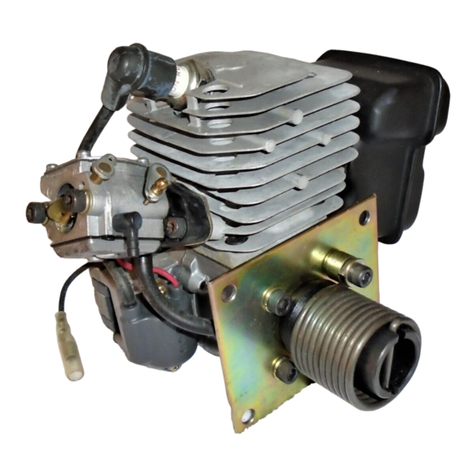
The engine F 33 A/B (Illu . 1.1.1-1 and 1.1.1-2) of Göbler-Hirth Engine Ltd. i an air-cooled
diaphragm-controlled one-cylinder 2- troke engine.
The cylinder con i t of an aluminium alloy with wear-re i tant tread alloy. C i mounted to
crankca e through tay bolt, pulley and hexagon head nut. The cylinder head con i t of a
pecial non-melting aluminium alloy that re i t in ame temper / hardne in high
temperature . It will be crewed on cylinder-by-cylinder crew and pullie without u ing
ga ket.
The pi ton con i t of an aluminium alloy and i tighted by two pi ton ring again t cylinder
thread. The pi ton i tied with connecting rod by pi ton pin and needle bearing.
The crank haft con i t of Chromoly teel (42CrMo4) and i mounted in two ball bearing . It
concern to a manufactured crank haft.
The output drive i conical and equipped with centric external thread for mounting a junction
cone on output drive. The connecting rod i connected with/ linked to the crank haft through a
crankpin and a needle bearing.
The crankca e con i t of an aluminium alloy. It i con tructed a an radial divided ca e and
con i t of ignition part and an output driving part.
Six cylinder crew with locking ring tie it. It pick up the tator plate of the ignition y tem,
on the ide of ignition.
Illustration 1.1.1-1 (Engine F 33 A)
Stand: 02.02.05 DOC_F33_B_E_0.01

GH F33 BDA
Illustration 1.1.1-2 (Engine F 33 B)
1.1.2 Description of the fuel mixture s stem
1.1.2-1 Variable jet carburettor
The fuel mixture y tem (Illu . 1.1.2-1) of the engine F 33 A con i t of a variable jet
carburettor. The carburettor i linked with intake window and the inlet diaphragm of
crankca e by a rubber flange. On thi occa ion the rubber flange i crewed with cylinder
crew and locking di c and the carburettor i tightened by a clamp in the rubber flange.
On the inlet ide of carburettor i po itioned a dry air filter which i tightened on the
carburettor by a clamp.
Illustration 1.1.2-1 (Fuel mixture y tem with variable jet carburettor)
Stand: 02.02.05 DOC_F33_B_E_0.01

GH F33 BDA
1.1.2.2 Diaphragm carburettor
The fuel mixture y tem (picture 1.1.2-2) of the engine F33 B con i t of a diaphragm
carburettor. The carburettor i linked with intake window and the inlet diaphragm of
crankca e by an aluminium flange. In thi occa ion the aluminium flange i crewed by
cylinder crew and locking di c at the cylinder and the carburettor i fixed at the aluminium
flange by in ulated part. On the inlet ide of carburettor i po itioned a dry air filter which i
tightened on the carburettor by a clamp.
Illustration 1.1.2-2 (Fuel mixture y tem with diaphragm carburettor)
1.1.3 Description of the ignition s stem
The ignition y tem (Illu . 1.1.3-1, 1.1.3-2) i available a ingle and dual ignition. It con i t
of tator plate, flywheel, one ignition coil for ingle ignition, two ignition coil for dual
ignition and ignition cable with park plug connector . The ignition y tem i all electronic.
Generator power at 50 W i available on reque t.
The tator plate i crewed with the crankca e on the ignition ide. The flywheel i located on
the crank haft and urround tator plate.
Intermediate ca e cover the flywheel of the ignition y tem. Ignition coil i / ignition coil
are po itioned at the crankca e.
Illustration 1.1.3-1 (Single ignition y tem)
Stand: 02.02.05 DOC_F33_B_E_0.01

GH F33 BDA
Illustration 1.1.3-2 (Dual ignition lighting y tem)
1.2 Installation
1.2.1 Engine installation
The four thread (M 8) for engine mounting at engine F33 A (Illu . 1.2.1-1) are po itioned at
bottom ide of crankca e.
Illustration 1.2.1-1 (Attachment thread )
The engine mounting hould be conditioned in that way, that tran ferred impul e from the
engine to the mounting will be taken over a high / wide a po ible.
Stand: 02.02.05 DOC_F33_B_E_0.01

GH F33 BDA
The damping of the mounting hould be cho en a hard a po ible, becau e engine could
way/ wing it elf with damped mounting which i too mooth. Thi lead to problem with
the fuel mixture (i.e. foam up of the fuel, uncontrolled centrifuge of the fuel pump diaphragm)
and o to an un afe running of the engine.
-Recommendation for fixing:
Engine i mounted on a tabile fixing plate that i nearly doubled a the bottom ide of the
engine (the bigger the better). At the two exterior of the fixing plate there will be fixed, in
axial way, four hard rubber damping element (on each ide two element .
Thi complete ba e will be fixed by the e rubber damping element on an according ground
plate that i connected trong with the in trument.
1.2.2 Air suppl of the engine
The engine ha to be in talled in that way, that the upplied fre h air i ufficient for cooling
and for the carburettor.
For an enclo ed in tallation it ha to be en ured that hot exhau ted cooling air i not upplied
to carburettor, becau e thi lead to dra tic reduction of power.
Al o it ha to be en ured that hot exhau ted cooling air could e cape from ca e without
ob truction, becau e thi lead automatically to an overheat of the engine and o to de truction
of it elf.
Sufficient fresh air suppl has to be attended.
1.2.3 Fuel suppl of the engine
1.2.3-1 F 33 A
The fuel upply of the engine i upported by a diaphragm pump (Illu . 1.2.3-1), which
pu hed through crank ca e low pre ure.
Illustration 1.2.3-1 (Diaphragm Fuel pump)
Thi diaphragm pump i ituated in ide fuel line between the fuel tank and carburettor. A fuel
filter alway hould be mounted between the diaphragm pump and fuel tank.
The diaphragm pump i tied at crankca e.
Stand: 02.02.05 DOC_F33_B_E_0.01

GH F33 BDA
Pay attention that in tanding po ition of the diaphragm pump the outlet i at the top. Place
fuel connecting piece i perceptible by marking (→)on the ca e.
The centrically connection the diaphragm pump i an impul e connection. The impul e line
from the crankca e to the diaphragm pump hould be a hort a po ible. For election of
impul e and fuel line it hould be noticed that inflexible line that will not extend under
pre ure hould be u ed. Impul e line hould have a maximum length of 150 mm and not
exceed a minimum in ide diameter of 6 mm.
In every ca e it i advantageou if fuel tank i po itioned above the engine, a o there i
guaranteed ome pre ure of the fuel upply. The u e of diaphragm pump i recommended
additionally. A uitable mea ure in trument hould control fuel pre ure in any ca e.
For in tallation of fuel tank below the engine, the following geometrical date hould be
noted.
The maximum length intake manifold between fuel tank and diaphragm pump hould not
exceed 2000 mm at a minimum in ide diameter of 6 mm. At thi a altitude of 1 m ha not to
exceed. During the running the po ible inclination of complete equipment ha to be
con idered (a cent / down fly of fly equipment , uphill/ downhill with ground equipment ,
….)
The maximum length of the pre ure line hould not exceed 500 mm at in ide diameter of 6
mm. At thi a maximum pre ure altitude between diaphragm pump center and floater ca e
center of the carburettor hould not be exceed.
If diaphragm pump hould be in talled at engine, it hould be mounted thi way that
diaphragm i vertical to crank haft axle (wear or ignition ide). Herewith it i guaranteed that
vibration at crank haft axle due to the engine not impair the action and function of the
diaphragm pump due uperimpo ition of the vibration .
1.2.3-2 F 33 B
The fuel upply of engine F 33 B i completely provided by diaphragm carburettor. In ide the
carburettor i integrated a diaphragm pump that provide carburettor with ufficient fuel every
time.
The diaphragm pump that i integrated in the ca e of diaphragm carburettor i connected with
the crankca e by a connecting ho e and o with pre ure pul ation of the engine. Becau e of
the exi ting pul ation, fuel i ucked from the fuel tank through a fuel filter. The carburettor
extract the needed volume of fuel that i provided by diaphragm pump concerning the
adju ted idle and load. The re t i pumped back by a return line into fuel tank.
1.2.4 Carburettor control
The throttle lide control of variable jet a well a diaphragm carburettor i handled by
bowden cable . At idle running (throttle lide i eated on crew for idle; crew for idle of idle
top throttle trike again t idle top) bowden cable hould have ome pace o that throttle
lide can reach idle po ition ecured.
At full throttle the lide ha to relea e the whole cro ection of carburettor
1.2.5 Adjustment of idle speed
Adju tment of idle peed hould be done with warm engine. If engine run up, adju t the
wanted idle peed by twi ting the crew for idle. Twi ting clockwi e ri e idle peed, twi ting
anti-clockwi e reduce idle peed. Screw for idle i fixed through a pring that prevent
unde irable wrench of the adju ting crew.
Stand: 02.02.05 DOC_F33_B_E_0.01

GH F33 BDA
1.2.6 Adjustment of the idle fuel mixture
Screw for idle i adju ted by Göbler Hirthmotoren before delivery of the engine and hould
not be twi ted. A tandard the crew i opened with 1,5 rotation .
For readju ting the crew, tie it clockwi e till crew i tight/ fixed (only tie light again t
re i tance) then turn off the crew anti-clockwi e with 1,5 rotation .
1.2.7 Fixation of plug socket at hanging installation
If engine i in talled at hanging po ition, plug ocket( ) hould be fixed that way, that drop off
or interruption of contact due to engine vibration are prevented effectively (ba ed or ecured
due to wire or omething imilar)
1.2.8 Cut off of the ignition s stem
Single Ignition:
The interrupter of the ignition y tem ha to be lay on ground (e.g. ca e) due to a witch. With
connection to the ground, the ignition y tem will be cut off.
Double Ignition:
Both interrupter ab olutely have to lay on eparate ground witcher . Thi in truction ha to
be fulfilled ab olutely, becau e if both ground cable will be laid together, one ignition circuit
can break down. With connection to the ground, the ignition y tem will be cut off.
1.3 Supervising the engine
It i trongly recommended to check the cylinder head temperature, exhau t ga temperature,
and the fuel pre ure.
The fundamental adju tment of the engine guarantee a function without problem under the
provided mounting condition . A Göbler Hirthmotoren doe not in pect the building in of the
engine, there could be given bad external condition (cooling air upply to low deep mounted
tank at climb/ go down/ up-hill/ down-hill), therefore it i e ential for a ecured engine
running to check the cylinder head-, exhau t ga temperature and the fuel pre ure.
Due to improper mounting or change at the engine without checking the cylinder head and
exhau t ga temperature, the claim of guarantee or each warranty i expired. The maximum
temperature , tated by Göbler Hirthmotoren KG, are not allowed to exceed.
The equipment mentioned in table 1.3-1 can be ordered from Göbler Hirthmotoren KG.
Table 1.3-1
De ignation Number
EGT-/CHT-Temperature-mea urement park plug 14 mm 029.33
EGT-/CHT-Temperature-mea urement park plug 10 mm 029.34
Fuel pre ure mea urement 029.20
Stand: 02.02.05 DOC_F33_B_E_0.01

GH F33 BDA
1.3.1 CHT (C linder head temperature)
Cylinder head temperature ( ee Table 1.5-1) i mea ured at fitting beneath the park plug.
Hereby a ring- haped thermocouple element i crewed in beneath the park plug. The
po itioning of the thermocouple element i very important. The connecting cable of the
thermocouple element hould be conducted upward in the way that the cooling air doe not
blow at the connection from the cable to the ring- haped mea ure element.
Only calibrated measuring equipments hould be u ed. It ha to be concerned that
ub equently lengthened mea uring cable, between thermocouple element and mea ure
in trument, could fal ify mea ured value.
Temperature measure instruments with subsequentl lengthened measuring cable
should be calibrated once more under mounting conditions.
Defective or not correct working thermocouple element , temperature indication and
mea uring cable ha to be removed immediately.
The maximum allowed c linder head temperatures indicated b Göbler-Hirthmotoren
referring to the mentioned mounting position as well as to the calibrated measure
element in this range of temperature.
1.3.2 EGT (Exhaust gas temperature)
The exhau t ga temperature ( ee Table 1.5-1) i mea ured at outlet manifold. Hereby a rod-
haped thermocouple element i clamped into a pecial ealed crewed joint. The po itioning
of the thermocouple element i very important. The thermocouple element hould be in erted
into the outlet manifold a deep a the peak of the thermocouple element i in the middle of
the outlet pipe/ tube. The gap between pi ton rim at the outlet and the mea uring peak run to
110 mm.
Only calibrated measuring equipments hould be u ed. It ha to be concerned that
ub equently lengthened mea uring cable, between thermocouple element and mea ure
in trument, could fal ify mea ured value.
Temperature measure instruments with subsequentl lengthened measuring cable
should be calibrated once more under mounting conditions.
Defective or not correct working thermocouple element , temperature indication and
mea uring cable ha to be removed immediately.
The maximum allowed exhaust gas temperatures b Göbler-Hirthmotoren referring to
the mentioned mounting position as well as to the calibrated measure element in this
range of temperature.
1.3.3 Fuel pressure
( ee table 1.5-1)
1.4 Identification plate
The identification plate i attached on ignition ide at the upper ide of the intermediate ca e.
In any ca e of problem with your engine, then apply to Göbler Hirthmotoren KG with detail
of type and erial number of engine.
Stand: 02.02.05 DOC_F33_B_E_0.01

GH F33 BDA
Illustration 1.4-1 (Identification plate po ition)
1.5 Technical data
Table 1.5-1
Manufacturer Göbler-Hirthmotoren KG
Type F 33 A
Stroke Two troke
Number of cylinder 1
Di placement 313 cm3
Stroke 69 mm
Bore 76 mm
Compre ion ratio 9,5 : 1
Performance 18 kW (24,5 HP)
RPM, max. 6500 1/min
Turn direction Left, view to PTO
Start device Recoil tarter (Option: E-Starter in combination with G 33)
Ignition y tem Electronic ignition y tem, ingle or dual
Generator 50 W, 12 V (Option)
Spark plug ingle ignition 023.22 (Hirth), B 8 HS (NGK), W 24 FS-U (N D)
Spark plug double ignition 023.26 (Hirth), C 8 HSA (NGK), U 24 FS-U (N D)
Ignition timing 16° v. TDC (at 2000 1/min)
Fuel mixture 1 Dellorto PHBE, 1 Mikuni BN34..., 1 air filter (try)
Cooling Air cooled, free air
Oil/Fuel mixture 1 : 50
Fuel 95 Octan
Two troke oil Brand two troke oil
CHT max. 280° C / 536° F
EGT max. 680° C / 1256° F
Fuel pre ure min. 0,3 bar
Engine ma 12,7 kg
Exhau t y tem ma 3,4 kg
Stand: 02.02.05 DOC_F33_B_E_0.01

GH F33 BDA
1.6 Installation sketch
Stand: 02.02.05 DOC_F33_B_E_0.01
119
230
299,5
131,5
85
M8 (4x)
74,5
209,6
380
82
90
70

GH F33 BDA
Chapter 2
Operating of the Engine
2.1 General l
The ab olute attention of thi chapter i e ential for a long, economic and ati factory
operating of the engine.
-ONLY USE BRAND 2 STROKE-OIL AND THE PRESCRIBED FUEL (MIXTURE
RATIO 1:50).
-PAY ATTENTION TO THE PRESCRIBED MIXTURE RATIO.
-REMOVE FUEL FROM THE FLOAT CHAMBERS OF THE CARBURETOR BOWLS
AND THE TANK IN CASE THAT ENGINE DOES NOT RUN FOR A LONGER
TIME. AFTER A LONGER STANDING TIME AND BEFORE START-UP ALL FUEL
RESTS SHOULD BE REMOVED FROM THE FLOAT CHAMBERS OF THE
CARBURETTOR AND FROM THE TANK.
-PAY ATTENTION THAT COOLING AND CABURETTOR ARE PROVIDED WITH
SUFFICIENT FRESH AIR.
-PAY ATTENTION, THAT HOT COOLING AIR COULD BE RUN OFF WITHOUT
OBSTRUCTION OR OTHER HINDRANCES.
-PAY ATTENTION THAT THE HOT AIR STREAM IS NOT SUCKED IN FROM THE
CARBURETTOR.
-THE IGNITION SYSTEM HAS TO RUN ONLY WITH RESISTANCE SPARK PLUGS
AND RESISTANCE SPARK PLUG CONNECTOR.
-ALWAYS ENGINE RUN/ WARM UP ITSELF.
2.2 run in recommendation
There are no pecial run in recommendation for the engine of Göbler Hirthmotoren KG
becau e the nickel- ilica alloy of the cylinder, the aluminium pi ton and the grey ca t-iron of
the pi ton ring do not have to run in one again t the other. The engine are at full throttle
from the moment of their mounting if maximum temperature meet the recommendation a
mentioned in chapter 1.
A a recommendation for an adequate run in, engine hould run at half throttle and half charge
(not more then 4000 1/min) in the fir t of five hour of running. At the fir t run there could be
a more inten ify formation of moke due to the fact that engine ha 2- troke-oil in ide it elf
(becau e of the mounting).
2.3 First Inspection
After the fir t 10 – 15 hour of running or 10 – 15 hour after big in pection the following
in pection work hould be done
-Tighten up engine fixing crew for rea on of afety.
Stand: 02.02.05 DOC_F33_B_E_0.01

GH F33 BDA
-tighten up the cylinder head crew for rea on of afety
-tighten up the park plug for rea on of afety
-viewing examination (leaking, una embled nut / crew ,…)
Attention !
It i recommended to check the following item before every engine running for rea on of
afety:
-Starter (checking of connection , fixing and condition; overhaul if nece ary)
-Carburettor (checking of connection , fixing and condition; overhaul if nece ary)
-Ignition y tem (checking connection , fixing and condition; overhaul if nece ary))
-Cylinder head (checking of fixing and condition; overhaul if nece ary)
-Cylinder (checking of fixing and condition; overhaul if nece ary )
-Outlet manifold (checking of fixing and condition; overhaul if nece ary)
-Exhau t y tem (checking of fixing and condition; overhaul if nece ary)
-Spark plug and park plug connector (checking of fixing and condition; overhaul if
nece ary)
-Fuel y tem (checking of leaking of oiled filter ; overhaul if nece ary)
2.3 Start Procedure
1. En ure fuel providing (fill tank, open fuel cock,…)
2. If engine i cold manipulate the choke. If engine i warm or hot do not manipulate the
choke. Choke lever in vertical po ition for a cold tarting (in the ca e of hand lever-choke)
3. Set throttle hand lever in idling ( lide in carburettor in idling)
4. Ignition y tem put in running (ON-po ition of the hort circuit button)
5. Start the engine (pull out the lever of the rever e tarter till re i tance i noticed, than pull
through trong and con tant; manipulate electric tarter for maximum of 10 econd than
break of 20)
6. If engine get / take throttle, the choke could be taken back (checking by little open of
them)
7. Engine ha to run warm by ¼ weight/ charge or 3000 1/min ca. 3 minute .
8. Engine ha running temperature and i ready for running.
Notice:
If engine i mounted with a centrifugal clutch, for the run up it hould be con idered the
following:
1. run up of engine in a peed range where centrifugal clutch i po itioned in fixed gearing.
Stand: 02.02.05 DOC_F33_B_E_0.01

GH F33 BDA
2. run up of engine in a peed range where centrifugal clutch i po itioned without fixed
gearing. Becau e in thi ca e the run up range i very low, the time of run up hould be
longer.
Attention !
If the warm up or other engine operation i carried out in the range where the clutch engage ,
the re ult may be increa ed wear on the urface, glazing of the coating, or overheating of the
clutch.
2.4 Operation conditions
During operation of the engine, cylinder head- and exhau t ga temperature have to be
controlled. If permi ible maximum temperature of cylinder head and/ or exhau t are not
exceed, engine can run without limit (al o full load in maximum performance). It i al o
recommended to control fuel pre ure during operation. Lack in fuel pre ure can cau e lo
in performance and et out engine.
2.5 cut off the engine
Before engine i cut off, it hould be run one minute at idle power in unencumbered tate.
Thi proceeding alway hould be noticed becau e an engine load tend to overheat when it i
cut off after highe t load.
Stand: 02.02.05 DOC_F33_B_E_0.01

GH F33 BDA
Chapter 3
Maintenance
3.1 Generall
3.1.1 Index
Thi chapter contain main in truction for technically qualified per onnel to carry out minor
in pection and repair , uch a :
-Periodical in pection of engine
-Maintenance of engine component
-Trouble hooting
3.1.2 Tools , special tools and torques
De cription and ize of tool are indicated in metrical y tem and can be purcha ed in pecial
hop .
Tools:
De cription Size De cription Size
Torque wrench 0-50 Nm Hexagon head ocket
wrench
SW 5
Engineer ’ wrench SW 10 Engineer ’ wrench SW 13
Engineer ’ wrench SW 17 Socket wrench SW 24
Screwdriver Sparkplug wrench 20.6/20.8
Special tools:
Flywheel-withdraw W 85
Pi ton ring clamp (pi ton – mounting a i tance W 108/15
Initial Torque Values
De cription Torque De cription Torque
M6 9,6-11 Nm M8 23-28 Nm
M10 45-50 Nm
3.2 Maintenance Intervals
3.2.1 Dail Inspections
Daily in pection hould be realized con cientiou before every operation. Pay attention to
following in truction :
Stand: 02.02.05 DOC_F33_B_E_0.01

GH F33 BDA
1. Air filter – checking of condition and bolting
2. Starter – checking of condition and bolting
3. Ignition component – checking of condition, mounting and junction/ connection
4. Crank ca e and cylinder – checking of leakage, condition and bolting
5. Spark plug connector – checking of condition and fit.
3.2.2 Inspection intervals
Ba ic unit a embly group In pection interval
Engine complete
Check for leak (optical) Before every operation
check for damage (optical) Before every operation
Carburettor
Clean air filter Every 50h
Check carburettor etting Every 50h
Clean carburettor All 100h
Fuel y tem
Clean fuel filter Every 50 h
Check fuel line and connection Every 25 h
Check impul e line to diaphragm pump Every 25 h
Ignition
Check ignition timing Every 100 h
Check electrode pace of park plug Every 50 h
Exhau t y tem
Check fixed po itioning and damage Every 25 h
Check exhau t lot for trace of coke Every 100 h
3.3 change of component
Part mentioned on table 3.3-1 hould be replaced after indicated running hour . If wear
appear earlier on thi part or other part of the component , replace them accordingly. Plea e
con ult Göbler Hirthmotoren KG or any authorized dealer.
Table 3.3-1
Shortening SI mean ingle ignition and hortening DI mean dual ignition.
De cription Order no. Running hour
Spark plug SI 023.22 100
Spark plug DI 023.26 100
Spark plug connector 024.22 200
Short-firing cable 026.4/380 200
Set of pi ton 014.81 1000
Crank haft F 331 A 1000
Cylinder head SI F 332 E2 1000
Cylinder head DI F 332 C3 1000
Cylinder SI / Cylinder DI F 332 D1U / F332 B1U 1000
Carburettor PHBE 34 BD/BS 1000
Air filter 066.19 100
Stand: 02.02.05 DOC_F33_B_E_0.01
Table of contents
Other Hirth Engine manuals

