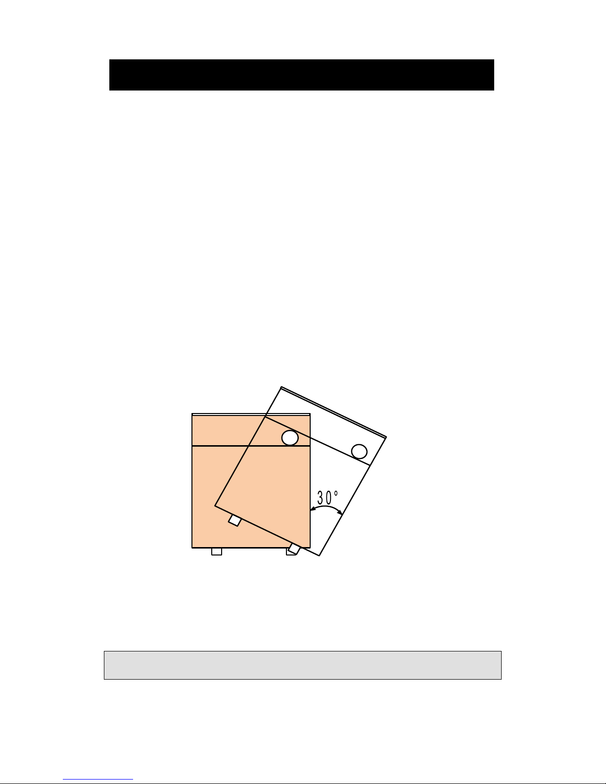
HISEER VR2002 Owner's manual

GEOTHERMAL HEAT PUMP
Installation ,Operation &Maintenance Manual VR2002
V.201212
The Installation of this unit is to adhere to all Local
Building Codes and Standards

1
Index
Pre-Installation.............................................................................................................2
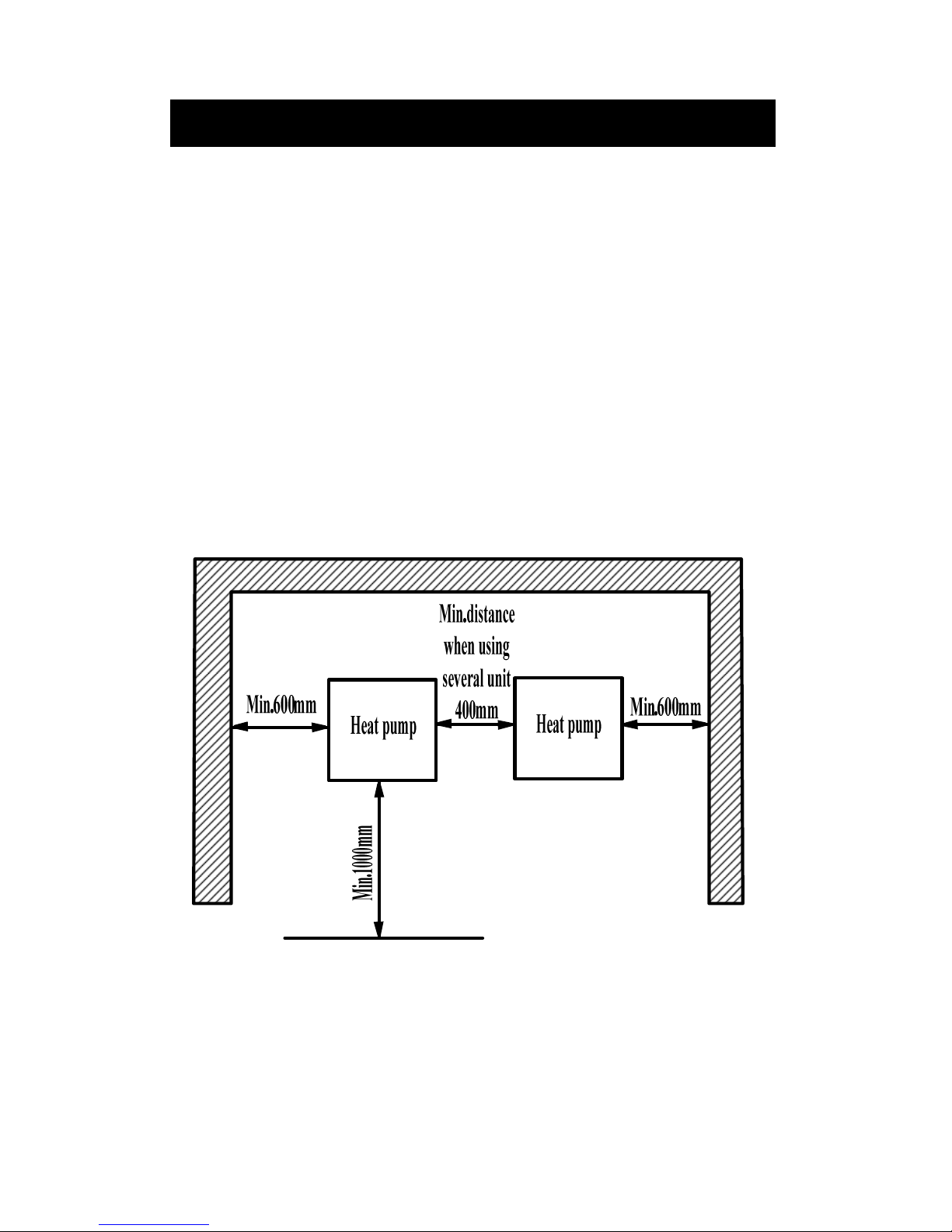
Installation Location and Positioning ........................................................................4
Buffer Tank...................................................................................................................5
System Overview Vertical Ground Loop System......................................................6
System Overview Horizontal Ground Loop System.................................................7
System Overview Ground Water with Intermediate Heat Exchanger System ......8
System Overview Floor Heating Only........................................................................9
System Overview Heating ,Cooling & Hot Water................................................... 11
System Overview Multiple Units in Series Cascade Connection...........................15
Installation ..................................................................................................................17
Electrical Connection.................................................................................................19
Controller....................................................................................................................31
Commissioning and Adjusting ..................................................................................39
Warning and alarm....................................................................................................42
Trouble shooting.........................................................................................................46
Maintenance ...............................................................................................................47
Dimension ...................................................................................................................48
Components ................................................................................................................50
Pressure drop curve ...................................................................................................56
Temperature and sensor resistance table.................................................................60
Technical specifications .............................................................................................63

2
Pre-Installation
Important Site Instructions
The installation, commissioning, inspection, maintenance and repairs must only be
carried out by a qualified person.
All electrical wiring must be completed by a licensed electrical contractor in
accordance with the appropriate standards.
The drilling work requires a permit from your local council.
The heating system and heat source must be properly designed and dimensioned
to ensure an efficient operation. It is particularly important to keep water flow
temperatures as low as possible.
The minimum heating water flow rate through the heat pump must be assured in
all operating states of the heating system.
Movement and storage
The unit must not be transported, moved or stored at greater than a 30° angle from the
upright position. Install and store the unit in a dry area. They are not rated for outdoor
use.
Safety
If a refrigerant leak occurs, remove the complete charge using a recovery unit and
store the refrigerant in mobile container.
Note: care is to be taken as the refrigerant can breakdown due to high temperature,
these refrigerants by-products are dangerous.
Once the leak has been repaired recharge the unit with the correct filling weight and
the type found on the unit’s nameplate.
Pre-Installation

3
Note: ensure the correct refrigerant gas is used to recharge the unit as an incorrect
gas can cause damage beyond repair to the compressor.
Do not use oxygen to purge lines or to pressurize a unit for any purpose.
Oxygen gas reacts violently with oil, grease and other common substances. Use only
refrigerant or dry nitrogen for testing.
Never exceed the specified maximum operating pressures.
Do not un-weld or flame cut the refrigerant lines including any refrigerant circuit
components until the entire refrigerant (liquid and vapour) has been removed from
unit. Traces of vapour should be displaced with dry nitrogen.
Refrigerant in contact with an open flame will produces toxic gases.
Ensure that the necessary safety protection equipment is available when servicing.
Have the appropriate fire extinguishers for that system.
Do not siphon refrigerant.
Avoid spilling liquid refrigerant onto the skin or splashing it into the eyes. Use safety
goggles. Wash any spills from the skin with soap and water. If liquid refrigerant enters
the eyes, immediately and abundantly flush the eyes with water and consult medical
advice.
Note: Never apply an open flame or live stream to a refrigerant container. This can
dangerously overpressure and cause an explosion.
Pre-Installation

4
Installation Location and Positioning
The unit must be installed in a protected area that is free from rain and water
penetration.
The unit must be installed on a solid level surface, preferably on a concrete pad
not connected to the main house slab foundation.
Allowances for good ventilation around the installation must be provided.
In normal operations to prevent condensation collecting on cold pipes the thermal
insulation of any cold components should be to a high level.
The unit will produce noise that is above the minimum 45 decibel rating.
Therefore the unit should be located so that it is well away from bedrooms, offices,
living areas or noise sensitive areas including neighbour’s bedrooms.
There must be suitable distances between the unit and the building to ensure
normal operation and enough room for maintenance requirements.
Installation Location and Positioning

5
Buffer Tank
A buffer tank is recommended to ensure a trouble free heat pump operation. A suitable
buffer tank can avoid excessive heat pump cycling (switching on and off).
The buffer tank provides a hydraulic separation from the volume flow in the heat
pump and heating circuits. The volume flow in the heat pump circuit remains constant,
even if the heating circuit volume flow is reduced by thermostatic valves.
If the total of the systems water volume is less than 12L/KW then a buffer tank should
be added to reduce the compressor from ON/OFF cycling. This will prolong the
compressor life span.
When a buffer tank is installed, the heating system will absorb energy from the buffer
tank first. To save energy consumption ,install the indoor pump P1 that is switched on
only when compressor is on. This is by changing EV01 to “1”.
RT sensor should be taken out of the unit and put into buffer tank’s sensor pocket. The
RT sensor is located at lower submerged sensor pocket of the plate heat exchanger.
The RT sensor in the buffer tank will control the tank temperature by starting and
stopping the compressor and pump together as required.
If RT sensor has not been changed to buffer tank’s sensor pocket when EV01 has been
changed to “1”, when the unit reaches its set temperature ,the compressor will stop,
pump P1 will also stop accordingly due to EV01 being set to “1”. When this
occurs ,there is no water circulation between the heat pump and buffer tank. RT will
keep its stopped temperature ,not the buffer tank water temperature. RT then can not
switch on compressor and pump P1 even when buffer tank water is getting cold.
Changing the RT sensor into the buffer tank will avoid this problem.
Buffer Tank

6
System Overview Vertical Ground Loop System
Name
Description Location
Name Description Location
P2 Outdoor side water
pump External OT Outdoor temperature
sensor Internal
SAK
Safety valve External FL Particle filter External
BK Brine tank/expansion
tank External
Systems Overview (Outdoor side)

7
System Overview Horizontal Ground Loop
System
Name
Description Location
Name Description Location
P2 Outdoor side water
pump External OT Outdoor temperature
sensor Internal
SAK
Safety valve External FL Particle filter External
BK Brine tank/expansion
tank External
Systems Overview (Outdoor side)

8
System Overview Ground Water with
Intermediate Heat Exchanger System
Name
Description Location
Name Description Location
P2 Outdoor side water pump
External OT Outdoor temperature
sensor Internal
P3 Ground water pump External FL Particle filter External
BK Brine tank/expansion
tank External SAK Safety valve External
FW Water flow switch External FI filter External
DP Intermediate heat
exchanger External
Principle of Operation:
An intermediate heat exchanger (DP) should be installed to prevent ground water
damaging or contaminating the unit’s internal heat exchanger. A plate heat exchanger
that is able to be cleaned is recommended for this situation that can be disassembled
for cleaning and repair or any damage plates can be replaced. Anti-freezing
measurement must be adopted to protect the ground water circuit.
Systems Overview (Outdoor side)

9
System Overview Floor Heating Only
Name
Description Location Name
Description Location
P1 Indoor side water
pump External RT Indoor side inlet water
temperature sensor Internal
EXP
Expansion tank External ST Indoor side outlet water
temperature sensor Internal
AIV
Air vent valve External STo Outdoor side outlet water
temperature sensor Internal
SAK
Safety valve External ET Exhaust gas temperature sensor
Internal
FS Automatic water
supplement valve External FL filter External
Systems Overview (Indoor side)

10
1. Heating Mode Working Principle:
a. When SF04=0,
When the RT drops below ST02-ST04, the compressor will start to heat until RT
≥
ST02+ST04. Then compressor will stop. The Compressor will start again when RT
≤
ST02-ST04.
b. When SF04=1,
ST02 is replaced by “Set temperature at heating” =ST05+ST06/10 *(ST05-OT).
Refer to page 36 “Heating compensation curve setting” and page 37 “Three curves of
different ST05 setting”
Systems Overview (Indoor side)

11
System Overview Heating ,Cooling & Hot
Water
(External water pump, three way valve and electric heater)
Name
Description Location
Name
Description Location
P1 Indoor side water pump External
RT Indoor side inlet water
temperature sensor Internal
ELK
Electric heater/boiler External
ST Indoor side outlet water
temperature sensor Internal
EXP
Expansion tank External
STo Outdoor side outlet water
temperature sensor Internal
VXV
Three way valve External
HT Hot water temperature sensor Internal
FS Automatic water
supplement valve External
ET Evaporator temperature sensor Internal
SAK
Safety valve External
FL Particle filter External
VVB
Hot water cylinder External
AIV
Air vent valve External
Systems Overview (Indoor side)

12
System Overview Heating ,Cooling & Hot Water
(External water pump, three way valve and electric heater)
1. Heating Mode Working Principle:
On heating mode, Three way valve (VXV) will open AB-A.
1.) When SF04=0:
a. When the RT drops below ST02-ST04, the compressor will start to heat until
RT≥ST02+ST04. Then compressor will stop. The Compressor will start again
when RT<ST02-ST04.
b. When the outdoor temperature meets the conditions of OT≤ST07,
the e
lectric
heater (ELK) will be activated as heating boost. It will stop heating when OT
≥ST07+ST08.
2.) When SF04=1:
ST02 is replaced by “Set temperature at heating” =ST05+ST06 *(ST05-OT). Refer
to page 36 “Heating compensation curve setting” and page 30 “Three curves of
different ST05 setting”
3.) Cooling Mode Working Principle:
On cooling mode, Three way valve (VXV) will open AB-A.
When the RT≥ST01+ST03, the compressor will start to cool until RT≤
ST01-ST03. Then compressor will stop. The Compressor will start again when
RT≥ST01+ST03.
4.) Hot water production working principle:
On hot water mode, Three way valve (VXV) will open AB-B.
When domestic hot water requirement calls, the three way revert valve (VXV) will
have the priority to revert to the hot water tank (VVB). After the domestic hot water
reach its set temperature ST09, the three way revert valve (VXV) return to its
heating/cooling position. After HT≤ST09 – ST10, three way revert valve (VXV) will
revert to hot water circuit again.
Systems Overview (Indoor side)

13
System Overview Floor Heating with Hot Water
(Internal water pump, electric heater and three way valve)
Name
Description Location Name
Description Location
P1 Indoor side water pump Internal(Option)
RT Indoor side inlet water
temperature sensor Internal
EXP
Expansion tank External ST Indoor side outlet water
temperature sensor Internal
VXV
Three way valve Internal(Option)
STo Outdoor side outlet water
temperature sensor Internal
ELK
Electric heater Internal (option)
HT Hot water temp. sensor Internal
SAK
Safety valve External ET Exhaust gas temp. sensor
Internal
FS Automatic water
supplement valve External FL Particle filter External
VVB
Hot water tank External AIV Air vent valve External
Systems Overview (Indoor side)

14
System Overview Floor Heating with Hot Water
(Internal water pump ,electric heater and three way valve)
1. Heating Mode Working Principle:
On heating mode, Three way valve (VXV) will open AB-A.
1.) When SF04=0:
a. When the RT drops below ST02-ST04, the compressor will start to heat until
RT≥ST02+ST04. Then compressor will stop. Compressor will start again
when RT≤ST02-ST04.
b. When the outdoor temperature meets the conditions of OT≤ST07,
the e
lectric
heater (ELK) will be activated as heating boost. It will stop heating when OT
≤ST07+ST08.
2.) When SF04=1:
ST02 is replaced by “Set temperature at heating” =ST05+ST06 *(ST05-OT).
Refer to page 36 “Heating compensation curve setting” and page 37 “Three
curves of different ST05 setting”
2. Hot water production working principle:
On hot water mode, Three way valve (VXV) will open AB-B.
When domestic hot water requirement calls, the three way revert valve (VXV) will
have the priority to revert to the hot water tank (VVB). After the domestic hot water
reach its set temperature ST09, the three way revert valve (VXV) return to its floor
heating position. After HT≤ST09 – ST10, three way revert valve (VXV) will revert
to hot water circuit again.
Important
The coil heat exchanger inside the hot water cylinder VVB should be well selected
to have big enough diameter and heat exchange capacity. Otherwise, heat pump
will have high outlet water temperature protection alarm AL05 frequently.
..
.
Systems Overview (Indoor side)

15
System Overview Multiple Units in Series
Cascade Connection
Name
Description Location Name
Description Location
P1 Indoor side water pump
Internal
(option) RT Indoor side inlet water
temperature sensor Internal
EXP
Expansion tank External ST Indoor side outlet water
temperature sensor Internal
SAK
Safety valve External HT Hot water temperature sensor
Internal
FS Automatic water
supplement valve External STo Outdoor side outlet water
temperature sensor Internal
CV Non-return valve External ET Exhaust gas temp. sensor Internal
FL Particle filter External VVB
Hot water cylinder External
AIV
Air vent valve External
Systems Overview (Indoor side)

16
System Overview Multiple Units in Series Cascade
Connection
(1) Heating working principle
To set two or more units in parallel operation, set the primary unit to the required
parameters, other units could have 2~5°C difference of ST01,ST02 and ST05 to allow
for energy stage control.
1. When SF04=0:
a). if the RT (inlet water temperature) is lower than ST02-ST04 of the unit, then
the unit will start to heat. The unit with the lower ST02+ST04 will stop first, the
others will stop as well if the RT continues to rise and be over its ST02+ST04.
b). RT will drop when units stop. The unit with the higher ST02-ST04 will start
first again to heat . If this unit can meet the heating capacity then its RT will not
drop any further, only this unit will run as required. If the heating load is bigger
than the capacity of one unit then the RT will continue to drop to below the second
unit ST02-ST04 , the second unit will start increasing the heating capacity.
2. When SF04=1:
ST02 is replaced by “Set temperature at heating” =ST05+ST06 *(ST05-OT).
Refer to page 36 “Heating compensation curve setting” and page 37 “Three curves
of different ST05 setting”
(2) Hot water production working principle:
On hot water mode, Three way valve (VXV) will open AB-B.
When domestic hot water requirement calls, the three way revert valve ( VXV) will
have the priority to revert to the hot water tank (VVB ). After the domestic hot water
reach its set temperature ST09, the three way revert valve ( VXV) return to heating
circuit position. After HT<ST09 – ST10, three way revert valve (VXV) will revert to
hot water circuit again.
Important
The coil heat exchanger inside the hot water cylinder VVB should be well selected to
have big enough diameter and heat exchange capacity. Otherwise, heat pump will have
high outlet water temperature protection alarm AL05 frequently.
..
.
Systems Overview (Indoor side)

17
Installation
Installation must be carried out in accordance with current Standards and Building
Codes.The heat pump does not come fitted with shutoff valves and these must be
fitted outside of the heat pump to facilitate future service.
Important
The pipe work must be flushed before the heat pump is connected so that any
contaminant does not damage the unit’s internal component parts.
..
.
Ground Loops:
1. When dimensioning the ground collectors, consideration must be given to the
geothermal location, type of rock, soil structure and the size of the heat pump.
2.
When installing the collector pipe ensure it rises constantly towards the heat pump
to avoid air pockets. If this is not possible install high points to vent the air. The
ground collectors must be free of all air.
3. All brine pipes that enter any rooms must be insulated against condensation. The
expansion tank (BK) must be installed as the highest point in the collector system
and on the incoming pipe before the brine pump. Note: Condensation may drip
from the expansion tank. Position the expansion tank so that it isn’t in the way of
other equipment.
4. When installing the circulation pump for the brine circuit, position the electric
connection at the 12 o’clock position to prevent ingress of condensate.
5. Ensure adequate thermal and sound insulation of all pipes routed through wall
apertures.
6. Thermally insulate pipes on the inside buildings and installed with a vapour seal.
As the temperature of the ground collector system can fall below 0°C, the fluid
must be protected against freezing down to –15°C. The details of the types of
antifreeze used are to be left near the unit for future servicing.
7. Shut-off valves should be installed as close to the heat pump as possible.
8. In the case of a connection to an open ground water system, an intermediate
frost-protected circuit must be provided, due to the risk of dirt and freezing that
could occur in the evaporator, this requires an extra exchanger.
IMPORTANT:
The recommended ground loop pipe length must be adjusted according to the local
conditions. The length of the collector pipe varies depending on the rock/soil
conditions and on the heating system, i.e. radiators or floor heating. Max length per
collector should not exceed 200m.
Installation

18
9. Where there is more than one ground loop these must be connected in parallel
with a means of adjusting the flow. For surface soil heat, the pipe should be buried
at a depth of about 1.8 meters and the distance between the hoses should be at
least 1 meter.
10. For bore holes the distance between the holes must be at least 15m.
11. Installation should be inspected before it is commissioned. The inspection must be
carried out by a suitably qualified person and should be documented. The above
applies to closed loop heating systems as well. If the heat pump is replaced the
installation must be re-inspected again.
12. After filling the brine ,check circuit pressure. The pressure should be approx 2 bar.
Minimum system pressure 1 bar, Max pressure should not be over 3 bar.
Pipe Connections (Indoor Side):
1. Pipe connections for the indoor side are located on the top of the unit.
2. Ensure all required safety devices, shut-off valves (as close to the heat pump as
possible) and particle filter are fitted.The safety valve must have a maximum 3
bar opening pressure and be installed on the water outlet.
3. An expansion vessel that is the correct size for the system must be installed.
Ensure that the diaphragms and seals of the expansion vessel including any safety
valves are suitable for the heat transfer medium.
4. The entire length of the overflow water pipe from the safety valves must be
inclined to prevent water pockets and must also be frost proof if required.
5. Thoroughly flush the heating system.
6. Carry out a leak test.
7. Operating pressure: 2 bar. Max pressure must not be over 3 bar.
Installation
IMPORTANT:
When connecting to a system with thermostats on all radiators a bypass valve
must be fitted, or some of the thermostats must be removed to ensure sufficient
flow through the heat pump.

19
Electrical Connection
Q13 Q14 Q34Q24 Q44 Q54 Q64 Q23 Q74 Q84 Y1 G0 Y2 A+ B- GND
RJ45
G0 PE D1 M D3D2 M MD4 D5 X1 GND X3X2 X4 X5GND GND +5V
X6 +24V
RS485
!
C
G
SIEMENS
RWR470.10
Terminal Assigments Terminal Assignments
G Power supply AC/DC 24 V Q13 Supply 1 (AC 24 V …230 V)
G0 Power supply ground Q14 Compressor 1
PE Saftey ground Q24 Compressor 2
Q34 Indoor water pump
X1 Inlet water temperature of indoor side Q44 Outdoor water pump
X2 Outlet water temperature of indoor side Q54 4-way valve
X3 Outdoor ambient temperature Q64 Electric heater or boiler
X4 Hot water temperature
X5 Outlet water temperature of outdoor side
Q23 Supply 2 (AC 24 V …230 V)
X6 Exhaust gas temperature/return gas
temperature Q74 Hot water pump or revert valve
GND Common reference point for analog input
Q84 Alarm
+5 V DC 5 V power output for active sensor Y1 Analog output 2, 0...10 V
+24 V DC 24 V power output for active sensor GND Common reference point
Y2 Analog output 2, 0...10 V
D1 Water flow switch
D2 Low pressure switch A+ A+ connector for RS485
D3 high pressure switch B- B- connector for RS485
D4 Air conditioner switch GND Optional for RS485 communication
D5 Hot water switch RJ45 Service interface for parameters
uploading and downloading
M Common reference point for digital input
Warning:
Electrical connections and servicing must be carried out under the supervision of a
qualified electrician.
..
.Electrical installation and wiring must be carried out in
accordance with Local Standards.
..
.
Electrical Connection
Table of contents
Other HISEER Heat Pump manuals
Popular Heat Pump manuals by other brands

Daikin
Daikin EKHHE200CV3 User, installation, and maintenance manual

Rointe
Rointe DALIS Series instruction manual

Mitsubishi Electric
Mitsubishi Electric CLIMAVENETA BRAN2 0021M Installation, user and maintenance manual

cec
cec GO'pac Series Installation and instruction manual

BSVILLAGE
BSVILLAGE AZURO Maintenance and user manual

Daikin
Daikin EDHQ011BB6V3 installation manual

Coleman
Coleman HC6B024 THRU 060 Technical guide

Genvex
Genvex PREMIUM PREHEAT 250 installation manual

ICP
ICP PHX4 owner's guide

COMFORTPOOL
COMFORTPOOL EasyHeat Series User and service manual

Enertech
Enertech CTC EcoLogic Family series Installation and Maintenance

Toshiba
Toshiba HWS-803H-E installation manual