hisky H-6 User manual

Instruction Manual
Thank you for purchasing our R/C system
Read this manual carefully before use
6-CH 2.4G Radio Control System
H-6
DIGITAL PROPORTIONAL RC SYSTEM
数字比例遥控系统

Table of Contents
1.0 Foreword
1.1 Declaration
1.2 Safety notice
1.3 Pre-flight checklist
目录
1
3
3
3
2.0 Features & specification
3.3 Wiring diagram&binding
3.2 Rear view
3.1 Front panel view
3.0 Function definition
2.3 XY7000S receiver specifications
2.2 H-6 transmitter features
3.5 Stick mode switch
3.4 Function keys in panel
3.8 LED presentation capabilitides
3.7 Battery installation
3.6 Left and Right-hand throttles
4.1 Model name
4.0 System menu
4.2 Model select
4.3 Model copy
4.5 Model type
4.6 Stick type
4.7 Throttle recalibration
4.4 Model reset
5.1 Right stick recalibration
5.0 Stick Recalibration
5.2 Left stick recalibration
6.1 Reverse switch
6.0 Helicopter menufunction
6.2 End point adjust
6.3 Sub trim
6.5 Throttle hold
6.4 Dual rate and exponential
3.9 Boot interface
2.1 H-6 specificationtransmitter
2.4 XY7000S receiver features
1.0 前言
1.1 重要声明
1.2 安全注意事项
1.3 飞行前注意事项
2.0 规格 与特性
3.3 连接线图和绑定
3.2 背面功能
3.1 正面功能
3.0 功能说明
2.3 机规格 XY7000S接收
2.2 H-6发射机特性
3.5 模式切换
3.4 面板功能
3.8 LED灯演示功能
3.7 电池安装
3.6 左右手切换
4.1 模型命名
4.0 系统菜单
4.2 模型选择
4.3 模型复制
4.5 模型类型
4.6 摇杆模式
4.7 油门中位校正
4.4 模型复位
5.1 右摇杆校正
5.0 摇杆校正
5.2 左摇杆校正
6.1 反位设置
6.0 直升机功能菜单
6.2 舵机行程量
6.3 辅助微调
6.5 油门保持
6.4 舵量 大小
3.9 开机界面
2.1 H-6发射机规格
2.4 接收机特性 XY7000S
4
4
4
4
5
5
6
6
7
7
9
10
10
11
11
11
12
12
13
13
14
15
17
17
18
18
19
33
33
33
34
34
34
34
35
35
36
36
37
37
39
40
40
41
41
41
42
42
42
43
44
43
46
46
47
47
48

23
H-6 Instruction Manual
Table of Contents 目录
6.9 Swash mix
6.8 Pitch curve
6.10 Revolution Mix
6.11 Program mix1
6.13 Timer
6.14 Monitor
6.12 Program mix2
7.1 Reverse switch
7.0 Airplane menufunction
7.2 End point adjustment (EPA)
7.3 Sub trim
7.9 V-tail mix
7.8 Aileron mix
7.10 Aileron mix & elevator mix
7.11 Program mix
7.13 Timer
7.14 Monitor
7.12 Channel setting
7.6 Flap mix to aileron mix
7.7 Elevator mix & aileron mix
7.4 Dual rate and exponential
6.6 Gyro sence
6.7 Throttle curve
7.5 Throttle hold
1.0 Declaration
1.2 Safety notice
1.0 Foreword
1.3 Pre-flight checklist
(1) This product is designed for experienced pilots aged 14 years or older.
(2) The user should operate the radio controlled aircraft at a legal, designated field.
(3) HiSKY accepts no responsibility for damage or injury caused by mis-operation,mis-use or
mis-control after purchase.
(4) If assistance is required, please contact the distributor or our customer service
representitives.。
(1) Follow the guidelines specified in this manual
Do not modify this transmitter in any way unless specified by this manual.
(2) Safe operation
Operate this device depending on your own skill level and your health status; refrain from
using this product if you feel feeble or fatigue. Do not operate this device under the
influence of drugs or alcohol.
(3) Flying location
Despite being highly reliable and advanced products, mechanical and electronic failures
may still happen. Do not operate the model aircraft in close proximity to people and other
obstacles; refrain from flying in averse weather or at night to avoid hurting yourself or
bystanders.
(4) Humidity
This product is made of highly complicated electronic and mechanical components, keep
the product in a dry environment and avoid humidity to avoid electrical and/or mechanical
damage.
(5) Heat
Avoid heat exposure; heat may cause electronic and mechanical components to warp or
fail, do not expose this product to excessive heat to prevent failure.
(1) Ensure that the battery packs on both the transmitter and receiver/aircraft are fully
charged prior to flight
(2) Ensure that the throttle stick and the throttle trim are at their lowest positions prior to
operation.
(3) The transmitter must be turned on prior to powering on the aircraft .To end your flight,
unplug the aircraft battery before turning the transmitter off. An incorrect order of
connection or disconnection may cause the loss of control of your aircraft.
6.9 十字盘混控
6.8 螺距曲线
6.10 油门到方向混控
6.11 程式混控1
6.13 计时器
6.14 查看行程量
6.12 程式混控2
7.1 反位设置
7.0 固定翼功能菜单
7.2 舵机行程量
7.3 辅助微调
7.9 尾翼混控
7.8 副翼混控
7.10 副翼到升降混控
7.11 程式混控
7.13 计时器
7.14 查看行程量
7.12 通道设置
7.6 襟翼到副翼混控
7.7 到 混控 升降 副翼
7.4 舵量 大小
6.6 陀螺设置
6.7 油门曲线
7.5 油门保持
19
20
21
22
23
23
24
24
25
26
26
27
27
28
28
29
29
30
30
30
31
31
32
48
48
50
51
51
51
52
53
53
54
54
55
55
56
56
56
57
57
57
58
59
59
60

H-6 Instruction Manual H-6 Instruction Manual
45
2..1 H-6 transmitter specification
2.0 Features and specifications
2.2 H-6 transmitter features
2.4 XY7000S receiver features
2.3 XY7000S receiver specifications
(1) 2.4GHz FHSS technology
(2) High reception sensitivity, high resistance to interference
(1) Channels:7
(2) Frequency: 2.4GHz ISM frequency range
(3) Modulation: PCM
(4) Spread spectrum mode: FHSS
(5) Operation voltage: 4.5-5.5V
(6) Operation current: ≤30mA
(7) Net weight: 11.5g
(8) Product size: 41mm x 28mm x 14mm
3.0 Function definition
3.1 Front panel view
1
2
3
4
5
6
7
8
12
14
15
18
19
9
10
11
16
17
20
13
21
22
1
2
3
4
5
6
1. Antenna
2.Handle
3. Helicopter mode:IDLE (N/0/1)
mode:CH5 Undercarriage(N/0)
4. D/R(Aile Elve Rudd)
5. LED
6. Left stick
7.
UP
10. DOWN
11. SELECT
12. Eyelet
13. Power
14. LCD
15. Throttle hold
16. Helicopter mode:Gyro gain
mode:CH6 Flap
17. Right stick
18.
CLEAR
Airplane
Digital trim
8. Digital trim
9.
Airplane
Digital trim
19. Digital trim
20. INC
21. DEC
22.
3.2 Rear view
1.
2.
3.
4.
5. Trainer port/DSC
6. Battery case cover
Screw 1
Screw 2
Screw 3
Screw 4
(1)Channels:6
(2)Resolution:1024
(3)Frequency:2.4GHz ISM frequency range
(4)Modulation:GFSK
(5)Spread spectrum mode:FHSS
(6)Number of frequency channels:20
(7)Hopping rate:240jump/s
(8)Output power:<=20dBm
(9)Working current:<=150mA
(10)Dimensions:150mmx188mmx70mm
(11)Net weight:324g
(1)2.4G FHSS technology
(2)Work with CCPM .
(3)Digital trim
(4)Swash mix
(5)Dual gyro gain settings
(6)Sports throttle curve
(7)Customer name with10 letters and 10 memories
(8)Low power alarm
helicopters,airplanes,etc

67
3.3 Wiring diagram and binding procedure
Aileron servo
Rudder servo
Throttle servo
Elevator servo
Power
Undercarriage servo
Flap servo
Binding:
Switch on the transmitter, reduce throttle to its lowest position and make sure the alarm is off
when powering on the receiver/aircraft. Press the bind button (if applicable) until the green light
turns, solid, signaling binding success.
Caution:
While binding, place the transmitter and receiver antennas in close proximity if possible; make
sure that there are no similar devices on bind mode within approximately 10 meters. If the light
flashes after the binding procedure is complete, retry the binding procedure again until the light
turns solid.
3.4 Function keys in panel
There are 6 function keys in panel of H-6. Details below:
SELECT UP
SELECT DOWN
SELECT
CONFIRMATION
UP INC+
DOWN DEC-
CLEAR
3.5 Stick mode switch
3.6 Left and Right-hand throttles
Throttle on the left
(1)Mechanical step
MODE2
Throttle
Rudder
Elevator
Aileron
MODE4
Throttle
Rudder
Elevator
Aileron
MODE1
Throttle
Rudder
Elevator
Aileron
MODE3
Throttle
Rudder
Elevator
Aileron
Throttle on the right
There are 4 stick modes from Mode1 through Mode 4.The throttle channel is on the left with
Modes 2 and 4,and on the right with Modes 1 and 3. A configuration diagram is shown below.
Switching between left and right- handed throttle modes requires both a mechanical and
electronic switch.
To switch the throttle stick from the left column to the right (or vice versa), a mechanical modification
needs to be made: Remove the 4 screws and rear cover to expose the base plate. The photo below
shows the internal below shows the internal views of right and left throttle setup. Using a phillips
screwdriver, loosen and remove Screw A to adjust the throttle mode,then replace the "A" screws.
Potentiometer cable connection in the corresponding positions are shown below. Replace the rear
cover when the mechanical switch is completed.
H-6 Instruction Manual H-6 Instruction Manual

89
Left throttle stick
Screw A
Right throttle stick
1
2
3
4
1234
Screw A Screw A Screw A
Screw A Screw A Screw A Screw A
Screw AScrew AScrew AScrew A
Screw A Screw A Screw A Screw A
1234
3
4
2
1
(2) Electronic adjustment
3.7 Battery installation
2
4
3
1
STICK TYPE
MODEL 1
“ ”
SYSTEM
7:STK ADJ
5:MDL TYPE
6:STK TYPE 2
1
3
4
STICK TYPE
MODEL 3
3
4
2
1
STICK TYPE
MODEL 2
3
1
2
4
STICK TYPE
MODEL 4
Ensure that both the electronic and mechanical steps have been completed before
operation
From the main front panel, press both“UP”and“DOWN” buttons at the same time, then
switch on the radio to enter the “SYSTEM” menu. Use the“UP”or“DOWN”to find the 6th
“STK TYPE”, press“SELECT” to enter stick mode selection menu. Use“INC” or“DEC”
button to choose “MODE1” or “MODE3”;MODE3 or MODE4。
Caution:
The throttle stick is located on the left for modes 2 and 4 on the right for modes 1 and 3
H-6 Instruction Manual H-6 Instruction Manual
Battery installation diagram:

10 11
3.8 LED Presentation capabilities
(2) (3)(4)
(1)
(5) (6)
6.0V
HISKY
FHSS
MO1:HCP100
NOR
3.9 Boot interface
Boot interface as picture:
6.0V
HISKY
FHSS
MO1:HCP100
NOR
TX Voltage
Model name
IDLE MODE
Electronic trim Electronic trim
Electronic trim Electronic trim
In normal operation, when the LED light shows white, it means the transmitter is working
properly. If the LED is flashing and alarm audible, please check and satisfy the following
condition.
(1)
(2)
(3)
(4)
(5)
(6)
Voltage is not less than 4V.
Ensure the throttle is at the bottom position when switch on the transmitter.
Ensure the IDLE position switch is at “N” position before operation.
Ensure the TH.HOLD position switch is at “0” position before operation.
Ensure the D/R position switch is at “0” position before operation.
Ensure the GYRO position switch is at “0” position before operation.
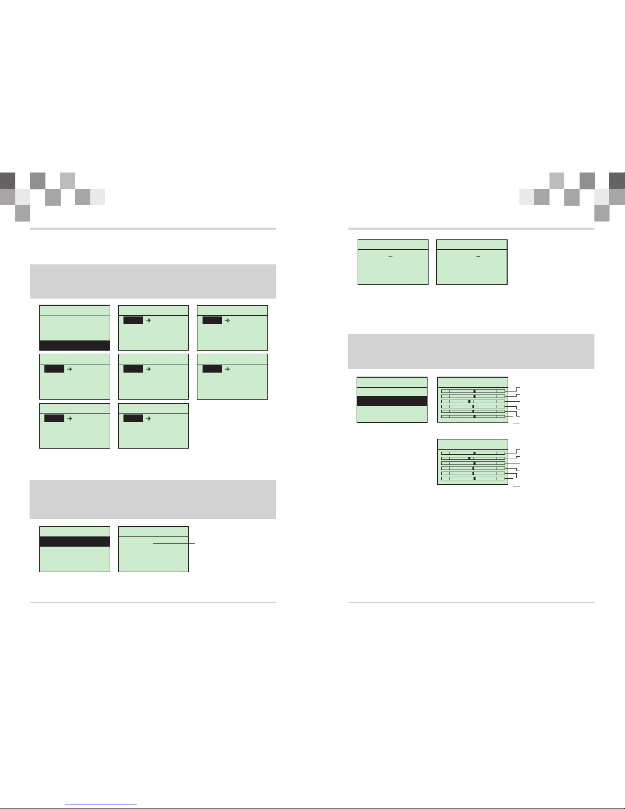
4.0 System menu
4.1 Model name
4.2 Model select
SYSTEM
2:MDL SEL
3:MDL COPY
4:MDL RST
1:MDL NAME MODEL NAME
HELI
MODEL 1 FHSS
NAME: 100HCP
This section describes the setting which are specific to the operation of the H-6 itself.
Press both and buttons at the same time, then switch on the radio to enter the
“SYSTEM” menu. Press both and buttons again to exist the “SYSTEM” menu
when setting finished.
“UP” “DOWN”
“UP” “DOWN”
In the” NAME” setting, there is a word set which is comprised of 5 bytes which you can edit or
rename the model name of your own choosing.
Press“UP”or“DOWN” to find the: , then press to enter the name
menu, press to move the cursor, press or to set the name. Press
both and buttons to exit after setting finished.
MDL NAME “SELECT”
“SELECT” “INC” “DEC”
“UP” “DOWN”
Model select:You can select each type from the HiSKY stored options, or your own custom
settings.
Press or to find the: , then press to enter the “MDL SEL”
menu, press or to choose the model type. Press both and
buttons to exit after setting finished.
“UP” “DOWN”MDL SEL “SELECT”
“INC” “DEC” “UP” “DOWN”
SYSTEM
3:MDL COPY
4:MDL RST
1:MDL NAME
2:MDL SEL
MODEL SELECT
HELI
MODEL 2 FHSS
NAME: 80HCP
MODEL SELECT
HELI
MODEL 1 FHSS
NAME: HCP100
4.3 Model copy
the function which you can copy the model type or data from one group to another.
Press or to find the , then press to enter the
“MOL COPY” menu, press or to choose the model type. Press both
and buttons to exit after setting finished.
“UP” “DOWN”“MDL COPY” “SELECT”
“INC” “DEC” “UP”
“DOWN”
H-6 Instruction Manual H-6 Instruction Manual

12 13
4.4 Model reset
MODEL RESET
HELI
MODEL 1 FHSS
DATA RESE ?
SYSTEM
1:MDL NAME
2:MDL SEL
3:MDL COPY
4:MDL RST
MODEL RESET
HELI
MODEL 1 FHSS
DATA RESE ?
4.5 Model type
NAME: HCP100 NAME: HCP100
“ ”
SYSTEM
7:STK ADJ
6:STK TYPE
5:MDL TYPE PLANE TYPE
MODEL 1
3 Servos 140
PLANE TYPE
MODEL 1
3 Servos 120
SYSTEM
4:MDL RST
1:MDL NAME
2:MDL SEL
3:MDL COPY
MODEL COPY
HELI
MODEL 1 FHSS
MODEL 3
MODEL COPY
HELI
MODEL 1 FHSS
MODEL 2
NAME: HCP100 NAME: HCP100
Reset all options to factory settings when data confusion caused by improper operation.
Press or to find the Then press“SELECT”to enter the
“MOL RST”menu, press“SELECT” to confirm the resetting.
“UP” “DOWN”“MDL RESET”,
Model types are divided into “HELICOPTER” and “AIRPLANE”. The “HELICOPTER” type may
subdivide for 90°swash plate , 120°swash plate, 140°swash plate,180°swash plate
Press“UP”or“DOWN” to find the , then press to enter the
“MOL TYPE”menu, press or to choose the model type. Press both and
buttons to exit after setting finished
“MDL TYPE” “SELECT”
“INC” “DEC” “UP”
“DOWN”
4.6 Stick type
4.7 Throttle recalibration
2
1
3
4
STICK TYPE
MODEL 3
3
1
2
4
STICK TYPE
MODEL 4
2
4
3
1
STICK TYPE
MODEL 1
3
4
2
1
STICK TYPE
MODEL 2
“ ”
SYSTEM
7:STK ADJ
5:MDL TYPE
6:STK TYPE
“ ”
SYSTEM
5:MDL TYPE
6:STK TYPE
7:STK ADJ
STICK ADJUST
Adjust stick ?
YES: INC DEC
STICK ADJUST
Adjust stick ?
YES: INC DEC
SET OK
There are 4 stick modes including MODE1, MODE2, MODE3 and MODE4.
Press“UP”or“DOWN”to find the , then press to enter the
“STY TYPE” menu, press or to choose the stick type. Press both
and buttons to exit after setting finished.
“STK TYPE ” “SELECT”
“INC” “DEC” “UP”
“DOWN”
Throttle calibration is about the throttle center position calibration.
Press“UP”or“DOWN” to find the , then press to enter the “STK ADJ”
menu, move the throttle to center position, Press both and buttons to confirm.
Press both “UP” and “DOWN” buttons to exit after setting finished
“STK ADJ” “SELECT”
“INC” “DEC”
H-6 Instruction Manual H-6 Instruction Manual

14 15
5.0 Stick Recalibration
“ ”
ENGINEER
Right Stick
Hori Axis
CENTER 0550
5.1 Right stick recalibration
Right stick recalibration
Horizontal a xis
Left
Value
Right stick recalibration
Horizontal a xis
Center
Value
“ ”
ENGINEER
Right Stick
Hori Axis
RIGHT 0870
Right stick recalibration
Horizontal a xis
Right
Value
“ ”
ENGINEER
Right stick
Hori Axis
LEFT 0230
“ ”
ENGINEER
Right Stick
DOWN 0240
Right stick recalibration
Vertical a xis
Down
Value
Axis
Stick calibration is about the stick travel and center position calibratio
Press both“SELECT”and“INC” buttons simultaneously, then switch on the radio to enter
the “ENGINEER” menu. Press both“UP”and“DOWN”buttons to exit after.
First step: push the right stick horizontally to the left end. Press both“INC”and“DEC”
buttons simultaneously to confirm, press“DOWN” to the second step.
Second step: push the right stick back to the center position. Press both and
buttons simultaneously to confirm, press “ ” to the third step
“INC” “DEC”
DOWN .
Third step: push the right stick horizontally to the right end. Press both“INC”and“DEC”
buttons simultaneously to confirm, press “DOWN” to the fourth step.
Fourth step: pull the right stick vertically down to the bottom. Press both“INC”and“DEC”
buttons simultaneously to confirm, press “DOWN” to the fifth step.
“ ”
ENGINEER
Right Stick
UP
0880
“ ”
ENGINEER
Right Stick
CENTER 0560
Right stick recalibration
Vertical a xis
Center
Value
Right stick recalibration
Vertical a xis
Up
Value
“ ”
ENGINEER
Hori Axis
LEFT 0130
5.2 Left stick recalibration
Left stick recalibration
Horizontal a xis
Left
Value
Axis
Axis
Fifth step: push the right stick back to the center position. Press both“INC”and“DEC”
buttons simultaneously to confirm, press “DOWN” to the sixth step.
Sixth step: push the right stick vertically up to the top. Press both“INC”and“DEC” buttons
simultaneously to confirm, press“DOWN” to the left stick recalibration step.
First step: push the left stick horizontally to the left end. Press both“INC”and“DEC”buttons
simultaneously to confirm, press“DOWN” to the second step.
Second step: push the left stick back to the center position. Press both“INC”and“DEC”
buttons simultaneously to confirm, press“DOWN” to the third step.
“ ”
ENGINEER
Hori Axis
CENTER 0460
Left stick recalibration
Horizontal a xis
Center
Value
H-6 Instruction Manual H-6 Instruction Manual

16 17
ENGINEER
DOWN 0130
“ ”
ENGINEER
CENTER 0450
“ ”
ENGINEER
UP 0770
Left stick recalibration
Vertical a xis
Down
Value
Left stick recalibration
Center
Value
Left stick recalibration
Vertical a xis
Up
Value
“ ”
ENGINEER
Hori Axis
RIGHT 0790
Left stick recalibration
Horizontal a xis
Right
Value
xis xisa Vertical a
Axis
Axis
Axis
Third step: push the left stick horizontally to the right end. Press both“INC”and“DEC”
buttons simultaneously to confirm, press“DOWN” to the fourth step.
Fourth step: pull the left stick vertically down to the bottom. Press both and
buttons simultaneously to confirm, press to the fifth step.
“INC” “DEC”
“DOWN”
Fifth step: push the left stick back to the center position. Press both“INC”and“DEC”
buttons simultaneously to confirm, press“DOWN” to the sixth step.
Sixth step: push the right stick vertically up to the top. Press both“INC” and“DEC”buttons
simultaneously to confirm, Press both“UP” and“DOWN” buttons to exit after setting
finished.
6.0 Helicopter Function Menu
6.0V
HISKY
FHSS
Mo1:100HFP
NOR
(2)Airplane type(1) typeHelicopter
6.0V
HISKY
FHSS
MO1:HCP100
NOR
(3)Helicopter Function Menu
Function
2:EPA
3:SUB TRIM
4:D R
1:REVERSE
6.1 Reverse switch
6.2 PAE
REVERSE
R
N
1 2 3 4 5 6
Function
2:EPA
3:SUB TRIM
4:D R
1:REVERSE
pitch
elevator throttle rudder gyro
aileron
REVERSE
R
N
1 2 3 4 5 6
Helicopter function menu manage all of the helicopter data saved in H-6. Follow step 4.5 to
enter the helicopter system setting menu, then press both“U P”and“DOWN”buttons to exit
to the function menu, as picture (1) below. Press both“U P”and“DOWN”buttons
simultaneously again to enter the helicopter function menu, as picture (3) below.
Reverse switch:If the actual output direction opposes the desired with the instruction, this
setting can correct it
Press both and buttons to enter the helicopter function menu, find the
“REVERSE” and press the“SELECT”to enter the “REVERSE” menu. Press“SELECT”to
move the cursor to select the option will be reversed. Then press“DEC”or“INC” to select
R/N. Press both“UP”and“DOWN”buttons to exit when setting finished.
“UP” “DOWN”
E is the master control of how much the transmitter will let a servo move. It’s
the master 'throw' adjustment for the channe
nd point adjust
RUDD R85 R85
EPA
AILE R100
ELEV U100
THRO U100
L100
D100
D100
EPA
GYRO H100
PIT H85 L100
L85
4:D R
Function
2:EPA
3:SUB TRIM
1:REVERSE
4:D R
Press both“UP”and“DOWN”buttons to enter the helicopter function menu, find the
“TRAVEL” and press the“SELECT”to enter the “TRAVEL” menu. Press “SELECT”to move
the cursor.Then press“DEC”or“INC”to set the data. Press both“UP”and“DOWN”
buttons to exit when setting finished.
H-6 Instruction Manual H-6 Instruction Manual

18 19
Function
2:EPA
3:SUB TRIM
4:D R
1:REVERSE SUB TRIM
AILE 0
ELEV 0
THRO 0
RUDD 0
SUB TRIM
GYRO 0
PIT 0
6.3 Sub trim
6.4 (D/R)Dual rate and exponential
Function
2:EPA
3:SUB TRIM
4:D R
1:REVERSE
(2) D/R switch at the "1" position
RUDD0
D R
E:0
DR:100
ELEV0
D R
E:0
DR:100
AILE0
D R
E:0
DR:100
AILE0
D R
E:0
DR:70
ELEV0
D R
E:0
DR:70
RUDD0
D R
E:0
DR:70
(1) D/R switch at the "0" position
This is a trim function on many computer radios, allowing trim function during set-up, and still
allowing the full trim function in flight, the factory default data is “0”.
Press both and buttons to enter the helicopter function menu, find the
“SUB TRIM” and press the to enter the “SUB TRIM” menu. Press to
move the cursor. Then press or to set the data. Press both and
buttons to exit when setting finished.
“UP” “DOWN”
“SELECT” “SELECT”
“DEC” “INC” “UP” “DOWN”
D/R is a switch that can make controls more or less sensitive. When the D/R position switch at
the “0” position, servos move 100%; when the D/R position switch at the “1” position, servos
move 70%.
Press both and buttons to enter the helicopter function menu, find the “D/R”
and press the to enter the “D/R” menu. Press to move the cursor.
Then press or to set the data. Press both and buttons to
exit when setting finished.
“UP” “DOWN”
“SELECT” “SELECT”
“DEC” “INC” “UP” “DOWN”
6.6 Gyro gain
6.5 Throttle hold
Function
6:GYRO SEN
7:TH CURV
8:PIT CURV
5:TH HOLD POS:0
Throttle hold: function which locks the throttle at a fixed point while a switch is activated.
When the “TH HOLD” position switch at the “0” position, the throttle is in a normal operation;
when the TH HOLD position switch at the “1” position, the throttle is hold in an idle.
A
Press both“UP”and“DOWN”buttons to enter the helicopter function menu, find the
“TH. HOLD” and press the“SELECT”to enter the “TH. HOLD” menu. Then press“DEC”
or “DOWN”to set the data. Press both “UP”and“DOWN”buttons to exit when setting
finished.
Gyro gain:Used to activate each rate of a dual rate gyro based on switch position. The factory
default data is “50”.
Press both and buttons to enter the helicopter function menu, find the
“GYRO SEN” and press the to enter the “GYRO SEN” menu. Press
to move the cursor. Then press or to set the data. Press both and
buttons to exit when setting finished.
“UP” “DOWN”
“SELECT” “SELECT”
“DEC” “INC” “UP”
“DOWN”
Function
6:GYRO SEN
7:TH CURV
8:PIT CURV
5:TH HOLD GYRO SENCE
50 POS0
50 POS1
H-6 Instruction Manual H-6 Instruction Manual

20
21
6.7 Throttle curve
(1) Normal mode
(2) 1 dleI mode1
Function
6:GYRO SEN
7:TH CURV
8:PIT CURV
5:TH HOLD NOR
THRO CURV
1:25
I:
O:0
0
NOR
THRO CURV
L:0
I:
O:0
0
NOR
THRO CURV
2:60
I:
O:0
0
NOR
THRO CURV
3:80
I:
O:0
0
NOR
THRO CURV
H:100
I:
O:0
0
IDLE1
THRO CURV
L:100
I:
O:0
0
IDLE1
THRO CURV
1:95
I:
O:0
0
IDLE1
THRO CURV
2:90
I:
O:0
0
IDLE1
THRO CURV
3:95
I:
O:0
0
IDLE1
THRO CURV
H:100
I:
O:0
0
Made up a 5 points, throttle operation will be adjusted by adjusting the data of each point, to
meet the modeler's specific needs.
Press both“UP”and“DOWN”buttons to enter the helicopter function menu, find the
“TH CURV” and press the“SELECT” to enter the “TH CURV” menu. Press button “SELECT”
to move the cursor. Then press“DEC”or“INC” to set the data. Press both“UP” and
“DOWN”buttons to exit when setting finished.
6.8 Pitch curve
(1) Normal mode
(3) Idle mode2
IDLE2
THRO CURV
L:0
I:
O:
0
0
IDLE2
THRO C URV
1:25
I:
O:
0
0
IDLE2
THRO CURV
2:50
I:
O:
0
0
IDLE2
THRO CURV
3:75
I:
O:
0
0
IDLE2
THRO C URV
H:100
I:
O:
0
0
(1)普通模式(NOR)
Functi on
6:GYRO SEN
7:TH CURV
8:PIT CURV
5:TH HOLD NO R
PIT C URV
L:28
I:
O:
0
0
NOR
PIT CURV
H:100
I:
O:
0
0
NOR
PIT C URV
2:48
I:
O:
0
0
NOR
PIT CURV
1:35
I:
O:
0
0
NOR
PIT C URV
3:73
I:
O:
0
0
Made up a 5 points, throttle operation will be adjusted by adjusting the data of each point, to
meet the modeler's specific needs.
Press both and buttons to enter the helicopter function menu, find the
“PIT CURV” and press the to enter the “PIT CURV” menu. Press button
to move the cursor. Then press or to set the data. Press
both and buttons to exit when setting finished.
“UP” “DOWN”
“SELECT”
“SELECT” “DEC” “INC”
“UP” “DOWN”
H-6 Instruction Manual H-6 Instruction Manual

22 23
(2) 1 Idle mode 1
IDLE1
PIT CURV
L:0
I:
O:0
0
IDLE1
PIT CURV
1:25
I:
O:0
0
IDLE1
PIT CURV
2:50
I:
O:0
0
6.9 Swash mix
Function
10:REVO MIX
11:PRO MIX1
12:PRO MIX2
9:SWASH MIX SWASH MIX
AILE 30
PIT 46
ELEV 25
:
:
: 140
(3) 2 Idle mode 2
IDLE1
PIT CURV
3:75
I:
O:0
0
IDLE1
PIT CURV
H:100
I:
O:0
0
IDLE2
PIT CURV
L:0
I:
O:0
0
IDLE2
PIT CURV
1:25
I:
O:0
0
IDLE2
PIT CURV
2:50
I:
O:0
0
IDLE2
PIT CURV
3:75
I:
O:0
0
IDLE2
PIT CURV
H:100
I:
O:0
0
Elevator
Ailerons
Pitch
Swash mix including “AILE” (ailerons), “PIT”(pitch) and “ELEV”(elevator).
Press both“UP”and“DOWN”buttons to enter the helicopter function menu, find the
“SWASH MIX” and press the“SELECT” to enter the “SWASH MIX” menu. Press button
“SELECT” to move the cursor. Then press“DEC” or“INC”to set the data, press
“CLEAR” to was reset to factory setting data. Press both“UP”and“DOWN”buttons to
exit when setting finished.
6.10 Revolution Mix
Function
10:REVO MIX
11:PRO MIX1
12:PRO MIX2
9:SWASH MIX rpm MIX
NOR IDLE
U 0 U 0
D 0 D 0
PRO MIX1
ELEV
R:U 0 D 0
SW:INH
ELEV
OFFSET:0
PRO MIX1
AILE
R:R 0 D 0
SW:INH
AILE
OFFSET:0
6.11 Program Mix 1
Function
10:REVO MIX
11:PRO MIX1
12:PRO MIX2
9:SWASH MIX PRO MIX1
AUX2
R:H 0 L 0
SW:INH
AUX2
OFFSET:0
PRO MIX1
PIT
R:H 0 L 0
SW:INH
PIT
OFFSET:0
PRO MIX1
GYRO
R:H 0 D 0
SW:INH
GYRO
OFFSET:0
PRO MIX1
RUDD
R:R 0 D 0
SW:INH
RUDD
OFFSET:0
PRO MIX1
THRO
R:U 0 D 0
SW:INH
THRO
OFFSET:0
The function of the radio which mixes throttle to rudder, preventing unwanted yaw of the
helicopter during sudden throttle increase or decrease.
Press both“UP”and“DOWN” buttons to enter the helicopter function menu, find the
“REVO MIX” and press the“SELECT” to enter the “REVO MIX” menu. Press button
“SELECT”to move the cursor. Then press“DEC” or“INC” to set the data. Press both
“UP” and“DOWN” buttons to exit when setting finished.
Used to cause specific servo responses to specific inputs separate from the basic control
set-ups.
Press both“UP”and“DOWN” buttons to enter the helicopter function menu, find the
“PRO MIX1” and press the“SELECT”to enter the “REVO MIX1” menu. Press button
“SELECT”to move the cursor. Then press “DEC” or“INC”to set the data. Press
both“UP”and“DOWN”buttons to exit when setting finished.
H-6 Instruction Manual H-6 Instruction Manual
24 25
6.12 Program Mix 2
Function
10:REVO MIX
11:PRO MIX1
12:PRO MIX2
9:SWASH MIX PRO MIX2
AUX2
R:H 0 L 0
SW:INH
AUX2
OFFSET:0
PRO MIX2
PIT
R:H 0 L 0
SW:INH
PIT
OFFSET:0
PRO MIX2
GYRO
R:H 0 D 0
SW:INH
GYRO
OFFSET:0
PRO MIX2
RUDD
R:R 0 D 0
SW:INH
RUDD
OFFSET:0
PRO MIX2
THRO
R:U 0 D 0
SW:INH
THRO
OFFSET:0
PRO MIX2
ELEV
R:U 0 D 0
SW:INH
ELEV
OFFSET:0
PRO MIX2
AILE
R:R 0 D 0
SW:INH
AILE
OFFSET:0
6.13 Timer
Function
14:MONITOR
13:TIMER TIMER
INH
10:00 off
Used to cause specific servo responses to specific inputs separate from the basic control
set-ups.
Press both“UP”and“DOWN” buttons to enter the helicopter function menu, find the
“PRO MIX2” and press the“SELECT” to enter the “PRO MIX2” menu. Press button
“SELECT”to move the cursor. Then press “DEC”or “INC”to set the data. Press
both“UP” and“DOWN”buttons to exit when setting finished.
.Timer: for setting the flight time
Press both“UP”and“DOWN”buttons to enter the helicopter function menu, find the
“TIMER” and press the“SELECT”to enter the “TIMER” menu. Press button “SELECT”
to move the cursor. Then press“DEC”or“INC” to set the data. Press both“UP”and
“DOWN” buttons to exit when setting finished.Back to the boot interface press“INC”
to start timing press“INC” to pause.,
6.14 Monitor
Function
14:MONITOR
13:TIMER
TIMER
UP T
10:00
TIMER
DOWN T
10:00
MONITOR Ailerons
Throttle
Elevator
Rudder
Gyro
Pitch
Left throttle
MONITOR Ailerons
Elevator
Throttle
Rudder
Gyro
Pitch
Right throttle
UP-T:
DOWN-T:
count from 00:00 to 10:00
count from 10:00 to 00:00
Monitor: for checking the travel data of each channel.
Press both“UP”and“DOWN”buttons to enter the helicopter function menu, find the
“MONITOR” and press the“SELECT”to enter the “MONITOR” menu. when you operate
the stick, the channel will be changed accordingly. Press both“UP”and“DOWN”buttons
to exit when setting finished.
H-6 Instruction Manual H-6 Instruction Manual

26 27
7.0 Airplane menufunction
6.0V
HISKY
FHSS
MO1:100HFP
NOR
(2)Airplane type(1) typeHelicopter
6.0V
HISKY
FHSS
Mo1:100HCP
NOR
(3)Airplane Function Menu
Function
2:EPA
3:SUB TRIM
4:D R
1:REVERSE
7.1 Reverse switch
7.2 End point adjustment (EPA)
REVERSE
R
N
1 2 3 4 5 6
Function
2:EPA
3:SUB TRIM
4:D R
1:REVERSE
aileron throttle rudder flaps
landing gear
REVERSE
R
N
1 2 3 4 5 6
Airplane Airplane
Airplane
Airplane
function menu manages all of the data saved in the H-6. Follow the step 4.5
to enter the system setting menu, then press both“UP”and“DOWN” buttons to exit
to the function menu, as picture (2) below. Press both“UP”and“DOWN”buttons
simultaneously again to enter the function menu, as picture (3) below.
Reverse switch:If the actual output direction opposites the desired output, this setting can
reverse the direction of travel.
Press both“UP”and“DOWN” buttons to enter the airplane function menu, find the
“REVERSE” and press the“SELECT”to enter the “REVERSE” menu. Press“SELECT”to
move the cursor to select the option will be reversed. Then press“DEC”or“INC” to select
R/N. Press both“UP”and“DOWN”buttons to exit when setting finished.
E is the master control of how much the H-6 will let the servo or channel
move. It’s the master 'throw' adjustment for the channel.
nd point adjusment
Press both“UP”and“DOWN”buttons to enter the Airplane function menu, find the “TRAVEL”
and press the“SELECT”to enter the “TRAVEL” menu. Press“SELECT”to move the cursor.
Then press“DEC”or“INC”to set the data. Press both“UP”and“DOWN”buttons to exit
when setting finished.
Function
2:EPA
3:SUB TRIM
1:REVERSE
4:D R
SUB TRIM
AILE 0
ELEV 0
THRO 0
RUDD 0
SUB TRIM
GYRO 0
PIT 0
7.3 Sub trim
RUDD R85 R85
EPA
AILE R100
ELEV U100
THRO U100
L100
D100
D100
EPA
GYRO H100
PIT H85 L100
L85
7.4 (D/R)Dual rate and exponential
RUDD0
D R
E:0
DR:100
ELEV0
D R
E:0
DR:100
AILE0
D R
E:0
DR:100
(1) D/R switch at the "0" position
Function
2:EPA
3:SUB TRIM
4:D R
1:REVERSE
4:D R
Function
2:EPA
3:SUB TRIM
1:REVERSE
4:D R
This is a trim function on many computer radios, allowing trim function during set-up, and still
allowing the full trim function in flight, the factory default data is “0”.
Press both“UP”and“DOWN”buttons to enter the Airplane function menu, find the
“SUB TRIM” and press the“SELECT”to enter the “SUB TRIM” menu. Press“SELECT”to
move the cursor.Then press“DEC”or“INC”to set the data. Press both“UP”and“DOWN”
buttons to exit when setting finished.
D/R is a switch that can make controls more or less sensitive. When the D/R position switch at
the “0” position, servos moves within 100% of its physical limit; when the D/R position switch
at the “1” position, servos has within 70% travel.
Press both and buttons to enter the Airplane function menu, find the “D/R”
and press the to enter the “D/R” menu. Press to move the cursor.
Then press or to set the data. Press both and buttons to exit
when finished with the setup.
“UP” “DOWN”
“SELECT” “SELECT”
“DEC” “INC” “UP” “DOWN”
H-6 Instruction Manual H-6 Instruction Manual
elevator

28 29
(2) D/R switch at the "1" position
AILE0
D R
E:0
DR:70
ELEV0
D R
E:0
DR:70
RUDD0
D R
E:0
DR:70
7.6 Flap Mix to Aileron Mix
(1)
FLAP AILE
AI1R
AI2R 100L
FLAP1 100
FLAP2 100
100
100
:
:
100L
INH
OFF
(2)
FLAP AILE
AI1R
AL2R 100L
FLAR1 100
FLAR2 100
100
100
:
:
100L
MIX
ON
(3)
7.5 Throttle hold
POS:0
Function
5:TH HOLD
6:FLAP-AILE
7:ELEVRON
8:AILE DIFF
Function
5:TH HOLD
6:FLAP-AILE
7:ELEVRON
8:AILE DIFF
Throttle hold: function which locks the throttle at a fixed point while a switch is activated.
When the “TH HOLD” position switch at the “0” position, the throttle is in a normal operation;
when the TH HOLD position switch at the “1” position, the throttle is hold in an idle.
A
Press both and buttons to enter the airplane function menu, find the
“TH. HOLD”and press the to enter the “TH. HOLD” menu. Then press or
to set the data. Press both and buttons to exit when setting finished.
“UP” “DOWN”
“SELECT” “DEC”
“DOWN” “UP” “DOWN”
This function permits mixing of the aileron and flag channels.
Press both and buttons to enter the airplane function menu, find the
“FLAG-AILE” and press the“SELECT”to enter the “FLAG-AILE” menu. Press button
“SELECT”to move the cursor. Then press“DEC”or“INC” to set the data. Press both
“UP”and“DOWN”buttons to exit when setting finished.
“UP” “DOWN”
AI1 refer to aileron 1,AI2R refer to aileron 2. Flap Mix to Aileron Mix function off shown as Fig.
(2), Flap Mix to Aileron Mix function on shown as Fig.(3)
R
7.8 Aileron mix
(1)(3)
(2)
AILE DIFF
AILE1
100
AILE2 100
100
:
100
INH
: AILE DIFF
AILE1
100
AILE2 100
100
:
100
MIX
:
OFF ON
7.7 oElevator mix t aileron mix
(1)
ELEVRON
AI1R
AL2R 100L
ELEV1 100
ELEV2 100
100
100
:
:
100L
MIX
(3)
ELEVRON
AI1R
AI2R 100L
ELEV1 100
ELEV2 100
100
100
:
:
100L
INH
(2)OFF ON
Function
5:TH HOLD
6:FLAP-AILE
7:ELEVRON
8:AILE DIFF
Function
5:TH HOLD
6:FLAP-AILE
7:ELEVRON
8:AILE DIFF
This function permits mixing of the elevator and aileron channels.
Press both“UP”and“DOWN”buttons to enter the airplane function menu, find the
“ELEVATOR” and press the“SELECT”to enter the “ELEVATOR” menu. Press button
“SELECT”to move the cursor. Then press“DEC”or“INC”to set the data. Press both
“UP”and“DOWN”buttons to exit when setting finished.
AI1 refer to aileron 1,AI2R refer to aileron 2. Elevator mix t aileron mix function off shown
as Fig.(2), Elevator mix t aileron mix function on shown as Fig.(3)
R o
o
This function permits mixing of the aileron channel.
Press both“UP”and“DOWN”buttons to enter the airplane function menu, find the
“AILE DIFF” and press the“SELECT”to enter the “AILE DIFF” menu. Press button
“SELECT” to move the cursor. Then press“DEC”or“INC” to set the data. Press both
“UP”and“DOWN”buttons to exit when setting finished.
Aileron mix function off shown as Fig.(2), Aileron mix function on shown as Fig.(3)
H-6 Instruction Manual H-6 Instruction Manual

30 31
7.10 Aileron mix & elevator mix
(1)(3)
(2)
ELEV2 100
ELEV1 100
:
: INH
AILEVATOR
AILE3 50
AILE4 50
:
: ELEV2 100
ELEV1 100
:
: MIX
AILEVATOR
AILE3 50
AILE4 50
:
:
7.11 Program Mix
OFF ON
7.9 V-tail mix
(1)(3)
RUDD1 50
RUDD2 50
:
: INH
(2)
V TAIL
ELEV1 50
ELEV2 50
:
: RUDD1 50
RUDD2 50
:
: MIX
V TAIL
ELEV1 50
ELEV2 50
:
:
OFF ON
Function
9:V TAIL
10:AILEVATOR
11:RP O MIX1
12:CH.SET
Function
9:V TAIL
11:PRO MIX1
12:CH.SET
10:AILEVATOR
Used on a V-tail model to have 2 servos operate 2 control surfaces as both rudder and elevator.
Press both“UP”and“DOWN”buttons to enter the airplane function menu, find the
“V-TAIL” and press the“SELECT”to enter the “V-TAIL” menu. Press button“SELECT”
to move the cursor. Then press“DEC” or“INC”to set the data. Press both“UP” and
“DOWN” buttons to exit when setting finished.
V-tail V-tail mix function off shown as Fig.(2), mix function on shown as Fig.(3)
This function permits mixing of the aileron and elevator channels.
AILEVATO AILEVATO
Press both“UP”and“DOWN” buttons to enter the airplane function menu, find the
“ ” and press the“SELECT”to enter the “ ” menu. Press button
“SELECT”to move the cursor. Then press“DEC”or“INC”to set the data. Press both
“UP”and“DOWN”buttons to exit when setting finished.
Aileron mix & elevator mix function off shown as Fig.(2), Aileron mix & elevator mix function
on shown as Fig.(3)
Used to cause specific servo responses to specific inputs separate from the basic
control set-ups.
Press both“UP”and“DOWN” buttons to enter the Airplane function menu, find the
“PRO MIX1” and press the“SELECT” to enter the “PRO MIX1” menu. Press button
“SELECT”to move the cursor. Then press“DEC” or“INC”to set the data. Press
both“UP”and“DOWN”buttons to exit when setting finished.
PRO MIX1
GEAR
R:H 0 D 0
SW:INH
GEAR
OFFSET:0
PRO MIX1
RUDD
R:R 0 L 0
SW:INH
RUDD
OFFSET:0
PRO MIX1
THRO
R:U 0 D 0
SW:INH
THRO
OFFSET:0
PRO MIX1
ELEV
R:U 0 D 0
SW:INH
ELEV
OFFSET:0
PRO MIX1
AILE
R:R 0 L 0
SW:INH
AILE
OFFSET:0
7.12 Channel setting
CH.SET
FLAP:GYRO
GEAR :TH.HOLD
PRO MIX1
AUX2
R:H 0 L 0
SW:INH
AUX2
OFFSET:0
PRO MIX1
FLAP
R:H 0 L 0
SW:INH
FLAP
OFFSET:0
Function
10:AILEVATOR
11:PRO MIX1
12:CH.SET
9: TAILV
Function
9:V TAIL
11:PRO MIX1
10:AILEVATOR
12:CH.SET
Press both“UP”and“DOWN”buttons to enter the Airplane function menu, find the
“ ” and press the to enter the “ ” menu. Press button
to move the cursor. Then press or to set the data. Press both and
buttons to exit when setting finished.
CH.SET “SELECT”CH.SET “SELECT”
“DEC” “INC” “UP”
“DOWN”
7.13 Timer
Timer: for setting the flight time.
Press both“UP”and“DOWN”buttons to enter the helicopter function menu, find the “TIMER”
and press the“SELECT”to enter the “TIMER” menu. Press button“SELECT”to move the
cursor. Then press“DEC” or“INC” to set the data. Press both“UP” and“DOWN” buttons
to exit when setting finished.Back to the boot interface press“INC”to start timing press
“INC” to pause.
,
H-6 Instruction Manual H-6 Instruction Manual

32 33
TIMER
UP T
10:00
TIMER
DOWN T
10:00
7.14 Monitor
Function
14:MONITOR
13:TIMER MONITOR Ailerons
Throttle
Elevator
Rudder
Flaps
Landing gear
Left throttle
MONITOR Ailerons
Elevator
Throttle
Rudder
Right throttle
Function
14:MONITOR
13:TIMER TIMER
INH
10:00 off
UP-T:
DOWN-T:
count from 00:00 to 10:00
count from 10:00 to 00:00
Monitor: for checking the travel data of each channel.
Press both and buttons to enter the Airplane function menu, find the “MONITOR”
and press the to enter the “MONITOR” menu.when you operate the stick, the
channel will be changed accordingly. Press both and buttons to exit when
setting finished.
“UP” “DOWN”
“SELECT”
“UP” “DOWN”
1.1 重要声明
1.2 安全注意事项
1.0 前言
1.3 飞行前注意事项
(1) 本产品适用于有操作模型经验者,年龄不小于14周岁的人群。
(2) 使用场所必须是当地合法的遥控飞机飞行场地。
(3) 产品一经售出,我们将不负任何由操作和使用、控制等方面产生的安全责任。
(4) 如遇使用、操作、维修等问题,我们委托经销商提供技术支持和今后服务,或联系我们的 客服。
(1) 正当使用本产品
请勿自行改装,请在产品功能允许的范围内进行操作和使用。
(2) 安全操作
请根据自身的状态和飞行技能,操作遥控模型。疲劳、精神不佳或操作不当,将会增加意外风险
的概率。
(3) 远离人群和障碍物
遥控模型飞行时具有不确定的因素,飞行时必须远离人群,建筑,高压电线等,同时不要在夜晚,
风雨,雷电等恶劣天气下使用,以确保飞行者,周围人群和财产的安全。
(4) 远离潮湿环境
本产品是由许多的机械零件和电子元件组成,必须防止潮湿或水气进入机休,以免机械零件,
电子元件故障而引发意外。
(5) 远离热源
本产品是由许多的机械零件和电子元件组成,必须远离热源,以止日晒,避免因高温引起的变
形,甚至损坏。免机械零件,电子元件故障而引发意外。
(1) 确保发射机与接收机电池电量处于饱和状态。
(2) 开机前确保油门摇杆处于最低状态。
(3) 开机时必须遵守电源开、关顺序。开机时应先开启发射机的电源,再接通飞机的电源;关机时
应先断开飞机的电源,再断开发射机的电源。不正确的开、关机会造成模型失控,影响自身和
他人的安全,请养成正确的开、关机习惯。
This device complies with part 15 of the FCC rules.
Operation is subject to the following two conditions
(1) this device may not cause harmful interference, and
(2) this device must accept any interference received, including interference that may
cause undesired operation.
Changes or modifications not expressly approved by the party respondsible for compliance
could void the user's authority to operate the equipment.
H-6 Instruction Manual H-6说明书
Flaps
Landing gear

H-6说明书 H-6说明书
34 35
2.0 规格 与特性
2.1 H-6发射机规格
2.2 H-6发射机特性
2.4 XY7000S接收机特性
2.3 XY7000S接收机规格
(1)通道: 6
(2)分辨率: 1024
(3)发射频率: 2.4GHz ISM 频段
(4)调变方式: GFSK
(5)展频模式: FHSS
(6)展频信道数: 20
(7)跳频速率: 240跳/秒
(8)发射功率: ≤20dBm
(9)工作电流: ≤150mA
(10)产品尺寸: 150mmx188mmx70mm
(11)净重: 324g
(1)采用2.4G跳频(FHSS)技术
(2)支持CCPM直升机,固定翼
(3)数字微调
(4)十字盘混控
(5)双段陀螺感度调整和快捷切换
(6)5点螺距,油门曲线
(7)10组模型数据储存
(8)低压报警
(1)通道: 7
(2)工作频率: 2.4GHz ISM 频段
(3)制式: PCM
(4)展频模式: 跳频FHSS
(5)工作电压: 4.5-5.5V
(6)工作电流: ≤30mA
(7)产品尺寸: 41mmx28mmx14mm
(8)净重: 11.5g
(1)采用2.4G跳频(FHSS)技术
(2)接收灵敏度高,抗干忧能力强
1
2
3
4
5
6
7
8
12
14
15
18
19
9
10
11
16
17
20
13
21
22
3.0 功能说明
3.2 背面功能
1
2
3
4
5
6
1. 螺丝1
2. 螺丝2
3. 螺丝3
4. 螺丝4
5. 模拟口
6. 电池盖
3.1 正面功能
1. 天线
2.
3.
把手
直升机模式:倒飞(N/0/1)
固定翼模式:CH5起落架(N/0)
4. D/R(副翼 升降 方向舵)
5. 指示灯
6. 左操纵杆
7. 数字微调
8. 数字微调
9. 上翻键
10. 下翻键
11. 选择键
12. 挂钩
13. 电源开关
14. 显示屏
15. 油门保持
16.直升机模式: 陀螺仪
固定翼模式: CH6襟翼
17. 右操纵杆
18. 数字微调
19. 数字微调
20. 加键
21. 减键
22. 复位键
.

36 37
3.3 连接线图和绑定
3.4 面板功能
H-6功能面板上有6个按键,其功能如下:
向上增加
向下减少
复位键
3.5 模式切换
3.6 左右手切换
左手油门模式
(1) 机械切换
模式2
油门
方向
升降
副翼
模式4
油门
方向
升降
副翼
模式1
油门
方向
升降
副翼
模式3
油门
方向
升降
副翼
右手油门模式
副翼舵机
方向舵机
油门舵机
升降舵机
电源
起落架舵机
襟翼舵机
绑定:开启发射机电源,油门摇杆处于最低位置,无报警状态下接通接收机电源,按住接收机上
的BIND按键,红灯闪烁后松手,直到接收机LED灯显示绿色,绑定成功。
注意:让接收机的天线尽量靠近发射机的天线,同时10米内无相同的设备进行绑定,如果接收机
的LED灯还在闪烁,设备绑定失败,请重新绑定。
选择 向上
选择 向下
选择 确认
共四种模式:左手油门包括模式2和模式4;右手油门包括模式1和模式3,如图:
如果要进行左右手切换,则要分二步才能完成,即机械切换和电子切换。
用十字螺丝批松开后壳上4个螺丝,取下后壳。左右手油门分别如下图。用十字螺丝批松开左右手
操纵杆如图所示螺丝A,将油门操纵与非油门操纵对调,如左右手油门操纵图所示,再将螺丝A拧
紧。电位器的连接线如图所示(1,2,3,4)。完成后安装好后壳。
H-6说明书 H-6说明书
Table of contents


