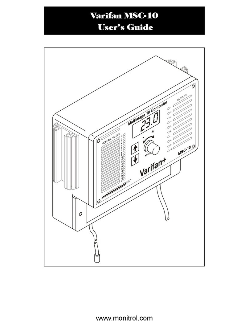
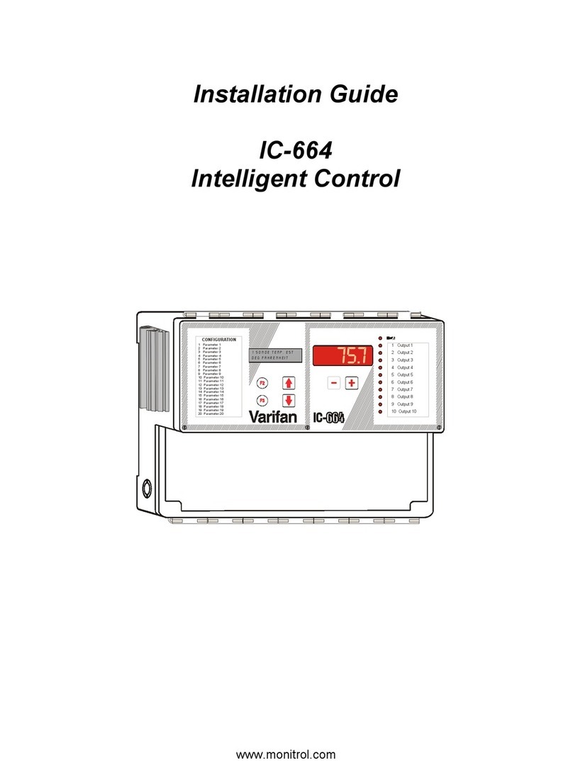
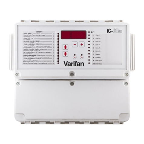
Varifan IC-610 User manual

IC-610
USER’S MANUAL
www.monitrol.com

Page 2
IC-610 - Intelligent Control
Although the manufacturer has made every effort
to ensure the accuracy of the information
contained herein, this document is subject to
change without notice due to ongoing product
development.
WARNINGS AND PRECAUTIONS
Equipment, probe failure, blown fuses and/or
tripped breakers may prove harmful to the
contents of the building. Therefore it is strongly
recommended to install backup devices and alarm
or warning devices. Spare equipment should also
be available at the owner’s site. Equipment
manufactured by the manufacturer is protected
against normal line surges. High surges caused
by thunder storms or power supply equipment
may damage this equipment. For added security
against line voltage surges it is recommended that
surge and noise suppression devices be installed
at the electrical distribution panel. Use of shielded
cable for probes is recommended for protection
against lightning. These devices are available
from most electrical supply distributors.
RECOMMENDATIONS
The manufacturer recommends that all installation
procedures described herein be performed by a
qualified electrician or installation technician.
Further more the manufacturer recommends to
test all the functions and equipment connected to
the IC, including the alarm system and backup
devices, after installation, after changes to the
installation and every month after that.
Fuse verification and replacement, as well as the
proper setting of control values shall be the
responsibility of the owner of this equipment.
www.monitrol.com

Page 3
TABLE OF CONTENTS
TABLE OF CONTENTS
WARNINGS AND PRECAUTIONS
CHAPTER 1 - INTRODUCTION
1. General ........................................................................... 5
1.1 Description....................................................................... 5
1.1.1 Compatible Modules........................................................ 6
1.1.2 Other Features ................................................................ 7
1.1.3 Configurations ................................................................. 8
1.1.4 Applications ..................................................................... 8
1.1.5 Control Modules .............................................................. 8
1.2 Definition of Terms .......................................................... 9
CHAPTER 2 - INSTALLATION
2.1 Unpacking....................................................................... 12
2.2 Mounting ........................................................................ 12
2.3 Connection Procedure.................................................... 13
2.3.1 Electrical Power.............................................................. 13
2.3.1.1 Line Voltage Detector Switch ......................................... 13
2.3.2 Electrical Power / 3 Phase.............................................. 15
2.3.3 Electrical Cables............................................................. 15
2.3.4 Electrical Grounding ....................................................... 15
2.3.5 Safety Control Backup.................................................... 18
2.3.6 Terminal Block Connections........................................... 18
2.4 Guidelines - Modules / Sensor Location......................... 22
2.4.1 Location of Control Modules........................................... 22
2.4.2 Inside Temperature Sensor ............................................ 22
2.4.3 Inside Temperature Average Setup................................ 22
2.4.4 Outside Temperature Sensor ......................................... 22
2.4.5 Static Pressure Sensor................................................... 22
2.4.6 Probes and Modules....................................................... 22
2.4.7 Setup .............................................................................. 23
2.5 Alarm Connections ......................................................... 23
www.monitrol.com

Page 4
IC-610 - Intelligent Control
CHAPTER 3 - USER’S GUIDE
3.1 Faceplate........................................................................ 27
3.1.1 Settings List.................................................................... 27
3.1.2 LCD Display ................................................................... 27
3.1.3 Function Buttons ............................................................ 27
3.1.4 LED Status Window ....................................................... 27
3.1.5 Setting Buttons (arrows)................................................. 27
3.1.6 Value Buttons (+ and -) .................................................. 29
3.1.7 Output Segments ........................................................... 29
3.2 Settings .......................................................................... 29
3.2.1 Time of Day .................................................................... 29
3.2.2 Growth Day .................................................................... 30
3.2.3 Ramping ......................................................................... 30
3.2.4 Probes ............................................................................ 33
3.2.5 Supervisor Mode ............................................................ 34
3.2.6 Feed and water consumption ......................................... 35
3.3 Configuration .................................................................. 36
3.3.1 Downloading a New Configuration ................................. 36
3.4 Abbreviations.................................................................. 37
FIGURES
1 Figure 1 IC-610SL Faceplate ......................................... 6
2 Mounting Position and Devices ...................................... 14
3 IC-610 Main Board (for 1059 board A, B ou C) ............. 16
4 IC-610 Main Board (for 1059 board D) .......................... 17
5 Safety Control Backup Wiring 1 ..................................... 19
6 Safety Control Backup Wiring 2 ..................................... 20
7 Typical Sensor Wiring .................................................... 21
8 Connections for an Alarm .............................................. 24
9 Connections for the Installation of a Siren...................... 24
10 Typical Ramping Curve .................................................. 31
11 Three Point Ramping Curve........................................... 33
APPENDIX
Troubleshooting.............................................................. 39
Specifications ................................................................. 41
WARRANTY .................................................................. 43
www.monitrol.com

Page 5
CHAPTER 1 - INTRODUCTION
1. GENERAL
This document provides you with the necessary
information to install and operate the IC-610 as well as the
IC-610SL (see page 6) . The information is presented as
follows:
•Introduction
•Installation
•User’s Guide
•Appendix
1.1 DESCRIPTION
Congratulations on your purchase of the IC-610 ventilation
system. You have just acquired one of the safest, most
reliable and userfriendly controls on the market. The IC-
610 provides you with full control over temperature,
humidity, pressure and heat, resulting in a comfortable
environment for your livestock.
The IC-610’s features are:
•Possibility to connect 6 sensors of the following types:
static pressure, relative humidity, potentiometer, in-out
temperature, (4-20 mA), and feed & water.
•6 ON/OFF relays
•without PM-1 - 8 var. stages (4 VSM-2) and 6 ON/OFF
stages
with PM-1 - 4 var. stages (4 fans max each) and 6 ON/
OFF stages
or 6 ON/OFF stages and 8 ON/OFF stages (CM3-2 or
CM10-2)
•Ramping (minimum speed, temperature, humidity, etc)
•High and low temperature recall
•Control & monitoring of feed and water consumption
•Alarm logic: high-low temp., power/control/probe
failure, feed & water, fan failure
•Internal alarm relay with a 8 second time delay
•Second fan compensation (prevents drastic increases
of CFM)
•Cool cell operation and air inlet control
•Fan speed display (RPM) with Smart Fans only
CHAPTER 1 - INTRODUCTION
www.monitrol.com

Page 6
IC-610 - Intelligent Control
•Time clock for feed & water consumption, lighting,
ramping ...
Enclosure: - Easy access
Hinged covers
High and low voltage components
separated
Water-resistant
1.1.1 Compatible modules
The Intelligent Control is considered a “master control
unit” and can control and monitor up to 8 of the following
modules (1 or 2 per output):
VSM-2 Variable Speed Module (max. 4), 2 variable
stages, 6 Amp. nominal each (0.1 A - 6 A)
CM10-2 Control Module, 2 single speed stages, 10
Amp. each (0.3 - 10 A)
CM3-2 Control Module, 2 on/off stages 4 Amp. each
(5 mA - 4 A)
CIM-1 Curtain, Air Inlet or 2 speed motors module
(5 mA - 4 A)
CIP-1 Curtain and Air Inlet Positioner (5 mA - 3A)
IC-610SL This slave unit specifically designed for the
IC-610 has 10 output leds. Used in
conjunction with its master, the SL gives the
operator 6 more inputs, 4 communication
ports and 6 internal relays. The IC-610SL
module basically doubles the number of
outputs.
Figure 1 IC-610SL Faceplate
www.monitrol.com

Page 7
1.1.2 Other features
The IC-610 can also monitor up to 6 sensors among the
following:
• Temperature sensor
• Humidity sensor
• Static pressure sensor
• 4 @ 20 mA
Other optional features of the IC-610:
•Manual override capability
Compatible with the SVPC-40 computer interface
www.monitrol.com

Page 8
IC-610 - Intelligent Control
1.1.3 Configurations
The IC-610 contains a microprocessor which memorizes
the operational logic programmed in the configuration
you will download. The operational logic is a software
program created for your particular configuration (ie. your
equipment and installed control modules). The
operational logic is stored inside the small configuration
module supplied with the IC-610. After the “download”,
the configuration program is stored in the main (bottom)
board. Should this board be replaced, a new download
will be required. The downloading procedure is described
later in this manual (refer to section 3.3 of this manual).
1.1.4 Applications
The IC-610 control is used for heating, cooling and
ventilation equipment in animal confinement buildings or
greenhouses. The applications where the IC-610 can be
used include the following systems:
• Multistage ventilation / heating / sprinkler systems
• Combined natural and forced ventilation systems
• Room ventilation systems
1.1.5 Control modules
The IC-610 can be integrated in a fully automated
system using its built-in program with various control
modules. Four main categories of various modules are:
ON/OFF Module:The ON/OFF module operates in an
ON/OFF switching mode using solid-
state relays (CM3-2 & CM10-2).
Actuator Module:The actuator module is used on
curtain machines and inlet actuators
which provide OPEN and CLOSE
commands.
Power Module: No special control module is required
when the IC-610 is controlling a Power
Module.
Variable Speed Module:The variable speed module controls the
speed of regular variable speed fans.
CHAPTER 1 - INTRODUCTION
www.monitrol.com

Page 9
1.2 DEFINITION OF TERMS
MAIN SET POINT
The desired room temperature. Other temperature
settings on the IC-610 are relative to the main set point
temperature.
RELATIVE SET POINT
A value added to or subtracted from the main set point
which results in a new temperature at which a desired
action starts or stops.
ROOM TEMPERATURE
The actual temperature of the room.
ROOM HUMIDITY
The actual relative humidity level of the room.
MINIMUM FAN SPEED
The desired minimum speed for variable speed fans.
RAMPING
An automatic daily reduction or addition in the main set
point and all temperature settings are relative to this.
DIFFERENTIAL
ON/OFF (relay). Range of temperature where two
conditions are possible. The output depends on whether
the temperature was increasing or decreasing when it
enters that range.
VARIABLE. (Bandwidth) Temperature range where a
variable fan speed fan accelerates, as the temperature
increase. Minimum value at relative set point and 100% at
relative set point + Bandwidth.
DRIP COOL
A device used to cool down livestock (sprinklers).
www.monitrol.com

Page 10
IC-610 - Intelligent Control
CHAPTER 2
INSTALLATION
www.monitrol.com

Page 11
www.monitrol.com

Page 12
IC-610 - Intelligent Control CHAPTER 2 - INSTALLATION
CHAPTER 2 - INSTALLATION
2.1 UNPACKING
Unpack the IC-610 and inspect contents for damage.
Should the contents appear to be damaged, contact your
local distributor to return the material.
The package should contain the following standard
items:
•1 IC-610 control
•1 Power Fuse
•1 Alarm Fuse
•1 Temperature probe
•1 User’s Guide
•1 Configuration document package including wiring
diagrams and appropriate control settings
The following optional items may be added:
•Additional temperature/static pressure/humidity
probes
2.2 MOUNTING
The manufacturer recommends that the following
installation instructions be adhered to as closely as
possible, and that all work be performed by a certified
electrician. Failure to do so may void the warranty!
To limit the IC-610’s exposure to noxious gases, install
the unit in a hallway.
Make sure the IC-610 is properly installed, that is, side
up with the cable entry holes facing down (see figure
1).
The IC-610 operates in a temperature range of 32°F to
120°F (0°C to 50°C).
The enclosure is watertight, but not splash proof or
immersion proof. DO NOT WATER the control. Cover it
carefully with plastic when cleaning the room.
It is prohibited to use overhead cables outside the
building.
www.monitrol.com

Page 13
Use a screwdriver to remove the 3 screws of the top
faceplate and the 3 screws of the access panel. Then,
open both faceplates.
•Install mounting screw on wall and hang the unit in
place by sliding the rear mounting hole of the IC-610
over the screw (see figure 1).
•Use two more screws to secure the IC-610 in place
using the bottom mounting holes.
2.3 CONNECTION PROCEDURE
For the following connection procedure, refer to figure 2.
ELECTRICAL CONNECTIONS
The installation of the IC-610 and its connections to the
various control modules should be well-planned for
optimal performance and ease of use. The following
guidelines are given to help establish the best installation
configuration for your building and for the overall safety of
people and livestock.
2.3.1 Electrical Power.
Locate the power source of your building and install the
IC-610 in the most convenient location. Protection from
electrical surges should be included in the planning of
each installation. The IC-610 electrical power default is a
230 VAC power source. It is also able to run on 115 VAC.
2.3.1.1 - Line Voltage Selector Switch
This switch is located on the surface of the main
(bottom) board and adapts the IC-610 to 115 VAC
or 230 VAC line voltage (see figure 2).
Mounting hardware is not included.
230V
115V
−ATTENTION
−Set the line voltage switch inside the IC-610 to the correct
value before powering up the Intelligent Control.
www.monitrol.com

Page 14
IC-610 - Intelligent Control CHAPTER 2 - INSTALLATION
Figure 2 Mounting Position and Devices
Screw Sizes:
Top mounting hole : #8 X 1”
Bottom mounting holes: #6 X 1”
www.monitrol.com

Page 15
2.3.2 Electrical Power 3 Phase, 208 VAC/Control Modules
Control modules which are connected to the IC-610
(VSM-2, CIP-1) require the same phase as the IC-610,
all other components can use a separate power source.
2.3.3 Electrical Cables.
All electrical cables must be installed according to
the local wiring code. Each control module must
be connected to the master control unit using a
two-wire low voltage cable. It is recommended to
use a shielded wire cable to interconnect the
different modules to the IC-610. The shielded
wire cable is very efficient to protect the IC-610
against any electromagnetic interference
generated by lightning or nearby operating
machinery. This principle applies especially when
the cable is longer than 3,5 meters (10 ft) and for
any probe extensions of the same length or
longer. See configuration document for wire and
cable gauges.
2.3.4 Electrical Grounding.
All cables shields should be connected to the
IC-610 power ground only, except for the cable
connected to a PC interface (SVPC-40), where
the shield should be connected as instructed in
the SVPC-40 manual.
Make sure that the IC-610 and both power lines of the
variable fan(s) are on the same phase. Otherwise the
control signal of the IC-610 will be too early or too late and
the fan will not rotate as expected.
CAUTION
www.monitrol.com

Page 16
IC-610 - Intelligent Control CHAPTER 2 - INSTALLATION
Figure 3 IC-610 Main Board (for board 1059 A, B ou C)
www.monitrol.com

Page 17
Figure 4 IC-610 Main Board (for board 1059 D)
www.monitrol.com

Page 18
IC-610 - Intelligent Control
2.3.5 Safety Control Backup.
A safety control backup is strongly recommended to
ensure a safe environment. The use of an alarm,
warning device or other backup device, which can
detect equipment failure, blown fuses and/or tripped
breakers, helps to prevent harm or damage to the
building and its contents. The safety control backup
wiring, illustrated in figures 3 and 4 and the following
guidelines, will help you avoid serious consequences.
a)BACKUP POWER SOURCE. A backup relay (DPDT)
connects to the power source 1 in normal
operation but will switch to the power source 2 if
source 1 is disabled. The backup relay should
be selected to ensure it is able to support the
required power load (see figure 3).
b)BACKUP THERMOSTAT. It is also strongly
recommended to put a thermostat to at least
one fan parallel to the IC-610 module output
(see figure 4). If the Intelligent Control fails, the
backup thermostat will activate the dedicated
fan at full speed as soon as temperature
reaches the set point of the thermostat. The
thermostat should be accessible for adjustment
and should be set at 3 to 5 degrees above the
fan’s relative set point.
2.3.6 Terminal Block Connections.
The IC-610 terminal block comes with 4 connections for
control modules: P1 to P4 (see figure 2). Each module
must be wired to its own terminal. Refer to the
configuration document and wiring diagrams supplied
for your equipment.
www.monitrol.com

Page 19
Figure 5 Safety Control Backup Wiring 1
8 PIN RELAY DPDT
(OMRON model MK2EP-UA-AC120)
3
4
5
6
2
1
8
7
NO 2
NO 1
NC 1
NC 2
COM 2
COM 1
L2 GND
L1
3
4
5
6
2
1
8
7
DISTRIBUTION
PANEL
L2 L1 GND
LINE
230 VAC
source 1
DISTRIBUTION
PANEL
L2 L1 GND
N
LINE
230 VAC
source 2
IC-610 POWER INPUT
SAFE WIRING WITH SECOND POWER SOURCE
If the 115
VAC line is
used, then
replace L2 by the
Neutral Line as
shown on the
diagram.
1
1
www.monitrol.com

Page 20
IC-610 - Intelligent Control CHAPTER 2 - INSTALLATION
Figure 6 Safety Control Backup Wiring 2
www.monitrol.com
Table of contents
Other Varifan Control System manuals

Varifan
Varifan ECS 5M User manual

Varifan
Varifan IC-68ND User manual

Varifan
Varifan CPS-3M User manual

Varifan
Varifan DIP-1C Operation manual

Varifan
Varifan VPM-1 User manual

Varifan
Varifan CM10-2 User manual

Varifan
Varifan ECS 5M User manual

Varifan
Varifan IC-664 User manual

Varifan
Varifan MST-2B User manual

Varifan
Varifan ECS-4+ User manual