6 EB 7500 EN
Application
2 Application
The Series420 Control System is used in au-
tomation applications in process engineering
and industrial plants. It can be used for ap-
plications with P, PI, PID, and PD controls, for
control loops with control mode changeover
or signal limitation, for xed set point, ratio,
cascade, or slave control.
The output signals of a connected transmitter
or master controller are measured as pneu-
matic standardized signals between 0.2 and
1bar or, in case of i/p additional modules,
0/4 to 20mA signals.
The integrated controller modules compare
the measured variable with the set point and
issue a corresponding pneumatic control sig-
nal of 0.2 to 1bar (2 to 15psi).
The controller requires a supply pressure of
1.4bar (20psi).
3 Operation
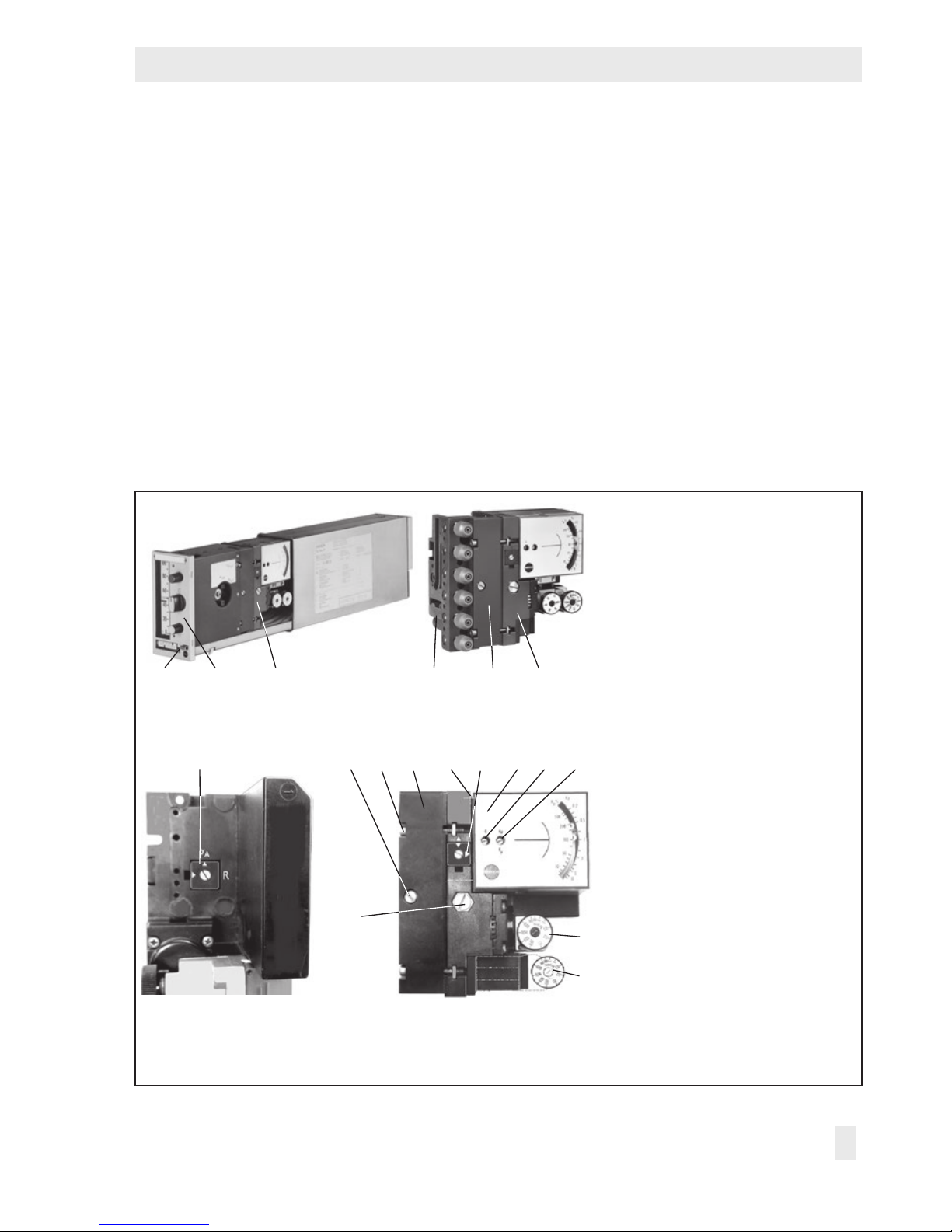
3.1 Settings at the controller
modules
The settings for direction of action and air
delivery must be performed prior to start-up.
Release the lock (4 in Fig.1) on the front
panel of the compact controller and pull the
manual control station completely out of the
housing to access the controller module.
3.1.1 Direction of action
The direction of action for the control loop is
set at the turnboard A. Tshe position of its
arrow symbol according to the arrow symbol
on the controller module determines the
direction of action of the controller (Fig.1).
< > Arrow tips facing opposite directions:
Direction of action increasing/decreas-
ing
As the controlled variable x increases,
the output pressure y falls.
>> Arrow tips facing the same direction:
Direction of action increasing/increas-
ing
As the controlled variable x increases,
the output pressure y increases.
Setting or changing the direction of action:
Unscrew the screw in turnboard A and lift it
off together with the turnboard. If necessary,
lever the board at the side. Do not lose the
rubber seal.
NOTICE
!