Hisun Strike 250 User manual

HiSUN STRIKE 250 LIFT KIT INSTALLATION INSTRUCTIONS
NOTE: Ensure the UTV is safely secured prior to working on it, you will have to remove the
front and rear wheels so a jack stand is recommended for your safety.
Some of the tools needed to install the lift kit will include:
Floor jack
Jack stands
Basic hand tools, wrenches, screwdrivers and some common mechanical experience
Wrenches are in MM not inches

Step 1:
Secure the rear of the HiSUN Strike 250 by using a floor jack and raise the rear of the UTV until the rear wheels are off
of the ground and you are able to place jack stands under the frame. By placing the jack stands on the frame/chassis,
you will allow the rear swing arm free to swing up and down as you install the rear plates. Keep in mind to have the
rear wheels at least a few inches off the ground, as you are going to lower the axle when you install the rear plates.
Step 2:
Remove the rear wheels and place them aside, this allows you easier access to installing the rear lift plates, but it can
be done with the wheel still installed but gives you more room to work.
Step 3: (see pic below)
Loosen the three bolts that hold the lower rear shock into place, and the axle adjuster block upper bolts as well. These
bolts and nuts will be replaced with new ones in the kit.
Loosen the upper shock bolts, to allow the shock to move out of your way freely. The upper shock bolt will be reused.
Step 4:
Loosen the small 8mm bolt holding the rear brake hose and parking brake cable onto the swing arm, you will need to
move the cable/hose out of the way for a little bit.
STEP 3
STEP 4
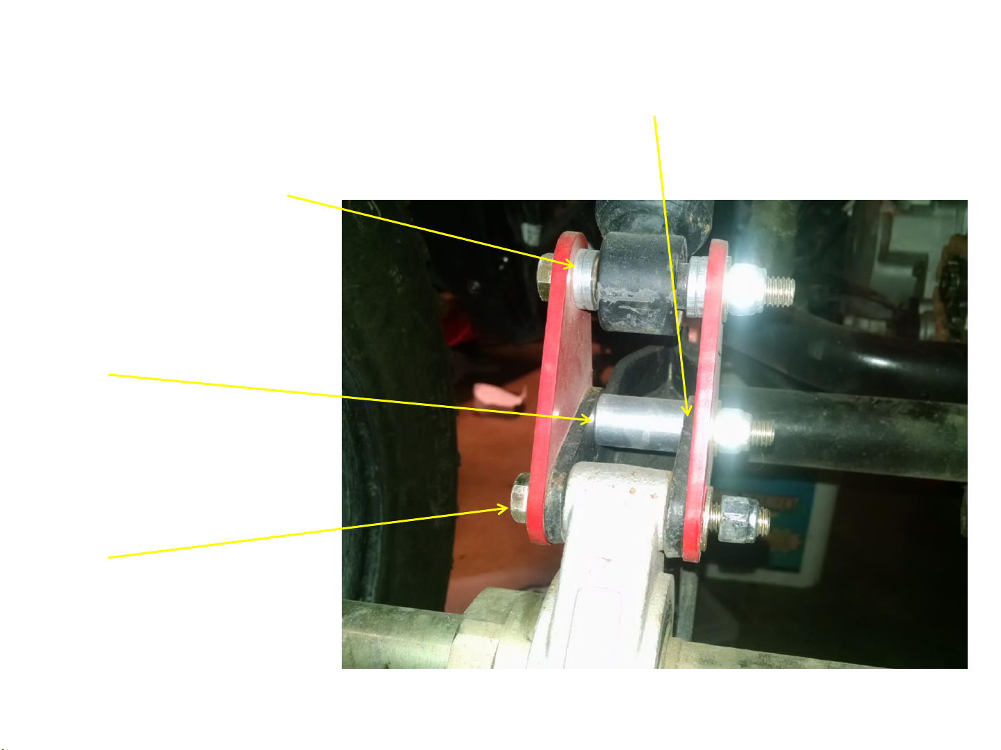
STEP 5:
Next, install the lift plates on the outside of the swing arm base, using the new bolts
supplied.
Step 6:
Using the smaller shims
On the inside of the lift plates
To center the lower shock
Mount as shown in the pic.
There should be two per side.
Step 7:
Using the larger spacer in
Between the swing arm. This
Prevents the bracket from
Bending in on itself.
Step 8:
Install the bolts as shown
With the head facing the
Wheels.

Step 9:
Copying the left side, install the lift kit plates on the right side
Step 10:
This is where you will need to make sure the routing of the brake cable and hose is done
Correctly. They must be routed
Towards the inside of the shock
And lift plate. (shown in the pic)
Step 11:
At this time tighten all of the
nuts and bolts down to 35ft
lbs. of torque. Also make sure
the 8mm bolt to secure the
brake cable on the swing arm is
re-securred at this point.

Step 12:
Once the rear lift kit plates are secured and tight, make sure the upper shock mounting
bolts are tightened. If you removed the rear wheels you can install them back on at this
point. The rear lift kit is done and now installed.
Step 13:
NOTE: you might have to check the chain adjustment at this point since it might have
moved. Please check and adjust the chain to its proper tension per the service manual.
Also check the chain alignment after adjusting by spinning the rear axle after the chain is
adjusted, and you should not hear any binding on the chain to sprocket.
You are now ready to move on to the front lift kit.
Move to the front of the UTV and again, once the front end is secured safely and off the
ground, you can continue.
Step 1:
Remove the front wheels, this will make it easier for you to install the front lift kit.
Remove the upper and lower front shock bolts and remove the shocks. Keep the bolts
nearby as you will use them again.

Step 2 front:
Take the front upper lift plates and slide then inside the upper crossmember. This is where
the upper front shock mounts to.
Step 3 front:
using the supplied spacer, you will install the spacer in-between the upper lift plates, it
might be a tight fit, as some of the OEM brackets are tight and some are loose.
You will be able to slide the plates alone the inside of the U channel where the upper shock
mounted. Using the supplied bolts, secure loosely the top bolt with inner spacer.
(NOTE: now would be a good time to lube the shock eyelets, as they are dry and have no
lube available to them.)
Step 4 front:
Use the OEM shock, bolt it to the lower bolts on the lift brackets, keeping every thing loose
for now. This is done to allow for alignment until every bolt is in place. Lift the front
suspension up with your hands and now secure the lower shock eye to mount to the OEM
position with the stock OEM bolt you removed. Perform this for both sides.
Step 5 front:
Once the lift kit brackets are installed and all the shock bolts are secured back, you can go
through and tighten the bolts to approx. 35ft lbs.
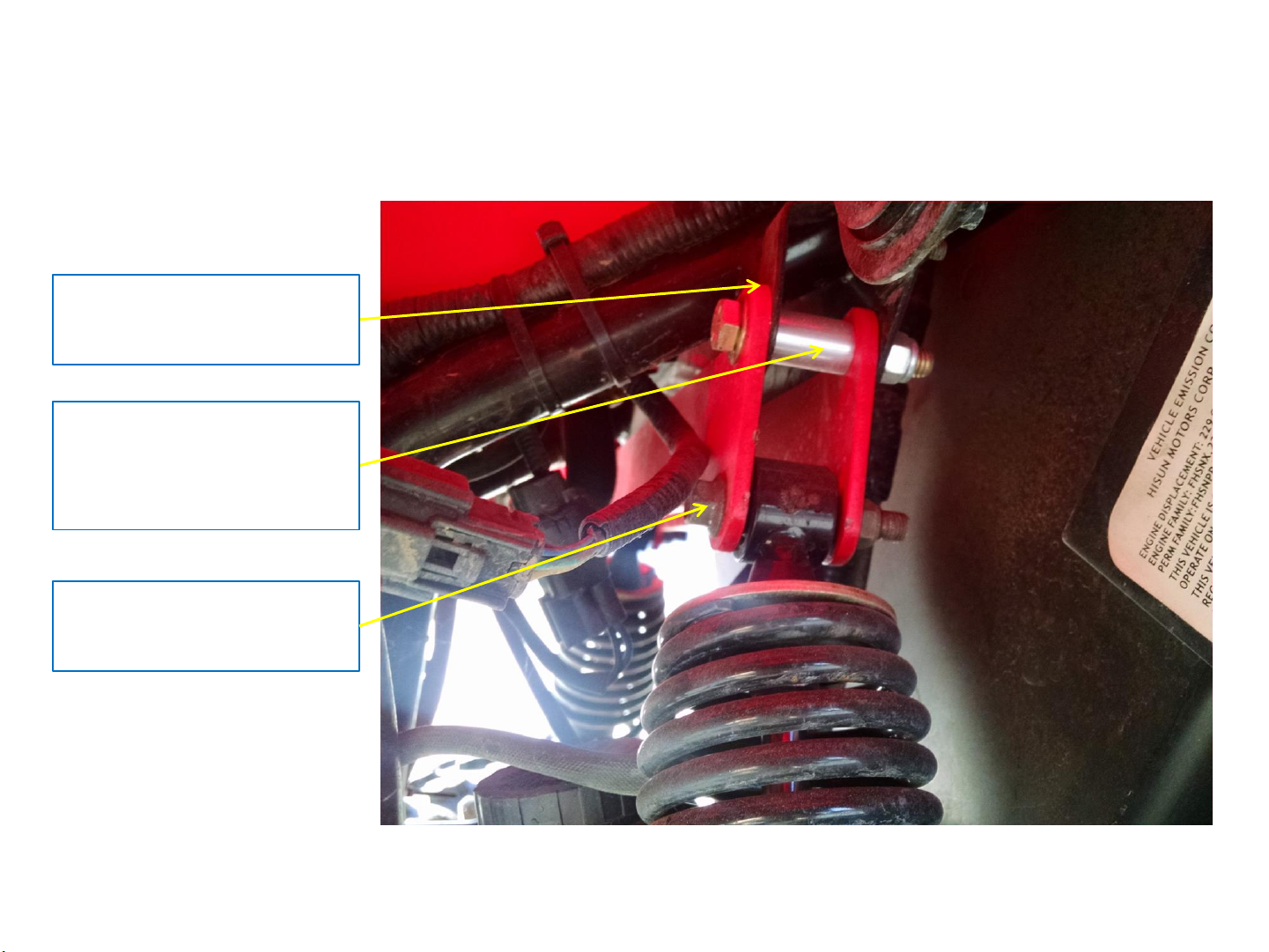
In this photo, you can see how the plates are placed, one is on the inside of the OEM
shock mount, and the forward plate is on the outside of the U channel. Put the upper
spacer as shown. The lower shock mount does not take any spacers. It uses OEM bolts to
secure it.
Forward plate on
outside of U channel
Spacer in-between U
channel and rear lift
plate
Use OEM shock bolt
to install upper shock

These photos help to show the proper
placement of the lift kit plates.
Once the are installed and tightened, you
can re-install the front wheels and tighten
to OEM specs.
NOTE: be sure to check for clearance with
all hoses, lines, and movement of the
shocks prior to driving.

HiSUN STRIKE 250 LIFT KIT 2”
At this point you should have the complete kit installed and tightened. Remove off the jack
stands and using your body weight, I would bounce the UTV up and down a few times to
check operation prior to taking out for a first drive. Make sure you have tightened all nuts
and bolts. If you have any questions at this point, please contact me with your problem
right away.
Now, go out and have some fun with more ground clearance available. I have also installed
wheel spacer of 2” on our units. The wheel pattern is the same as the Yamaha Banshee, so
finding a set online is very easy if you want that same look as our units.
Have fun and enjoy your taller Hisun for some more off road adventures.
Matt Tate
www.250utv.com
Lakewood Ca 90713
562-682-7859
STOCK 2” LIFT
Other manuals for Strike 250
1
Popular Lifting System manuals by other brands


SYSTEMS
SYSTEMS McGuire VSH Series Owner & user manual

Braun Corporation
Braun Corporation Under-Vehicle Lift 2 Series Service manual

Hubbell
Hubbell EH-09 Installation and operation instructions

Space
Space SDE2250LIKA Translation of the original instructions

Manitou
Manitou 160 ATJ PLUS Euro 3 Operator's manual

AMGO Hydraulics
AMGO Hydraulics OH-12 Installation and service manual

Sunex Tools
Sunex Tools 4412 owner's manual

Bayne
Bayne Thinline DTL 1116 Operation and parts manual

QUALITY LIFTS
QUALITY LIFTS Q4P07 Installation, operation & maintenance manual

Genie
Genie ZX-135/70 with Jib-Extend Service and repair manual

Drive
Drive 13023 instructions

Vestil
Vestil CYL-D-1-PN instruction manual