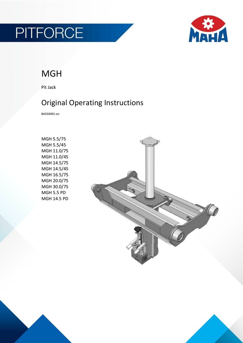
MAHA Pitforce AB User manual

Fehler! Verwenden Sie die Registerkarte 'Start', um Name dem Text zuzuweisen, der hier angezeigt werden soll.Fehler! Verwenden Sie
die Registerkarte 'Start', um Name dem Text zuzuweisen, der hier angezeigt werden soll.Fehler! Verwenden Sie die Registerkarte
'Start', um Name dem Text zuzuweisen, der hier angezeigt werden soll.
AB | ABA | ABT | AT-NB | ATV | SAT
Lifting Accessories for Pit Jacks
Original Operating Instructions
BA551101-en
Pos: 1 / -----F or m at---- -/MAN UEL LE R UM B RUC H Seite numb r uc h @ 0\m od_ 11 3 4403 5 77 687_ 0.d ocx @ 1 277 @ @ 1

2
BA551101-en
Pos: 2 / -----F or m at---- -/Inh a ltsv er ze ic hn is - 2 Eb e ne n @ 43\m od_1448887680115_75.docx@ 2352724@ @ 1
Contents
1Safety ......................................................................................................................3
1.1 Introduction......................................................................................................................................... 3
1.2 Symbols .............................................................................................................................................. 3
1.3 Intended Use....................................................................................................................................... 3
1.4 Inappropriate Use................................................................................................................................ 3
1.5 Safety Instructions for Operation ......................................................................................................... 4
1.6 Combination with Accessories ............................................................................................................ 5
1.7 What to Do in the Event of an Accident............................................................................................... 5
2Transport and Storage .............................................................................................5
3Installation and Initial Operation ................................................................................5
4General Information..................................................................................................6
4.1 Description .......................................................................................................................................... 6
4.2 Sample Nameplate.............................................................................................................................. 6
4.3 Coefficient for Static Testing................................................................................................................ 6
4.4 Requirements on the Foundation Bearing Capacity of the Workshop Pit............................................. 7
4.5 Requirements on Suitable Lifting Devices............................................................................................ 7
4.6 Requirements on the Operator ............................................................................................................ 7
4.7 General Operating Instructions for Lifting Accessories ......................................................................... 8
5Support Systems AB / ABT / ABA / AT-NB ..............................................................9
5.1 Specifications ...................................................................................................................................... 9
5.2 Operating the Axle Crossbar AT-NB (Asymmetrical Load Center)...................................................... 14
6Axle Crossbar SAT 14.5 .........................................................................................15
6.1 Specifications .................................................................................................................................... 15
6.2 Operation .......................................................................................................................................... 16
7Axle Crossbar ATV 3.5 ...........................................................................................18
7.1 Specifications .................................................................................................................................... 18
7.2 Operation .......................................................................................................................................... 19
8Maintenance ..........................................................................................................20
8.1 Annual Inspection.............................................................................................................................. 20
8.2 Care Instructions ............................................................................................................................... 20
8.3 Greasing Points................................................................................................................................. 20
8.4 Spare Parts ....................................................................................................................................... 20
9Service Lifetime......................................................................................................21
10 Dismantling ............................................................................................................21
11 Disposal.................................................................................................................21
12 Contents of the Declaration of Conformity ..............................................................21
13 Company Information.............................................................................................22
Pos: 3 / Te chnisc he D okum entat ion/A lle Ger äte/ Über schrif ten/Üb ersc hrift en 1/S/ Über schri ft 1: Sicherhei t @ 6\mod_1174482399906_75.docx@ 76962@ 1 @ 1
3
BA551101-en
1
Safety
Pos: 4 / Te chnisc he D okum entat ion/A lle Ger ä te/Üb erschr ifte n/Übers chr iften 1 .1/E/ Übersc hrif t 1. 1: E inführu ng @ 6\mod_1174482219062_75.docx @ 76793@ 2 @ 1
1.1
Introduction
Pos: 5 / Te chn isc he Dokum en tat ion/ A ll e G er ä te/I nha lte/ S ic her he it/In ha lt : Ei nf ühr u ng Si cher hei t_ 12p t @2 5\mod_1324455248318_75.docx@ 1138886@ @1
Thoroughly read this manual before operating the equipment and comply with the
instructions. Always display the manual in a conspicuous location.
Personal injury and property damage incurred due to non-compliance with these
safety instructions are not covered by the product liability regulations.
Pos: 6 / Te chnisc he D okum entat ion/A lle Ger ä te/Üb erschr ifte n/Übers chr iften 1 .1/S/ Über schri ft 1.1: Symbo le @ 6\mod_1174482270875_75.docx@ 76865@ 2 @ 1
1.2
Symbols
Pos: 7 / Te chnisc he D okum entat ion/A lle Ger ä te/In halte/S iche rhe it/ In ha lt : S ym bo le Sicher hei t_ 12p t @ 25\m od_1324456650897_75.docx@ 1139046@ @ 1
Important safety instructions. Failure to comply with instructions could result in
personal injury or property damage.
Important information.
Pos: 8 / Te chnisc he D okum entat ion/A lle Ger äte/ Über schrif ten/Üb ersc hrift en 1 .1/B/Üb ersc hrift 1 .1: B estim mungs gemä ßer G ebr auch @ 6\mod _1176 7340 22203_ 75.d ocx @ 8874 6 @ 2 @ 1
1.3
Intended Use
Pos: 9 / Te chn is c he Dokum en ta ti on/ He be te c hn ik/ PIT FO R CE /55 1 10 1 A B / ABA / A BT / AT-NB / ATV / SA T/ BA/ I nh a lt: 551 1 B es t imm u ngs gem ä ßer Geb r auc h L AM @ 29\m od_1 33974 69063 04_75.d ocx @ 1 60822 3 @ @ 1
The support systems, support bridges and axle crossbars are exclusively intend-
ed, according to their rated load capacity, for the use as lifting accessories with
suitable lifting devices, in accordance with EN 1494. They are used for the safe
supporting, lifting, lowering and placing on the ground of vehicles in working pits
of commercial vehicle workshops, in closed rooms at environmental temperatures
ranging from +5 to +40 °C.
Pos: 1 0 / Techn ische Dokument atio n/Alle Geräte/Über sc hriften/ Über schri ften 1.1/B/ Überschr ift 1.1: Bes timm ungsw idr iger Geb rauc h @ 18\m od_1255530265027_75.docx@ 471571 @ 2@ 1
1.4
Inappropriate Use
Pos: 1 1 / Tec hn is ch e Dokumentation/Hebetechnik/PITFORCE/551101 AB/ ABA / ABT/ AT-NB / A TV / SA T/ BA /I n ha lt: 5511 Bes timm un gs w id rige r Gebr au c h L AM @ 27\mod_1328786120213_75.docx@ 1543690@ @1
Use beyond the scope of the intended purpose shall be considered as improper
use, e.g. use for other lifting works.
Use on sloping, uneven surfaces which may cause the device to tip over, is
prohibited.
Use in areas subject to explosion hazards and outdoors is prohibited. Use in
damp or areas subject to fire hazards is only permitted with the express, written
approval of the manufacturer.
The device may not be modified without the express, written approval of the
manufacturer. In the case of non-compliance, the declaration of conformity shall
lose its validity.
Pos: 1 2 /----- Form a t-----/M A N UE L LER UM BR UCH Sei ten u mb r uch @ 0\m od_1134403577687_0.docx @ 1277 @ @1

4
BA551101-en
Pos: 1 3 / Techn ische Dokument atio n/Alle Geräte/Über sc hriften/ Über schri ften 1.1/S/Über sc hrift 1.1:S ic herhe itsvor schr iften f ür d en B etrieb @ 6\mod_1174482268953_75.docx @ 76826 @ 2 @ 1
1.5
Safety Instructions for Operation
Pos: 14 / Tec hnisch e Do kume ntatio n/Hebet echni k/PIT FORCE/ 5511 01 AB / ABA / ABT / AT-N B / A TV / SA T/ BA/ In ha lt: 55 11 S ic her h ei tsv ors c hr if ten für d e n Betr ieb LAM @ 29\m od_1339747293146_75.docx@ 1608268@ @ 1
•Transportation only by trained personnel and with a suitable tool.
•Observe notes with regard to possible dangers during mounting or ensuring
correct handling.
•shall only be carried out by authorised personnel.
•Mounting, commissioning, adjusting, operating, maintenance, repairs and de-
mounting shall only be carried out by trained and authorised personnel.
•In the event that a person is not strong enough to operate the device manually,
a suitable tool or another person should be called upon.
•The operator is responsible for ensuring that the user is instructed and familiar
with the operating instructions.
•The maximum permissible positioning speed of the load-carrying equipment is
0.01 m/s. Only operation by hand is allowed.
•The maximum permissible load depositing speed is 0.1 m/s.
•During the positioning of the actuators, no limbs shall be in the hazard area.
•Load-carrying equipment, actuator and accessory kit shall be tested before use
for operational safety. The load-carrying equipment shall only be operated in a
safe and slip-resistant state.
•Actuators should be protected from falling with suitable protection parts. Oper-
ation is not permitted until missing or defective protection parts are implement-
ed according to the replacement parts list.
•The load bearing capacity specified on the name plate must not be exceeded.
•The load centre shall only be centrically carried.
•During operation when the load is in an unsecured condition, no-one must be in
the hazard area.
•Before depositing, the operator must ensure that no objects are located in load
movement area which could prevent a safe support.
•After the end of operation and before each transportation, all assembly parts
must be removed from the load-carrying system and stored in a suitable place.
•The markings and notes on the device shall be checked regularly for readability
for the entire life span and, if necessary, replaced according to the replacement
parts list.
•Maintenance and repairs shall be carried out according to the manufacturer's
stipulations by an expert.
Pos: 1 5 /----- Form a t-----/M A N UE L LER UM BR UCH Sei ten u mb r uch @ 0\m od_1134403577687_0.docx @ 1277 @ @1

5
BA551101-en
Pos: 1 6 / Techn ische Dokument atio n/Alle Geräte/Über sc hriften/ Über schri ften 1.1/K/Üb erschr ift 1.1: Komb ina tion mi t Zub eh ör @ 9\mod_1212051386858_75.docx@ 214986@ 2 @ 1
1.6
Combination with Accessories
Pos: 1 7 / Techn ische Dokument atio n/Alle Geräte/Inh alte/ Sich erhe it/Inhal t: K ombin ation m it Z ub ehör_1 2pt @ 25\mod_1324455653416_75.docx @ 1138909 @ @ 1
The equipment shall be operated only with accessories offered, approved or
permitted by the manufacturer.
Pos: 18 /Techn ische Dokume ntation/Al le Geräte/Über schrift en/Überschr iften 1.1/V /Überschr ift 1.1: Verhal tenb ei Unfällen @ 1 9\mod_12 67177 2453 37_7 5.docx @ 794 600 @ 2 @ 1
1.7
What to Do in the Event of an Accident
Pos: 19 /Techn ische Dokume ntation/Al le Geräte/Inh alte/Sicher heit/Inhal t: Verhalten bei U nfällen_12p t @3 4\mod_1381128863435_75.docx@ 1837175@ @ 1
•The injured person is to be removed from the danger area. Find out where
dressing and bandages are kept. Seek first-aid.
•Provide first-aid (stop bleeding, immobilise injured limbs), report the accident
and seal off the accident site.
•Immediately report any accident to your supervisor. Make sure a record is kept
of every occasion first-aid is provided, e.g. in an accident book.
•Remain calm and answer any questions that may arise.
Pos: 2 0 / Techn ische Dokument atio n/Alle Geräte/Über sc hriften/ Über schri ften 1/T/Über schri ft 1: Tr ansp ort und Lageru ng @20\mod_1268732488860_75.docx@ 826153@ 1 @ 1
2
Transport and Storage
Pos: 21 /Techn ische Dokume ntation/ Alle Geräte/ Inhalte/Inh alt: Transp ort und Lageru ng_12pt @ 2 6\mod_1324468980166_75.docx@ 1141285@ @ 1
Check package to ensure it is complete, in accordance with the order
confirmation. Report any transport damage to the carrier immediately.
During loading, unloading and transport always use suitable lifting equipment,
material handling equipment (e.g. cranes, forklifts, etc.) and the right load handling
attachments and slings. Always ensure that the parts to be transported are
suspended or loaded properly so that they cannot fall, taking into account size,
weight and the centre of gravity.
Store the packages in a covered area, protected from direct sunlight, at a low
humidity and with temperatures between 0...+40 °C (32…104 °F). Do not stack
packages.
When unpacking, take care to avoid any possibility of injury or damage. Keep at a
safe distance when opening the package strapping, do not allow any parts to fall
out.
Pos: 2 2 /----- Form a t-----/M AN UE L LER UMBR UC H Z e ile ns c ha lt un g @ 7\mod_ 1195 1389 65731_ 0.docx @ 132 177 @ @ 1
Pos: 2 3 / Techn ische Dokument atio n/Alle Geräte/Über sc hriften/ Über schri ften 1/M/Übers chr ift 1 : M ontag e und E rst inbe triebn ahme @18\mod_1255417443299_75.docx @ 463797@ 1 @ 1
3
Installation and Initial Operation
Pos: 24 /Techn ische Dokument ation/Alle Ger äte/Inhal te/Inhalt: Mon tage und Erstinb etriebnahm e_12pt @ 26\mod_1324468562877_75.docx @ 1141153@ @1
Installation and initial operation of the equipment may be done only by authorized
and trained service technicians provided by the manufacturer, licensed dealers or
service partners.
Pos: 2 5 /----- Form a t-----/M A N UE L LER UM BR UCH Sei ten u mb r uch @ 0\m od_1134403577687_0.docx @ 1277 @ @1

6
BA551101-en
Pos: 26 /Techn ische Dokument ation/Alle Ger äte/ Übersc hrift en/ Überschr ifte n 1/A/ Übers chr ift 1: Allgemei nes @ 15\mod_ 12432 47897 354_ 75.do cx @ 376 952 @ 1 @ 1
4
General Information
Pos: 2 7 / Techn ische Dokument atio n/Alle Geräte/Über sc hriften/ Über schri ften 1.1/B/ Überschr ift 1.1: Bes chre ibung @ 16\m od_1 246527377649_75.docx @ 400654@ 2 @ 1
4.1
Description
Pos: 28 / Tec hnisch e Do kume ntatio n/Hebet echni k/PIT FORCE/ 5511 01 AB / ABA / ABT / AT-N B / ATV / SA T/BA/ Inha lt: 5511 Be schr eibun g Allg LAM @ 29\mod_1339747743683_75.docx@ 1608313@ @ 1
Support systems, support bridges and axle crossbars are lifting accessories for
supporting, raising, lowering and, depending on type, for carrying vehicles in order
to, among other, work on these safely. The suitability must be determined by the
type-specific technical data, functional descriptions, operating and safety instruc-
tions.
After the vehicle has been properly supported, the previously used lifting device
can be used for other tasks such as removing of assemblies or raising and lower-
ing of other vehicle axles.
Pos: 2 9 / Techn ische Dokument atio n/Alle Geräte/Über sc hriften/ Üb erschr ifte n 1. 1/T/ Übers chrift 1.1: Typ ensch ild-M ust er @ 11\m od_12 27622 2060 96_7 5.docx @ 27 5574 @ 2 @ 1
4.2
Sample Nameplate
Pos: 3 0 / Techn ische Dokument atio n/Hebet ech nik/PI TFORCE /5 5110 1 AB / ABA / ABT / AT-NB / A TV / SA T/BA / In ha lt: 55 11 Ty p e ns ch ild LAM (MAH A) @ 28\mod_1335945278523_75.docx @ 1591401@ @ 1
Lifting Accessories for Pit Jacks
Ser. Number / Year of Prod.: ***
Project: ***
Model and Version: ***
Load Capacity: ***
Net Weight: ***
Pos: 3 1 / Tec hn is ch e Dokument ation/Alle Ger äte/Übers chriften/ Überschri ften 1.1/K/Üb erschrif t 1.1: Koeffiz ient für die statisc he Prüfung @ 2 9\mod_1340017216213_75.docx@ 1609233@ 2 @ 1
4.3
Coefficient for Static Testing
Pos: 3 2 / Techn ische Dokument atio n/Hebet ech nik/PI TFORCE /5 5110 1 AB / ABA/ AB T/ AT-NB / ATV / SA T/BA /I n ha lt: 55 11 K oe ff iz ie nt statis ch e Pr üf un g @ 29\mod_1340017479770_75.docx@ 1609277 @ @ 1
Coefficient for static testing with all lifting accessories........................................1,5
Pos: 3 3 /----- Form a t-----/M A N UE L LER UM BR UCH Sei ten u mb r uch @ 0\m od_1134403577687_0.docx @ 1277@ @ 1

7
BA551101-en
Pos: 3 4 / Techn ische Dokument atio n/Alle Geräte/Über sc hriften/ Über schri ften 1.1/A/Über sc hrift 1.1:A nf order ungen an die F undam en tfes t igk e it d er Arbei tsgr ub e @ 29\mod_1339747974635_75.docx @ 1608358@ 2 @ 1
4.4
Requirements on the Foundation Bearing Capacity of the Workshop
Pit
Pos: 35 / Tec hnisch e Do kume ntatio n/Hebet echni k/PIT FORCE/ 5511 01 AB / ABA / ABT / AT-N B / ATV / SAT/BA /I nha lt: 5511 Grubenb e las tu ng LAM @ 2 8\mod_1337857396849_75.docx @ 1601355@ @ 1
The support systems shall be used only in conjunction with workshop pits which
have a suitable foundation. For maximum loads applied to the pit edge see table
below.
Load capacity
overall
Load capacity
per edge
Ruled surface
30 x 40 mm
Wheel deflec-
tor
30 x 10 mm
[t] [t] [N/mm2] [N/mm2]
SAT 14.5 14.5 7.25 33 134
AB/ABT/AT-NB 14.5 7.25 33 134
AB/ABT 20 10 46 185
ABA 4 2 9 37
Pos: 3 6 / Techn ische Dokument atio n/Alle Geräte/Über sc hriften/ Über schri ften 1.1/A/Über sc hrift 1.1:A nf order ungen an gee igne tes H u bger ä t @ 29\m od_1339749659024_75.docx@ 1608452@ 2 @ 1
4.5
Requirements on Suitable Lifting Devices
Pos: 37 / Tec hnisch e Do kume ntatio n/Hebet echni k/PIT FORCE/ 5511 01 AB / ABA / ABT / AT-N B / A TV / SA T/ BA/ In ha lt: 55 11 A nf or der un ge n a n geei gne tes Hub ge rä t @ 2 9\mod_1339749814133_75.docx@ 1608496@ @ 1
The lifting accessories shall be used only in conjunction with lifting devices that
meet the following requirements:
•Inside diameter of cylinder 45 or 55 mm (depending on design of lifting acces-
sory)
•Outside diameter of cylinder > 60 mm (depending on design of lifting accesso-
ry)
•Lifting device in accordance with harmonised standard EN 1494 and EC di-
rective 2006/42/EC
Pos: 3 8 / Techn ische Dokument atio n/Papi erkorb /Über sc hriften/ Über schrif t 1. 1: Anf ord erun gen a n de n Bediener @ 1 8\mod_1255531954990_75.docx@ 471737@ 2 @ 1
4.6
Requirements on the Operator
Pos: 39 /Techn ische Dokume ntation/Al le Geräte/Inh alte/Warnu ng!/Inhalt: W arnung - Anf orderungen an d en Bediener_1 2pt @ 26\mod_1324464226462_75.docx @ 1140361@ @ 1
All persons employed in the operation, maintenance, installation, removal and dis-
posal of the device must
•be at least 18 years old,
•be trained and instructed in writing,
•have read and understood this manual
•be on record as having been instructed in safety guidelines.
Pos: 4 0 /----- Form a t-----/M A N UE L LER UM BR UCH Sei ten u mb r uch @ 0\m od_1134403577687_0.docx @ 1277 @ @1

8
BA551101-en
Pos: 4 1 / Techn ische Dokument atio n/Alle Geräte/Über sc hriften/ Über schri ften 1.1/A/Über sc hrift 1.1:A llgem ei ne Bed ienun gshin weis e f ür Lasta ufn ahm em it te l @ 29\mod_1339752194845_75.docx@ 1608540@ 2 @ 1
4.7
General Operating Instructions for Lifting Accessories
Pos: 42 / Tec hnisch e Do kument ation/ Hebet echni k/PIT FORCE/5 511 01 AB / ABA / ABT / AT-N B / A TV / SA T/ BA/ I n ha lt: 5511 Bed ien un g Allg LA M @ 2 9\mod_1339752500818_75.docx @ 1608634@ @ 1
•Support tubes must not be extended. Risk of tilting!
•Danger of crushing at the edge of the pit and support bridge!
•The support system shall only be removed if the vehicle is in a secure stable position.
•
Beware of changes in the centre of gravity of the load, e.g. in case of different amounts
of fuel in asymmetric fuel systems. If necessary, use suitable lifting accessories.
•Take note of the operating instructions of all equipment and tools used.
•Check lifting accessories carefully for operational safety.
•Pre-position the lift and lifting accessory at the lift points.
•Always take up the load securely, without risk of slipping and central to the centre of
gravity.
•Position actuators, supports and bases at the support points and depending on type,
fix support pipes with pins and secure with cotter pins or wooden blocks with a mini-
mum spacing of 500 mm.
•Slowly raise or lower the load, watching it continuously.
•Set down the load without risk of slipping and central to the centre of gravity.
Pos: 43 / Tec hnisch e Do kume ntatio n/Hebet echni k/PIT FORCE/ 5511 01 AB / ABA / ABT / AT-N B / ATV / SA T/ BA/ In ha lt: 5511 V e rlä n ge r un g b e i H ub ger ä ten und L A M ( Te xt) @ 2 7\mod_1328787763776_75.docx@ 1543954@ @1
Permissible Extension for Pit Jack and Support Systems
Pos: 4 4 / Techn ische Dokument atio n/Hebet ech nik/PI TFORCE /5 5110 1 AB / ABA / ABT/ AT-N B / A TV / SA T/B A/ In ha lt : 5 5 11 V e rlä ng er un g be i H ub ger ä ten und LAM ( B ild er ) @ 24\mod _ 13 106 29 438 4 81_ 0.d ocx @ 1 02 387 7 @ @1
Pos: 4 5 /----- Form a t-----/M A N UE L LER UM BR UCH Sei ten u mb r uch @ 0\m od_1134403577687_0.docx @ 1277 @ @1

9
BA551101-en
Pos: 46 /Techn ische Dokument ation/Alle Ger äte/Übersc hriften/ Überschrifte n 1/A/Übersc hrift 1: Abstützs ysteme AB / ABT / ABA / AT-NB @ 28\mod_1337080161244_75.docx@ 1597771@ 1 @ 1
5
Support Systems AB / ABT / ABA / AT-NB
Pos: 4 7 / Tec hn isch e Dokume nt atio n/ Al le Ger äte/ Übersc hrift en/ Überschr ifte n 1. 1/T/Üb erschr ift 1. 1: Te chnis che D aten @ 7\mod_1184075526343_75.docx @ 99711@ 2 @ 1
5.1
Specifications
Pos: 4 8 / Tec hnisch e Dokumentat ion/ Alle Geräte/Über sc hrift en/ Übers chrif ten 1.1.1/A/Über sc hrif t 1.1.1 : A bs tützsys tem ABA @ 29\mod_1339762578201_75.docx@ 1608904@ 3 @ 1
5.1.1
Support System ABA
Pos: 49 / Tec hnisch e Do kume ntatio n/Hebet echni k/PIT FORCE/ 5511 01 AB / ABA / ABT / AT-N B / ATV / SA T/BA /I n ha lt: 5 5 11 Te c hnis che Dat en ( Bi ld) ABA @ 2 8\mod _ 13 378 62 351 5 40_ 0.d ocx @ 1 601 44 4 @ @1
Pos: 5 0 /----- Form a t-----/M A N UE L LER UM BR UCH Sei ten u mb r uch @ 0\m od_1134403577687_0.docx @ 1277 @ @1

10
BA551101-en
Pos: 5 1 / Tec hnisch e Dokumentat ion/ Alle Geräte/Über sc hrift en/ Übers chrif ten 1.1.1/A/Über sc hrif t 1.1.1 : A bs tützsys tem AB @ 29\mod_ 13 39 7 626 35062_75.docx@ 1608948@ 3 @ 1
5.1.2
Support System AB
Pos: 52 / Tec hnisch e Do kume ntatio n/Hebet echni k/PIT FORCE/ 5511 01 AB / ABA / ABT / AT-N B / A TV / SA T/ BA/ In ha lt: 55 11 Te c hn is che Dat en ( Tab e ll e) A B @ 27\m od_1328787375645_75.docx @ 1543822@ @1
Support System
AB
Support
Position
Dimension A or B (min – max) dep. on Side Part
used
Version
"A/C" Version "B" Version
"D/F" Version "E"
Standard VZ 975567
Desig-
nation
Ordering
Code
AP =
400-1104
BG =
890-1320
BG =
820-1220
BG =
840-1280
BG =
960-1330
Beam 1 Standard 400-804 890-1030 820-960 840-980 960-1090
Beam 2 Standard 460-864 950-1090 880-1020 900-1040 1020-1150
Beam 3 VZ 975566 520-924 1010-1150 940-1080 960-1100 1080-1210
Beam 4 VZ 975566 580-984 1070-1210 1000-1140 1020-1160 1140-1270
Beam 5 VZ 975566 640-1044 1130-1270 1060-1200 1080-1220 1200-1330
Beam 6 VZ 975566 700-1104 1190-1330 1120-1260 1140-1280 -
Dimension
(max. overall)
Dimension (Reference
surface: Pit profile) Profile fea-
tures
Ordering
Code
Desig-
nation Version "H" "G" "C" "D" "E" "F"
Side Part "A/B/C" 185 521 107 200 85 99 from U 220 Standard
Side Part "A/B/C" 165 501 87 180 65 79 from U 200 VZ 975568
Side Part "A/B/C" 220 556 142 235 120 134 from U 260 VZ 975568
Side Part "D/F" 90 426 5 98 -17 -3 Special VZ 975567
Side Part "E" 60 396 -35 58 -57 -43 Special VZ 975567
Total net weight: approx. 120 kg
Pos: 5 3 /----- Form a t-----/M A N UE L LER UM BR UCH Sei ten u mb r uch @ 0\m od_1134403577687_0.docx @ 1277 @ @1

11
BA551101-en
Pos: 54 / Tec hnisch e Do kume ntatio n/Hebet echni k/PIT FORCE/ 5511 01 AB / ABA / ABT / AT-N B / ATV / SA T/BA /I n ha lt: 5 5 11 Te c hnis che Dat en ( Bi ld) AB @ 24\mod_1309359381115_0.docx@ 1020033@ @1
Pos: 5 5 / Techn ische Dokument atio n/Hebet ech nik/PI TFORCE /5 5110 1 A B/ ABA / ABT/ AT-N B / A TV / SA T/ BA/ In ha lt: 55 11 Te c hn is che Dat en ( Le ge nd e) A B/ AB T @ 29\mod_1340201684617_75.docx @ 1610103@ @ 1
X
Label: Load capacity
Y
Label: Short operating instructions
Pos: 5 6 / Tec hn is ch e Dokumentation/Hebetechnik/PITFORCE/551101 AB /A BA/ ABT/ AT-NB / A TV / SA T/BA /I n ha lt: 5511 V a ria nt e n ( Bi ld er ) A B @ 24\m od_1310638472392_0.docx @ 1024042 @ @ 1
Pos: 5 7 / Techn ische Dokument atio n/Hebet ech nik/PI TFORCE /5 5110 1 AB / ABA/ AB T/ AT-NB / ATV / SA T/BA /I n ha lt: 5511 V a ria nte n A-F ( Tex t) @ 27\m od_1328787587112_75.docx @ 1543866@ @ 1
Version A Version B Version C Version D Version E Version F
Pos: 5 8 /----- Form a t-----/M A N UE L LER UM BR UCH Sei ten u mb r uch @ 0\m od_1134403577687_0.docx @ 1277 @ @ 1

12
BA551101-en
Pos: 5 9 / Tec hnisch e Dokumentat ion/ Alle Geräte/Über sc hrift en/ Übers chrif ten 1.1.1/A/Über sc hrif t 1.1.1 : A bs tützsys tem ABT @ 29\mod_1339762684061_75.docx@ 1608992@ 3 @ 1
5.1.3
Support System ABT
Pos: 6 0 / Tec hn is ch e Dokumentation/Hebetechnik/PITFORCE/551101 AB /A BA/ ABT/ AT-NB / ATV / SA T/B A/I n ha lt: 5511 Tech nis c he D at e n ( Ta be ll e) A B T @ 2 4\mod_1310455258479_75.docx@ 1023113@ @1
Support system ABT Support
position
Pit dimension A or B (min-max) dep. on side part used
Version
"A/C"
Version
"B"
Version
"D/F"
Version
"E"
Standard VZ 975567
Desig-
nation Order code
AP BG =
890...1320
BG =
820...1220
BG =
840...1280
BG =
960...1330
Beam 1 Standard 80…1010 890...1030 820...960 840...980 960...1090
Beam 2 Standard 80...1010 950...1090 880...1020 900...1040 1020...1150
Beam 3 VZ 975566 80...1010 1010...1150 940...1080 960...1100 1080...1210
Beam 4 VZ 975566 80...1010 1070...1210 1000...1140 1020...1160 1140...1270
Beam 5 VZ 975566 80...1010 1130...1270 1060...1200 1080...1220 1200...1330
Beam 6 VZ 975566 80...1010 1190...1330 1120...1260 1140...1280 ---
Dim. (max.
overall)
Dim. (Reference surface pit
profile)
Profile fea-
ture Order code
Design. Version "H" "G" "C" "D" "E" "F"
Side part "A/B/C" 185 650 107 200 87.5 99 from U 220 Standard
Side part "A/B/C" 165 630 87 180 67.5 79 from U 200 VZ 975568
Side part "A/B/C" 220 870 142 235 122.5
134 from U 260 VZ 975568
Side part "D/F" 90 555 5 98 -14.5 -3 Special VZ 975567
Side part "E" 60 525 -35 58 -54.5 -43 Special VZ 975567
Overall net weight: approx. 180 kg
Pos: 61 / Tec hnisch e Do kume ntatio n/Hebet echni k/PIT FORCE/ 5511 01 AB / ABA / ABT / AT-N B / ATV / SA T/BA /I n ha lt: 5 5 11 Te c hnis che Dat en ( Bi ld) AB T @ 24\mod_1309359896940_0.docx @ 1020063@ @ 1

13
BA551101-en
Pos: 62 / Tec hnisch e Do kume ntatio n/Hebet echni k/PIT FORCE/ 5511 01 AB / ABA / ABT / AT-N B / A TV / SA T/ BA/ In ha lt: 55 11 Te c hn is che Dat en ( Le ge nd e) A B/ AB T @ 29\mod_1340201684617_75.docx @ 1610103@ @ 1
X
Label: Load capacity
Y
Label: Short operating instructions
Pos: 63 / Tec hnisch e Do kume ntatio n/Hebet echni k/PIT FORCE/ 5511 01 AB / ABA / ABT / AT-N B / A TV / SA T/ BA/ In ha lt: 55 11 V ar ia nte n ( Bi ld er ) A BT @ 2 8\mod_1337861605624_0.docx @ 1601400@ @ 1
Pos: 6 4 / Tec hn is ch e Dokumentation/Hebetechnik/PITFORCE/551101 AB /A BA/ ABT/ AT-NB / A TV / SA T/BA /I n ha lt: 5511 V a ria nt e n A -F ( Tex t) @ 27\m od_1328787587112_75.docx@ 1543866@ @ 1
Version A Version B Version C Version D Version E Version F
Pos: 6 5 /----- Form a t-----/M A N UE L LER UM BR UCH Sei ten u mb r uch @ 0\m od_1134403577687_0.docx @ 1277 @ @1

14
BA551101-en
Pos: 6 6 / Techn ische Dokument atio n/Alle Geräte/Über sc hriften/ Über schri ften 1.1/B/ Überschr ift 1.1: Bed ienun g der Achstr averse AT-NB @ 29\mod_1339756090988_75.d ocx @ 16 08679 @ 2 @ 1
5.2
Operating the Axle Crossbar AT-NB (Asymmetrical Load Center)
Pos: 67 / Tec hnisch e Do kume ntatio n/Hebet echni k/PIT FORCE/ 5511 01 AB / ABA / ABT / AT-N B / ATV / SAT/BA/I nha lt: 5 511 Bed ien ung N ieder flur traver se AT-N B ( Tex t ) @ 29\mod _133 9756 390082_ 75.d ocx @ 160 8723 @ @ 1
•The general operating instructions for load accessories must be observed.
•Pre-position actuators central to the crossbar at the lifting points.
•Pre-position the lifting accessory central to the load’s centre of gravity.
•If necessary, identify the centre of gravity again in the case of asymmetry or
change. To do this, briefly raise the load slowly, watch out for tilting; if neces-
sary, lower slowly and reposition the lifting accessory at the tilted side.
•Always take up the load securely, without risk of slipping and central to the cen-
tre of gravity.
Pos: 68 / Tec hnisch e Do kume ntatio n/Hebet echni k/PIT FORCE/ 5511 01 AB / ABA / ABT / AT-N B / ATV / SAT/BA/I nha lt: 5 511 Bed ien ung N ieder flur traver se AT-N B ( Bi lder ) @ 24\m od_1310627728678_0.docx @1023747@ @ 1
Pos: 6 9 /----- Form a t-----/M A N UE L LER UM BR UCH Sei ten u mb r uch @ 0\m od_1134403577687_0.docx @ 1277 @ @1

15
BA551101-en
Pos: 7 0 / Techn ische Dokument atio n/Alle Geräte/Über sc hriften/ Über schri ften 1/A/Übersc hrif t 1: Achstrav erse S AT 14.5 @ 28\m od_1337080269711_75.docx @ 1597859@ 1@ 1
6
Axle Crossbar SAT 14.5
Pos: 7 1 / Techn ische Dokument atio n/Alle Geräte/Über sc hriften/ Über schri ften 1.1/T/Üb erschr ift 1. 1: Te chnis che D aten @ 7\mod_1184075526343_75.docx @ 99711@ 2 @ 1
6.1
Specifications
Pos: 72 / Tec hnisch e Do kume ntatio n/Hebet echni k/PIT FORCE/ 5511 01 AB / ABA / ABT / AT-N B / ATV / SA T/BA /I n ha lt: 5 5 11 Te c hnis che Dat en ( Bi ld) SAT @ 3 0\mod _ 135 29 89 447 5 77_ 0.d ocx @ 1 676 78 8 @ @ 1
Pos: 73 / Tec hnisch e Do kume ntatio n/Hebet echni k/PIT FORCE/ 5511 01 AB / ABA / ABT / AT-N B / A TV / SA T/ BA/ In ha lt: 55 11 Te c hn is che Dat en ( Tab e ll e) S A T @ 30\mod_1352455153330_75.docx @ 1674983@ @ 1
SAT 14.5-760
SAT 14.5-910
SAT 14.5-910 L
Load capacity 14500 kg
Support range (C) 500…900 mm 500…1050 mm
Overall length min…max (D) 760…1100 mm 910…1250 mm 910…1400 mm
Pit width (LW), Dimension "B" 770…1000 mm 920…1150 mm 920…1300 mm
Wheel deflector width (inside width), "A" 750…1060 mm 900…1210 mm 900…1360 mm
Overall width (E) 355 mm
Overall height with center support (F) 150 mm
Install. height of support extensions (G) 80 mm
Height adjustment of support tubes (H) 5 x 100 mm
Length x Width of center support (I) 300 x 150 mm
Diameter of support pin (J) 45 mm
Dimensions of support bracket (K) 100 x 100 mm
Net weight 135 kg 145 kg 155 kg
Pos: 74 / Tec hnisch e Do kume ntatio n/Hebet echni k/PIT FORCE/ 5511 01 AB / ABA / ABT / AT-N B / A TV / SA T/ BA/ In ha lt: 55 11 Te c hn is che Dat en ( Le ge nd e) S A T @ 30\mod_1352990172688_75.docx@ 1676833@ @ 1
a
Labels Front: Load capacity, Short operating instructions
Rear: Nameplate, Company logo
Pos: 7 5 /----- Form a t-----/M A N UE L LER UM BR UCH Sei ten u mb r uch @ 0\m od_1134403577687_0.docx @ 1277 @ @1

16
BA551101-en
Pos: 7 6 / Techn ische Dokument atio n/Alle Geräte/Über sc hriften/ Über schri ften 1.1/B/ Überschr ift 1.1: Bed ienun g @ 9\m od_1 20878 44475 92_75. docx @ 2 08752 @ 2 @ 1
6.2
Operation
Pos: 77 / Tec hnisch e Do kume ntatio n/Hebet echni k/PIT FORCE/ 5511 01 AB / ABA / ABT / AT-N B / A TV / S A T/ BA/ In ha lt: 5511 Bedie n un g S A T (T ex t) @ 29\mod_1338557859413_75.docx@ 1605307@ @ 1
•The general operating rules for lifting accessories must be observed.
•Lock lifts before descending and secure against shifting.
•Ensure static stability of load in case of single lifting point at the frame front.
Pos: 78 / Tec hnisch e Do kume ntatio n/Hebet echni k/PIT FORCE/ 5511 01 AB / ABA / ABT / AT-N B/ A TV/ SAT/BA/Inhalt:5511M agnethalter+Absteckbolzen(Text)SAT @ 30\mod_1353429225525_75.docx @ 1682533@ @ 1
Magnetic Holder for Support Feet
Two magnets attached to the crossbar's middle section can be used to store the
support feet when not in use (see Fig.).
Retaining Pins
Before picking up the load, secure the support tubes using the retaining pins pro-
vided (see Fig.).
Pos: 79 / Tec hnisch e Do kume ntatio n/Hebet echni k/PIT FORCE/ 5511 01 AB / ABA / ABT / AT-N B / A TV / SA T/ BA /I n ha lt: 5511 M a gn e tha lt er +Ab s te ckb o lze n ( B ild) SA T @ 3 0\mod_1353429572173_0.docx@ 1682577@ @1
Pos: 8 0 / Tec hn is ch e Dokumentation/Hebetechnik/PITFORCE/551101 AB /A BA/ ABT/ AT-NB / ATV / SA T/BA /I n ha lt: 55 11 P os it i on ier un g ( Tex t) S A T @ 29\mod_1338558274788_75.docx@ 1605352@ @1
Recommended Positioning
No. 1 with/without load, on the wheel deflector
No. 2 with/without load, directly on the pit edge
No. 3 without load, parking over the carriage
No. 4 with/without load, on the wooden block*, inside *optionally available
No. 5 with/without load, on the wooden block*, outside
Play at the limit stops is 5 mm maximum per side.
Pos: 8 1 /----- Form a t-----/M A N UE L LER UM BR UCH Sei ten u mb r uch @ 0\m od_1134403577687_0.docx @ 1277 @ @1

17
BA551101-en
Pos: 82 / Tec hnisch e Do kume ntatio n/Hebet echni k/PIT FORCE/ 5511 01 AB / ABA / ABT / AT-N B / A TV / S A T/ BA/ In ha lt: 5511 Posit i on ier un g ( B ild er ) S A T @ 29\mod_1338559983346_0.docx@ 1605396@ @1
1
2 3
4 5
Pos: 8 3 /----- Form a t-----/M A N UE L LER UM BR UCH Sei ten u mb r uch @ 0\m od_1134403577687_0.docx @ 1277 @ @1

18
BA551101-en
Pos: 8 4 / Techn ische Dokument atio n/Alle Geräte/Über sc hriften/ Über schri ften 1/A/Übersc hrif t 1: Achstraver se A TV 3.5 @ 28\m od_1337080400906_75.docx@ 1597903@ 1 @ 1
7
Axle Crossbar ATV 3.5
Pos: 8 5 / Techn ische Dokument atio n/Alle Geräte/Über sc hriften/ Über schri fte n 1.1/T/ Übe rs chr i ft 1.1: Tech nis che Dat en @ 7\mod_1184075526343_75.docx@ 99711@ 2 @ 1
7.1
Specifications
Pos: 86 / Tec hnisch e Do kume ntatio n/Hebet echni k/PIT FORCE/ 5511 01 AB / ABA / ABT / AT-N B / ATV / SA T/BA /I n ha lt: 5 5 11 Te c hnis che Dat en ( Bi ld) ATV @ 30\m od_1352986687151_0.docx @ 1676698@ @1
Pos: 87 / Tec hnisch e Do kume ntatio n/Hebet echni k/PIT FORCE/ 5511 01 AB / ABA / ABT / AT-N B / A TV / SA T/ BA/ In ha lt: 55 11 Te c hn is che Dat en ( Tab e ll e) A TV @ 30\m od_1352455866762_75.docx @ 1675028@ @ 1
ATV 3.5-45
ATV 3.5-30
Support range min…max (A) 600…1600 mm
Overall length min…max (B) 650…1720 mm
Installation height of center support (C) 80 / 110 mm
Support pin Ø (D) w/o Outer ring 45 mm ---
w. Outer ring / inside Ø --- 45 / 30 mm
Support disc Ø (E) 120 mm
Dimensions of support brackets (F) 120 x 120 mm
Difference Support disc ‒
C en
0…15 mm
Load capacity for support range of up to
1600 mm 2500 kg
1400 mm 3000 kg
1200 mm 3500 kg
Load capacity for center support 14500 kg
Net weight 45 kg
Pos: 8 8 /----- Form a t-----/M A N UE L LER UM BR UCH Sei ten u mb r uch @ 0\m od_1134403577687_0.docx @ 1277 @ @1

19
BA551101-en
Pos: 89 / Tec hnisch e Do kume ntatio n/Hebet echni k/PIT FORCE/ 5511 01 AB / ABA / ABT / AT-N B / A TV / SA T/ BA/ In ha lt: 55 11 Te c hn is che Dat en ( Le ge nd e) A TV @ 30\m od_1352987395454_75.docx @ 1676743@ @ 1
Position of Labels
a
Company logo
c
Short instructions with Load capacity ranges
b
Nameplate
d
Risk of tilting
Pos: 9 0 / Techn ische Dokument atio n/Alle Geräte/Über sc hriften/ Über schri ften 1.1/B / Üb er sc hr if t 1. 1: B ed ie n un g @ 9\mod_ 120 87844 4759 2_75.d ocx @ 208 752 @ 2 @ 1
7.2
Operation
Pos: 91 / Tec hnisch e Do kume ntatio n/Hebet echni k/PIT FORCE/ 5511 01 AB / ABA / ABT / AT-N B / A TV / SA T/ BA /I n ha lt: 55 11 Be d ien u n g ( Tex t) ATV @ 2 8\mod_1337008985417_75.docx@1597648@ @1
The ATV axle crossbar shall only be used for raising or lowering the load. Support-
ing or holding of the load is not permitted!
•The general operating rules for lifting accessories must be observed.
•Take note of the varying permitted load capacity in the support ranges.
•Fasten or position the large telescope positioning parts before the small parts.
•Slowly lift or lower the load, watching it continuously.
•Before starting further work, set the load down first or support it appropriately.
Support Disc Extender
•The support disc extender is available in the lengths of 50 (standard)/
100/150/200 mm.
Only
one
extender per support disc shall be used.
A torsion protection, consisting of one groove and a dowel pin inserted in a hull,
must always be locked in place.
Pos: 92 / Tec hnisch e Do kume ntatio n/Hebet echni k/PIT FORCE/ 5511 01 AB / ABA / ABT / AT-N B / A TV / SA T/ BA /I n ha lt: 55 11 Be d ien u n g ( Bi ld) ATV @ 2 8\mod_1337007449258_0.docx@ 1597603@ @ 1
Pos: 9 3 / Tec hn is ch e Dokumentation/Hebetechnik/PITFORCE/551101 AB /A BA/ ABT/ AT-NB / ATV / SA T/BA /I n ha lt: 55 11 Be d ie n un g ( Le ge nd e) ATV @ 29\m od_1338553043103_75.docx@ 1605213@ @ 1
▲Pluggable support disc with extender ▲Rated load capacity
Pos: 9 4 /----- Form a t-----/M A N UE L LER UM BR UCH Sei ten u mb r uch @ 0\m od_1134403577687_0.docx @ 1277 @ @1

20
BA551101-en
Pos: 9 5 / Techn ische Dokument atio n/Papi erkorb /Über sc hriften/ Über schrif t 1: I nstand hal tung @ 11\mod_ 123 1318736 629_ 75.d ocx @ 289 550 @ 1 @ 1
8
Maintenance
Pos: 9 6 / Techn ische Dokument ation/ Papi erkorb /Über schr iften/ Über schrif t 1.1: Jährliche Überprüf ung @ 6\mod _1174 4822 45718_ 75.d ocx @ 76 817 @ 2 @ 1
8.1
Annual Inspection
Pos: 97 /Techn ische Dokument ation/Alle Ger äte/Inhal te/Info!/Inh alt:I nfo -J ährl ic he Überprüfung_12pt@ 25\mod_1324460481075_75.docx @ 1139412 @ @ 1
•The maintenance interval prescribed by the manufacturer is
12 (twelve) months
.
This maintenance interval refers to normal workshop usage. If the equipment is
used more frequently or under severe operating conditions (e.g. outdoors), the
interval must be reduced accordingly.
•Maintenance work shall be done only by authorized and trained service techni-
cians provided by the manufacturer, licensed dealers or service partners.
•In case of non-compliance the manufacturer's warranty becomes void.
Pos: 9 8 / Techn ische Dokument atio n/Hebet ech nik/- A rc h iv -/ 00 H ebet echni k -Al le/I n ha lte/I nfo!/ In ha lt : I nf o - B etr Si chV Jähr lic he Üb er pr üf un g @ 29\mod _1339 75953 8130_ 75.d ocx @ 1608 812 @ @ 1
Pos: 99 / Technische Dokum entatio n/Alle Geräte/Üb erschrift en/Überschr iften 1.1/P/Üb erschrif t 1.1:P flegehinwe ise @ 15\mod_ 12459 12234 854_ 75.do cx @ 39578 0 @ 2 @ 1
8.2
Care Instructions
Pos: 1 00 / Tec hnis che Dokum en tati on/ A lle G er äte/ In ha lt e/ Inha lt : P f le gehi nwe is e -A lle Ger ä te_ 12pt @ 26\mod_1324468886116_75.docx @ 1141252@ @ 1
•Periodically clean the equipment and treat it with a care product.
•Repair damage to the paintwork immediately to prevent corrosion.
•Usage of caustic cleaning agents or high pressure and steam jet cleaners may
lead to equipment damage.
Pos: 1 01 / Tec hnis che Dokum en tati on/ A lle G er äte/ In ha lt e/ Info!/ I nha lt : Inf o - Pf le ge hi nw e ise_ 12p t @ 26\mod_1324461215655_75.docx@ 1139602@ @ 1
Regular care and maintenance is the key condition for functionality and long life
expectancy of the equipment!
Pos: 1 02 / Tech nische Dokumen tati on/All e G eräte/ Über schr iften/Üb er schrif ten 1 .1/SCH / Übers chrift 1.1: Sc hmiers tel len @ 14\mod_1241506822762_75.docx@ 370057@ 2 @ 1
8.3
Greasing Points
Pos: 1 03 /Te ch nis c he Dokumentation/Hebetechnik/PITFORCE/551101 AB / ABA/ A BT / AT-NB / ATV / SAT/ BA /I nh alt : 5 51 1 S chm ier ste ll en LAM @ 2 9\mod_1339759863948_75.docx @ 1608856@ @ 1
Slightly lubricate all sliding friction surfaces periodically or as required. Use multi-
purpose grease.
Pos: 1 04 / Tech nische Dokumen tati on/All e G eräte/ Über schr iften/Üb er schrif ten 1 .1/E/ Über schrif t 1. 1: Ers atzte ile @ 18\mod_1255596847002_75.docx @ 474414@ 2 @ 1
8.4
Spare Parts
Pos: 1 05 / Tech nis che D okum en tati on/A lle G eräte/ In halt e/I nhalt : E rsatz t e ile - A l le G er äte_1 2pt @ 26\mod_1324468768120_75.docx@ 1141219@ @ 1
To ensure safe and reliable operation, only use original spare parts supplied by the
equipment manufacturer.
Pos: 1 06 /-----For mat -----/ MA NUE LLE R UMBRUC H Se ite num br u ch @ 0\mod_1134403577687_0.docx@ 1277@ @ 1
This manual suits for next models
5
Table of contents
Other MAHA Lifting System manuals

MAHA
MAHA HL CS Series User manual

MAHA
MAHA ZS SQUARE II 3.5 User manual

MAHA
MAHA RGE UC User manual

MAHA
MAHA MA STAR 3.5 A User manual

MAHA
MAHA RGE UNI TRAM User manual

MAHA
MAHA MGH Series User manual

MAHA
MAHA MPL 3.5 User manual

MAHA
MAHA ZS SQUARE II Series User manual

MAHA
MAHA MLS Series User manual

MAHA
MAHA DUO GN Series User manual
Popular Lifting System manuals by other brands

Terex
Terex Genie Superlift Advantage Operator's manual

Vestil
Vestil FPG Series manual

Maxon
Maxon TUK-A-WAY 72-150 LMV Maintenance manual

Stratus
Stratus SAE-S66M manual

WERTHER INTERNATIONAL
WERTHER INTERNATIONAL 232I Instruction and maintenance manual

Challenger Lifts
Challenger Lifts 12000 Operation installation maintenance manual