Hitachi Koki P14DSL User manual

Cordless Planer
Akku Hobel
Πάη αταία
Strug bateryjny
Akkus gyalu
Akumulátorový hoblík
Akülü Planya
Read through carefully and understand these instructions before use.
Diese Anleitung vor Benutzung des Werkzeugs sorgfältig durchlesen und verstehen.
Δ η η χη.
Przed użytkowaniem należy dokładnie przeczytaćniniejsząinstrukcjęi zrozumiećjej treść.
Használat előtt olvassa el figyelmesen a használati utasítást.
Před použitím si pečlivνpřečtνte tento návod a ujistνte se, že mu dobře rozumíte.
Aleti kullanmadan önce bu kılavuzu iyice okuyun ve talimatlarıanlayın.
Înainte de utilizare, citiţi cu atenţie și înţelegeţi prezentele instrucţiuni.
Pred uporabo natančno preberite in razumite ta navodila.
Pred použitím si dôkladne tieto pokyny prečítajte a pochopte ich.
, , , .
.
Handling instructions
Bedienungsanleitung
Οη χύ
Instrukcja obsługi
Kezelési utasítás
Návod k obsluze
P14DSL • P18DSL
Kullanım talimatları
Instrucţiuni de utilizare
Navodila za rokovanje
Pokyny na manipuláciu
І є
И
Masina de rindeluit cu
acumulator
A
kumulatorski oblič
Akumulátorový hoblík
Aяр р
Аяры
р
P 18DSL
000CoverP14DSLEE.indd1000CoverP14DSLEE.indd12014/01/3110:54:112014/01/3110:54:11

2
82 mm (Max) 9 mm (Max)
9 mm (Max)
12
4
3
9
8
7
6
5
!
@6
5
5
%^
$
#
& *
q
(
)
w e
0
123
456
789
10 11 12
000BookP14DSLEE.indb2000BookP14DSLEE.indb22014/01/2216:14:462014/01/2216:14:46

3
o
r
u
i
u
o
i
p
p
p
a
d
s
f
f
g
h
o
z
j
t
y
13 14 15
16 17 18
19 20 21
22 23 24
000BookP14DSLEE.indb3000BookP14DSLEE.indb32014/01/2216:14:462014/01/2216:14:46

4
h
kk
1mm 1mm
a
a
f
d
l
s
3.5 mm
24.5 mm
;
v
x
z
c
c
n
b
i
i
l
l
l
f
g
25 26 27
28 29 30
31 32 33
34 35 36
000BookP14DSLEE.indb4000BookP14DSLEE.indb42014/01/2216:14:472014/01/2216:14:47

5
11 mm
4 mm
,
.
m
¡
/
37 38 39
000BookP14DSLEE.indb5000BookP14DSLEE.indb52014/01/2216:14:472014/01/2216:14:47

6
English Deutsch η Polski
1Planing Hobeln η Struganie wzdłużne
2Beveling Abkanten η Ukosowanie
3Rabberting Falzen ύη Struganie kątowe
4Tapering Abschrägen η Wygładzanie
5Rechargeable battery Akkumulator η
Akumulator
6Latch Schnapper Zapadka
7Battery cover Batterieabdeckung K Pokrywa komory
akumulatora
8Terminals Anschlüsse Styki
9Ventilation holes Belüftungslöcher Ο ύ Otwory wentylacyjne
0Push Drücken ώ Wcisnąć
!Pull out Herausziehen Wyciągnij
@Handle Griffύ Rączka
#Charger Ladegerät Ładowarka
$Pilot lamp Kontrollampe Δ Lampka kontrolna
%Switch lock Schalterverriegelung η Przełącznik blokady
^Switch trigger Abzugschalter η η Spust
&Remaining battery
indicator switch Ladezustand-
Anzeigeschalter
Δη η
Przełącznik wskaźnika
pozostałej energii baterii
*Remaining battery
indicator lamp Ladezustand-
Kontrollleuchte
χ
Lampka wskaźnika
pozostałej energii baterii
(Knob Knopf Pokrętło
)Scale Skala Skala
qMark Markierung η Oznakowanie
wBeginning of cutting
operation Beginn des Hobelns Έη η
Rozpoczęcie operacji
cięcia
eEnd of cutting operation Ende des Hobelns Οη η
Zakończenie operacji
cięcia
rStand Ständer η Podstawa
tSet screw Stellschraube ύη Wkręt regulacyjny
yGuide Führung Οη Prowadnica
uBox wrench Steckschlüssel Klucz nasadowy
iBlade holder Hobeleisenhalter η Uchwyt ostrza
oCarbide blade
(Double edged blade type)
Hobeleisen mit
Hartmetallschneide
(Beidseitigen klingentyp)
(ύ η )
Ostrze karbidowe
(z podwójnymi krawędziami)
pSet plate (B) Einstellplatte (B) ύη (B) Płytka ustalająca (B)
aBolt Schraube Śruba
sMachine screw Maschinenschraube ηη Wkręt do części
metalowych
dTurned surface Gebogene Oberfläche η Powierzchnia toczona
fSet plate (A) Einstellplatte (A) ύη (A) Płytka ustalająca (A)
gSet gauge Einstell-Lehre η ύη Miernik ustalający
hWall surface b Wandoberfläche b χ Powierzchnia ściany b
jFlat portion of the cutter
block Flacher Teil des
Schneidblocks η
η Część płaska bloku
narzędzia tnącego
kGroove Nut χ Wyżłobienie
l
Blade
(Resharpenable blade
type)
Hobeleisen
(schärfbarer Klingentyp)
(ύ
χ )
Ostrze
(przeznaczone do
wielokrotnego ostrzenia)
000BookP14DSLEE.indb6000BookP14DSLEE.indb62014/01/2216:14:482014/01/2216:14:48

7
English Deutsch η Polski
;Cutter block Schneidblock η Blok narzędzia tnącego
zWall surface a Wandoberfläche a χ Powierzchnia ściany a
xChip cover Spanabdeckung Osłona przed wiórami
cScrew D4 × 16 Schraube D4 × 16 D4×16 Śruba D4×16
vDust adapter Staubadapter
η Adapter do odprowadzania
pyłu
bElbow Knie Kolanko
nDust bag Staubbeutel η Worek na pył
mWear limit Verschleißgrenze Ό Oznakowanie
maksymalnego zużycia
,Nail of carbon brush Klaue der Kohlebürste ύ Końcówka szczotek
węglowych
.Protrusion of carbon brush Krempe der Kohlebürste χ
ύ Wystająca część szczotki
węglowej
/Brush cap Motorsensenaufsatz Pokrywka szczotki
¡Contact portion outside
brush tube Kontaktteil außerhalb des
Bürstenrohrs
η Element kontaktowy na
zewnątrz komory szczotek
000BookP14DSLEE.indb7000BookP14DSLEE.indb72014/01/2216:14:482014/01/2216:14:48

8
Magyar Čeština Türkçe RomânΣ
1Gyalulás Hoblování Planyalama Rindeluire
2Fózolás Srážení hran Kaynak ağzıaçma Faţetare
3Falcolás Drážkování Kinişaçma FΣlţuire
4Ferde falcolás Obrábνní úkosem Konikleştirme Teşire
5Os tölthetőakkumulátor Akumulátor Şarj edilebilir batarya Acumulator reîncΣrcabil
6Retesz Zámek Mandal Element de blocare
7Akkumulátorfedél Kryt baterie Batarya kapağıApΣrΣtoarea
acumulatorului
8Csatlakozók Koncovky Kutuplar Terminale
9Szellőzőnyílások Vρtrací otvory Havalandırma delikleri Orificii de ventilare
0Benyomni Stisknout хtin Împingeţi
!Kihúzni Zatáhnout Çekin Trageţi
@Markolat Držadlo Kol Mâner
#TöltőNabíječka Şarj cihazıÎncΣrcΣtor
$Jelzőlámpa Indikátor Kılavuz lamba LampΣpilot
%Kapcsoló retesz Pojistka spínače Anahtar kilidi Blocaj de comutator
^Kapcsoló ravasz Spoušťspínače Anahtar tetiğiTrΣgaci
&Akku töltöttségi szint jelző
kapcsoló Spínačindikátoru zbývající
kapacity baterie Kalan pil göstergesi
anahtarı
Comutator de indicare a
bateriei rΣmase
*Fennmaradó tőltét jelző
lámpa Vypínačindikátoru zbývající
energie baterie Kalan pil göstergesi
lambası
Comutator indicator
acumulator rΣmas
(Gomb Otočný knoflík Düğme Buton rotativ
)Mérce Škála Ölçek ScalΣ
qJelzés Značka хşaret Reper
wGyalulási művelet kezdete Zahájení řezné operace Kesme işleminin başlangıcıIniţierea operaţiunii de
tΣiere
eGyalulási művelet vége Konec řezné operace Kesme işleminin sonu Finalul operaţiunii de tΣiere
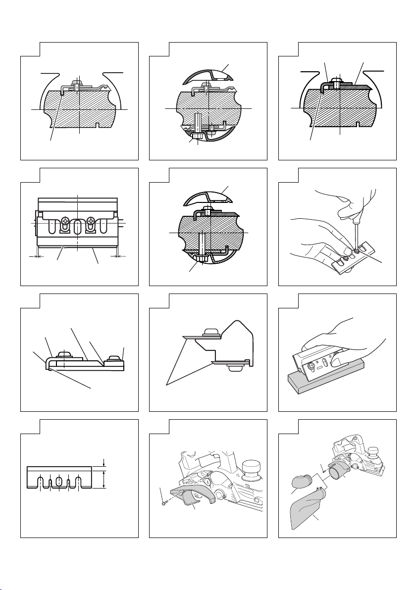
rÁllvány Stojan Stand Suport
tBeállító csavar Stavνcí šroub Ayar vidasıȘurub de reglare
yVezetőVodítko Kılavuz Ghidaj
uCsőkulcs Nástrčný klíčLokma anahtarıCheie tubularΣ
iKéstartó Držák čepele Bıçak tutucu Suport de lamΣ
oKarbid kés
(kétélűkéstípus)
Čepel s tvrdokovovým břitem
(typ dvoubřité čepele)
Karbür bıçak
(Çift kenarlıbıçak tipi)
LamΣdin carburΣ
(tip de lamΣcu douΣtΣişuri)
pVezetőlap (B) Stavνcí destička (B) Ayar plakası(B) PlacΣde fixare (B)
aRögzítőcsavar Šroub Cıvata Şurub
sGépcsavar Strojní šroub Makine vidasıŞurub mecanic
dÍves felület Zahnutá plocha Tornalanmışyüzey Suprafaţa prelucratΣ
fVezetőlap (A) Stavνcí destička (A) Ayar plakası(A) PlacΣde fixare (A)
gBeállító mérce Nastavovací mνrka Ayar mastarıEtalon pentru reglare
h„b” falfelület Povrch stνny b Duvar yüzeyi b Suprafaţa b a peretelui
jA vágó blokk sík része Plochá část řezného bloku Kesici bloğun düz kısmıPorţiunea planΣa blocului
de tΣiere
kHorony Drážka Oluk CanelurΣ
lKés
(újraélezhetőkéstípus) Čepel
(typ, který lze znovu ostřit)
Bıçak
(Yeniden bilenebilir bıçak tipi)
LamΣ
(tip de lamΣreprofilabilΣ)
;Vágó blokk Řezný blok Kesici blok Bloc de tΣiere
z„a” falfelület Povrch stνny a Duvar yüzeyi a Suprafaţa a peretelui
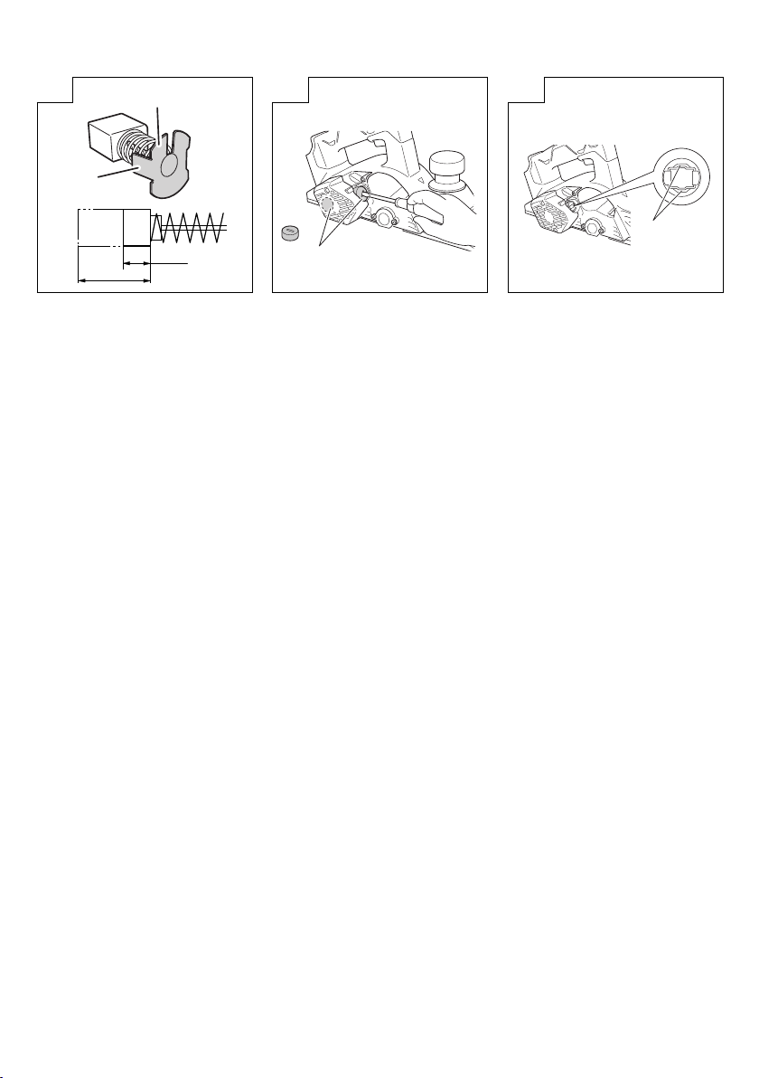
xForgácsfedél Hoblinový kryt TalaşkapağıApΣrΣtoare contra aşchiilor
cCsavar D4×16 Šroub D4×16 Vida D4×16 Şurub D4×16
vPor adapter Prachový adaptér Toz adaptörü Manşon de colectare a
prafului
000BookP14DSLEE.indb8000BookP14DSLEE.indb82014/01/2216:14:482014/01/2216:14:48

9
Magyar Čeština Türkçe RomânΣ
bKönyök Zahnutý díl Dirsek Tub cotit
nPorzsák Prachový vak Toz torbasıSac pentru praf
mKopási határ Limit opotřebení Aşınma sınırıLimita de uzurΣ
,A szénkefe szöge Cvoček uhlíkového
kartáčku Kömür çivisi Cuiul periei de cΣrbune
.A szénkefe kinyúlása Vodící lamely uhlíkového
kartáčeKarbon fırça çıkıntısıExtensie perie cΣrbune
/Kefe sapka Krytka kartáčů motoru Fırça kapağıCapac perie
¡Érintkezőrész a szénkefe
csövén kívül Dotyková část mimo
trubičku kartáčku Kömür tüpünün dışındaki
temas bölümü Porţiune de contact în
exteriorul tubului periei
000BookP14DSLEE.indb9000BookP14DSLEE.indb92014/01/2216:14:482014/01/2216:14:48

10
Slovenščina Slovenčina Pycc
1Oblanje Hobľovanie
2
Robljenje Úkos
3Zgibanje Drážkovanie
4Poševno odrezovanje Zahrotenie
5Baterija, ki se polni Nabíjateľný akumulátor
6Zapah Západka cap
7Baterijski pokrov Kryt akumulátora
8Sponke Koncovky
9Ventilacijske odprtine Vetracie otvory Be
0Pritisnite Stlačiť Haa
!Izvlecite Vytiahnuť Ba
@Ročica Rukoväť Pya
#Polnilec Nabíjačka
$Kontrolni svetlobni
indikator Kontrolný indikátor
%Zapora stikala Poistka spínača
^Sprožilec stikala Spúšťspínača
&Stikalo indikatorja za
preostalo baterijo
Spínačindikátora
zostávajúcej úrovne nabitia
batérie
*Lučka indikatorja preostale
energije baterije Indikátor zostávajúcej
kapacity akumulátora І
(Gumb Otočný regulátor
)Skala Mierka
qOznaka Značka
wZačetek oblanja Začatie rezania
eKonec oblanja Koniec rezania
rStojalo Stojan
tNastavitveni vijak Nastavovacia skrutka
yVodilo Vodiaci prvok
uNasadni ključZakladací kľúč
iDržalo rezila Držiak čepele
oKarbidno rezilo
(dvorezni tip rezila) Karbidová čepeľ
(obojstranný typ čepele)
()
()
pNastavitvena plošča (B) Nastavovacia platňa (B)
(B)
(B)
aVijak Skrutka
sStrojni vijak Skrutka so šesťhrannou
hlavou
dObrnjena površina Osústružená plocha
fNastavitvena plošča (A) Nastavovacia platňa (A)
(A)
(A)
gNastavitveni merilnik Nastavovacia mierka
hPovršina stene b Stenová plocha b b b
jPloščat del rezalnega
bloka Plochá časťhlavy noža
000BookP14DSLEE.indb10000BookP14DSLEE.indb102014/01/2216:14:482014/01/2216:14:48

11
Slovenščina Slovenčina Pycc
kUtor Drážka
l
Rezilo
(tip rezila, ki ga je mogoče
ostriti)
Čepeľ
(brúsiteľný typ čepele)
( )
()
;Rezalni blok Hlava noža
zPovršina zidu a Stenová plocha a a
xPokrov ostružkov Ochranný kryt proti
úlomkom
cVijak D4×16 Skrutka D4×16 D4×16 D4×16
vAdapter za prah Prachový adaptér
bKoleno Koleno
nVrečka za prah Vrecko na prach
mMeja obrabe Limit opotrebovania
,Zob grafitne krtačke Hrot uhlíkovej kefky
.Rob grafitne ščetke Výčnelok uhlíkovej kefky
/Pokrov ščetke Kryt kefky
¡Stični dekež izven cevi
ščetke Časťkontaktu mimo
uhlíkovej kefy
000BookP14DSLEE.indb11000BookP14DSLEE.indb112014/01/2216:14:482014/01/2216:14:48

12
English Deutsch η Polski
Symbols
WARNING
The following show
symbols used for the
machine. Be sure that you
understand their meaning
before use.
Symbole
WARNUNG
Die folgenden Symbole
werden für diese Maschine
verwendet. Achten Sie
darauf, diese vor der
Verwendung zu verstehen.
α
Π
χ
ύ
χηύ
ηχη.
η η
η χη.
Symbole
OSTRZEŻENIE
Następujące oznaczenia
to symbole używane w
instrukcji obsługi maszyny.
Upewnij się, że rozumiesz
ich znaczenie zanim
użyjesz narzędzia.
Read all safety
warnings and all
instructions.
Failure to follow
the warnings and
instructions may result in
electric shock, fire and/
or serious injury.
Lesen Sie sämtliche
Sicherheitshinweise und
Anweisungen durch.
Wenn die Warnungen
und Anweisungen nicht
befolgt werden, kann es
zu Stromschlag, Brand
und/oder ernsthaften
Verletzungen kommen.
αάτ τ
ααία α τ
ηί.
η ηη
ηώ
ηη,
/ .
Należy dokładnie zapoznać
sięze wszystkimi
ostrzeżeniami i wskazówkami
bezpieczeństwa.
Nieprzestrzeganie ostrzeżeń
oraz wskazówek bezpieczeństwa
może spowodowaćporażenie
prądem elektrycznym, pożar i/lub
odniesienie poważnych obrażeń.
Only for EU countries
Do not dispose of electric
tools together with
household waste material!
In observance of European
Directive 2002/96/EC
on waste electrical and
electronic equipment
and its implementation in
accordance with national
law, electric tools that have
reached the end of their life
must be collected separately
and returned to an
environmentally compatible
recycling facility.
Nur für EU-Länder
Werfen Sie
Elektrowerkzeuge nicht in
den Hausmüll!
Gemäss Europäischer
Richtlinie 2002/96/
EG über Elektro- und
Elektronik- Altgeräte
und Umsetzung in
nationales Recht
müssen verbrauchte
Elektrowerkzeuge
getrennt gesammelt und
einer umweltgerechaten
Wiederververtung
zugeführt werden.
χώ η
η η
ώ !
ύ η
ϊ η 2002/
96/ ηώ
ηώ ώ
η
η ,
η
χ
ύη
.
Dotyczy tylko państw UE
Nie wyrzucaj
elektronarzędzi wraz z
odpadami z gospodarstwa
domowego!
Zgodnie z Europejską
Dyrektywą2002/96/WE w
sprawie zużytego sprzętu
elektrotechnicznego i
elektronicznego oraz
dostosowaniem jej
do prawa krajowego,
zużyte elektronarzędzia
należy posegregować
i zutylizowaćw sposób
przyjazny dla środowiska.
n0no-load speed Leerlaufdrehzahl χύη χ
prędkość bez obciążenia
/min or min-1 Revolutions or
reciprocations per
minute
Umdrehungen oder
Pendelbewegungen pro
Minute
Obroty lub suwy na
minutę
Direct current Gleichstrom χ ύ Prąd stały
Caution Achtung χ Ostrzeżenie
VVolts Volt B Wolty
kg Kilograms Kilogramm X Kilogramy
000BookP14DSLEE.indb12000BookP14DSLEE.indb122014/01/2216:14:482014/01/2216:14:48

13
Magyar Čeština Türkçe RomânΣ
Jelölések
FIGYELEM
Az alábbiakban a
géphez alkalmazott
jelölések vannak
felsorolva. A gép
használata előtt
feltétlenül ismerje meg
ezeket a jelöléseket.
Symboly
UPOZORNĚNÍ
Následující text
obsahuje symboly, které
jsou použity na zařízení.
Ujistνte se, že rozumíte
jejich obsahu před tím,
než začnete zařízení
používat.
Simgeler
DхKKAT
Aşağıda, bu alet için
kullanılan simgeler
gösterilmiştir. Aleti
kullanmadan önce bu
simgelerin ne anlama
geldiğini anladığınızdan
emin olun.
Simboluri
AVERTISMENT
În cele ce urmeazΣsunt
prezentate simbolurile
folosite pentru mașinΣ.
Înainte de utilizare,
asiguraţi-vΣcΣînţelegeţi
semnificaţia acestora.
Olvasson el
minden biztonsági
figyelmeztetést és
minden utasítást.
A figyelmeztetések
és utasítások be nem
tartása áramütést, tüzet
és/vagy súlyos sérülést
eredményezhet.
Přečtνte si všechna
varování týkající
se bezpečnosti a
všechny pokyny.
Nedodržení tνchto
varování a pokynů
může mít za následek
elektrický šok, požár a/
nebo vážné zranνní.
Tüm güvenlik
uyarılarınıve tüm
talimatlarıokuyun.
Uyarılara ve talimatlara
uyulmamasıelektrik
çarpmasına, yangına ve/
veya ciddi yaralanmaya
neden olabilir.
Citiţi toate avertismentele
privind siguranţa și toate
instrucţiunile.
Nerespectarea
avertismentelor și a
instrucţiunilor poate avea ca
efect producerea de șocuri
electrice, incendii și/sau
vΣtΣmΣri grave.
Csak EU-országok
számára
Az elektromos
kéziszerszámokat
ne dobja a háztartási
szemétbe!
A használt villamos
és elektronikai
készülékekről szóló
2002/96/EK irányelv és
annak a nemzeti jogba
való átültetése szerint az
elhasznált elektromos
kéziszerszámokat
külön kell gyűjteni, és
környezetbarát módon
újra kell hasznosítani.
Jen pro státy EU
Elektrické nářadí
nevyhazujte do
komunálního odpadu!
Podle evropské
smνrnice 2002/96/
EG o nakládání s
použitými elektrickými
a elektronickými
zařízeními a
odpovídajících
ustanovení právních
předpisůjednotlivých
zemí se použitá
elektrická nářadí musí
sbírat oddνlenνod
ostatního odpadu a
podrobit ekologicky
šetrnému recyklování.
Sadece AB ülkeleri için
Elektrikli el aletlerini
evdeki çöp kutusuna
atmayınız!
Kullanılmışelektrikli
aletleri, elektrik ve
elektronikli eski cihazlar
hakkındaki 2002/96/EC
Avrupa yönergelerine
göre ve bu yönergeler
ulusal hukuk kurallarına
göre uyarlanarak, ayrı
olarak toplanmalıve
çevre şartlarına uygun
bir şekilde tekrar
değerlendirmeye
gönderilmelidir.
Numai pentru ţΣrile membre UE
Nu aruncaţi aceastΣsculΣ
electricΣîmpreunΣcu deșeurile
menajere!
În conformitate cu Directiva
EuropeanΣ2002/96/CE
referitoare la deșeurile
reprezentând echipamente
electrice și electronice și la
implementarea acesteia în
conformitate cu legislaţiile
naţionale, sculele electrice
care au ajuns la finalul duratei
de folosire trebuie colectate
separat și duse la o unitate de
reciclare compatibilΣcu mediul
înconjurΣtor.
n0
terhelés nélküli sebesség
otáčky bez zátνže yüksüz hız turaţie fΣrΣsarcinΣ
/min or min-1 Percenkénti fordulat-
vagy ismétlődésszám Otáčky nebo střídání za
minutu Dakika başına dönüş
veya ileri geri hareket Rotaţii pe minut
Egyenáram Stejnosmνrný proud Doğru akım Curent continuu
Vigyázat Upozornνní Dikkat Atenţie
VVolt Volty Volt Volţi
kg Kilogramm Kilogramy Kilogram Kilograme
000BookP14DSLEE.indb13000BookP14DSLEE.indb132014/01/2216:14:482014/01/2216:14:48

14
Slovenščina Slovenčina Pycc
Simboli
OPOZORILO
V nadaljevanju so
prikazani simboli,
uporabljeni pri stroju.
Pred uporabo se
prepričajte, da jih
razumete.
Symboly
VÝSTRAHA
V nasledujúcom sú
zobrazené symboly, ktoré
sú vyobrazené na náradí.
Pred použitím náradia sa
oboznámte s významom
týchto symbolov.
,
. ,
,
є є
.
ы
,
.
,
.
Preberite vas
varnostna opozorila in
navodila.
Z neupoštevanjem
opozoril in navodil
tvegate električni udar,
požar in/ali resne
telesne poškodbe.
Prečítajte si všetky
bezpečnostné výstrahy a
všetky pokyny.
Nedodržanie výstrah a
pokynov môže viesťk
zasiahnutiu elektrickým
prúdom, požiaru a/alebo
vážnemu poraneniu osoby.
р
р
.
,
/
.
р р
р.
,
/
.
Samo za države EU
Električnih orodij
ne zavržite skupaj z
gospodinjskimi odpadki!
V skladu z evropsko
direktivo 2002/96/EC
o odpadni električni
in elektronski opremi
in izvedbi v skladu z
državnimi zakoni, je
treba električna orodja,
ki so dosegla življenjsko
dobo ločeno zbirati
in vrniti v z okoljem
združljivo ustanovo za
recikliranje.
Iba pre krajiny EÚ
Elektrické náradie
nezneškodňujte spolu s
komunálnym odpadom z
domácností!
Aby ste dodržali ustanovenia
európskej smernice 2002/96/
ES o odpadových elektrických
a elektronických zariadeniach
a jej implementáciu v zmysle
národnej legislatívy, je
potrebné elektrické zariadenie
po uplynutí jeho doby
životnosti separovaťa doručiť
na environmentálne prijateľné
miesto recyklovania.
Є
!
Є
2002/96/EC
,
,
,
.
!
2002/96/
,
,
.
n0
Hitrost brez obremenitve
voľnobežné otáčky
/min or min-1 Obratov ali gibov na
minuto Otáčky alebo pohyby za
minútu
Enosmerni tok Jednosmerný prúd
Pozor Upozornenie
VVolti Volty
kg Kilogrami Kilogramy
000BookP14DSLEE.indb14000BookP14DSLEE.indb142014/01/2216:14:482014/01/2216:14:48

English
15
GENERAL POWER TOOL SAFETY WARNINGS
WARNING
Read all safety warnings and all instructions.
Failure to follow the warnings and instructions may result in
electric shock, fire and/or serious injury.
Save all warnings and instructions for future reference.
The term “power tool” in the warnings refers to your mains-
operated (corded) power tool or battery-operated (cordless)
power tool.
1) Work area safety
a) Keep work area clean and well lit.
Cluttered or dark areas invite accidents.
b) Do not operate power tools in explosive
atmospheres, such as in the presence of
flammable liquids, gases or dust.
Power tools create sparks which may ignite the dust
or fumes.
c) Keep children and bystanders away while
operating a power tool.
Distractions can cause you to lose control.
2) Electrical safety
a) Power tool plugs must match the outlet.
Never modify the plug in any way.
Do not use any adapter plugs with earthed
(grounded) power tools.
Unmodified plugs and matching outlets will reduce
risk of electric shock.
b) Avoid body contact with earthed or grounded
surfaces, such as pipes, radiators, ranges and
refrigerators.
There is an increased risk of electric shock if your
body is earthed or grounded.
c) Do not expose power tools to rain or wet
conditions.
Water entering a power tool will increase the risk of
electric shock.
d) Do not abuse the cord. Never use the cord for
carrying, pulling or unplugging the power tool.
Keep cord away from heat, oil, sharp edges or
moving parts.
Damaged or entangled cords increase the risk of
electric shock.
e) When operating a power tool outdoors, use an
extension cord suitable for outdoor use.
Use of a cord suitable for outdoor use reduces the
risk of electric shock.
f) If operating a power tool in a damp location
is unavoidable, use a residual current device
(RCD) protected supply.
Use of an RCD reduces the risk of electric shock.
3) Personal safety
a) Stay alert, watch what you are doing and use
common sense when operating a power tool.
Do not use a power tool while you are tired
or under the influence of drugs, alcohol or
medication.
A moment of inattention while operating power tools
may result in serious personal injury.
b) Use personal protective equipment. Always wear
eye protection.
Protective equipment such as dust mask, non-skid
safety shoes, hard hat, or hearing protection used for
appropriate conditions will reduce personal injuries.
c) Prevent unintentional starting. Ensure the
switch is in the off-position before connecting to
power source and/or battery pack, picking up or
carrying the tool.
Carrying power tools with your finger on the switch or
energising power tools that have the switch on invites
accidents.
d) Remove any adjusting key or wrench before
turning the power tool on.
A wrench or a key left attached to a rotating part of the
power tool may result in personal injury.
e) Do not overreach. Keep proper footing and
balance at all times.
This enables better control of the power tool in
unexpected situations.
f) Dress properly. Do not wear loose clothing or
jewellery. Keep your hair, clothing and gloves
away from moving parts.
Loose clothes, jewellery or long hair can be caught in
moving parts.
g) If devices are provided for the connection of
dust extraction and collection facilities, ensure
these are connected and properly used.
Use of dust collection can reduce dust related hazards.
4) Power tool use and care
a) Do not force the power tool. Use the correct
power tool for your application.
The correct power tool will do the job better and safer
at the rate for which it was designed.
b) Do not use the power tool if the switch does not
turn it on and off.
Any power tool that cannot be controlled with the
switch is dangerous and must be repaired.
c) Disconnect the plug from the power source and/
or the battery pack from the power tool before
making any adjustments, changing accessories,
or storing power tools.
Such preventive safety measures reduce the risk of
starting the power tool accidentally.
d) Store idle power tools out of the reach of children
and do not allow persons unfamiliar with the
power tool or these instructions to operate the
power tool.
Power tools are dangerous in the hands of untrained
users.
e) Maintain power tools. Check for misalignment or
binding of moving parts, breakage of parts and
any other condition that may affect the power
tools’ operation.
If damaged, have the power tool repaired before
use.
Many accidents are caused by poorly maintained
power tools.
f) Keep cutting tools sharp and clean.
Properly maintained cutting tools with sharp cutting
edges are less likely to bind and are easier to
control.
g) Use the power tool, accessories and tool bits
etc. in accordance with these instructions,
taking into account the working conditions and
the work to be performed.
Use of the power tool for operations different from those
intended could result in a hazardous situation.
5) Battery tool use and care
a) Recharge only with the charger specified by the
manufacturer.
A charger that is suitable for one type of battery pack
may create a risk of fire when used with another
battery pack.
b) Use power tools only with specifically designated
battery packs.
Use of any other battery packs may create a risk of
injury and fire.
(Original instructions)
000BookP14DSLEE.indb15000BookP14DSLEE.indb152014/01/2216:14:482014/01/2216:14:48

English
16
c) When battery pack is not in use, keep it away
from other metal objects like paper clips, coins,
keys, nails, screws, or other small metal objects
that can make a connection from one terminal to
another.
Shorting the battery terminals together may cause
burns or a fire.
d) Under abusive conditions, liquid may be ejected
from the battery; avoid contact. If contact
accidentally occurs, flush with water. If liquid
contacts eyes, additionally seek medical help.
Liquid ejected from the battery may cause irritation or
burns.
6) Service
a) Have your power tool serviced by a qualified
repair person using only identical replacement
parts.
This will ensure that the safety of the power tool is
maintained.
PRECAUTION
Keep children and infirm persons away.
When not in use, tools should be stored out of reach of
children and infirm persons.
CORDLESS PLANER SAFETY WARNINGS
1. Wait for the cutter to stop before settling the tool
down.
An exposed rotating cutter may engage the surface
leading to possible loss of control and serious injury.
2. Use clamps or another practical way to secure and
support the workpiece to a stable platform.
Holding the work by your hand or against the body leaves
it unstable and may lead to loss of control.
3. Do not use the Planer with the blades facing upward (as
stationary type planer).
4. Always charge the battery at a temperature of 0 – 40°C.
A temperature of less than 0°C will result in over charging
which is dangerous. The battery cannot be charged at a
temperature greater than 40°C.
The most suitable temperature for charging is that of 20 –
25°C.
5. Do not use the charger continuously.
When one charging is completed, leave the charger for
about 15 minutes before the next charging of battery.
6. Do not allow foreign matter to enter the hole for
connecting the rechargeable battery.
7. Never disassemble the rechargeable battery and
charger.
8. Never short-circuit the rechargeable battery.
Short-circuiting the battery will cause a great electric
current and overheat. It results in burn or damage to the
battery.
9. Do not dispose of the battery in fire.
If the battery burnt, it may explode.
10. Do not insert object into the air ventilation slots of the
charger.
Inserting metal objects or inflammables into the charger
air ventilation slots will result in electrical shock hazard or
damaged charger.
11. Bring the battery to the shop from which it was purchased
as soon as the post-charging battery life becomes too
short for practical use. Do not dispose of the exhausted
battery.
12. Using an exhausted battery will damage the charger.
CAUTION ON LITHIUM-ION BATTERY
To extend the lifetime, the lithium-ion battery equips with the
protection function to stop the output.
In the cases of 1 to 3 described below, when using this
product, even if you are pulling the switch, the motor may
stop. This is not the trouble but the result of protection
function.
1. When the battery power remaining runs out, the motor
stops.
In such case, charge it up immediately.
2. If the tool is overloaded, the motor may stop. In this
case, release the switch of tool and eliminate causes of
overloading. After that, you can use it again.
3. If the battery is overheated under overload work, the
battery power may stop.
In this case, stop using the battery and let the battery
cool. After that, you can use it again.
Furthermore, please heed the following warning and caution.
WARNING
In order to prevent any battery leakage, heat generation,
smoke emission, explosion and ignition beforehand, please
be sure to heed the following precautions.
1. Make sure that swarf and dust do not collect on the
battery.
◯During work make sure that swarf and dust do not fall on
the battery.
◯Make sure that any swarf and dust falling on the power
tool during work do not collect on the battery.
◯Do not store an unused battery in a location exposed to
swarf and dust.
◯Before storing a battery, remove any swarf and dust that
may adhere to it and do not store it together with metal
parts (screws, nails, etc.).
2. Do not pierce battery with a sharp object such as a
nail, strike with a hammer, step on, throw or subject the
battery to severe physical shock.
3. Do not use an apparently damaged or deformed battery.
4. Do not use the battery in reverse polarity.
5. Do not connect directly to an electrical outlets or car
cigarette lighter sockets.
6. Do not use the battery for a purpose other than those
specified.
7. If the battery charging fails to complete even when a
specified recharging time has elapsed, immediately stop
further recharging.
8. Do not put or subject the battery to high temperatures or
high pressure such as into a microwave oven, dryer, or
high pressure container.
9. Keep away from fire immediately when leakage or foul
odor are detected.
10. Do not use in a location where strong static electricity
generates.
11. If there is battery leakage, foul odor, heat generated,
discolored or deformed, or in any way appears abnormal
during use, recharging or storage, immediately remove it
from the equipment or battery charger, and stop use.
CAUTION
1. If liquid leaking from the battery gets into your eyes, do not
rub your eyes and wash them well with fresh clean water
such as tap water and contact a doctor immediately.
If left untreated, the liquid may cause eye-problems.
2. If liquid leaks onto your skin or clothes, wash well with
clean water such as tap water immediately.
There is a possibility that this can cause skin irritation.
3. If you find rust, foul odor, overheating, discolor,
deformation, and/or other irregularities when using the
battery for the first time, do not use and return it to your
supplier or vendor.
000BookP14DSLEE.indb16000BookP14DSLEE.indb162014/01/2216:14:482014/01/2216:14:48

English
17
WARNING
If an electrically conductive foreign object enters the terminals
of the lithium ion battery, a short-circuit may occur resulting
in the risk of fire. Please observe the following matters when
storing the battery.
◯Do not place electrically conductive cuttings, nails,
steel wire, copper wire or other wire in the storage
case.
SPECIFICATIONS
POWER TOOL
Model P14DSL P18DSL
Cutting Width 82 mm
Max. Cutting Depth 2.0 mm
No-load speed 16000 min-1
Rechargeable
battery
2LSRK BSL1430: Li-ion 14.4 V (3.0 Ah 8 cells)
BSL1830: Li-ion 18 V (3.0 Ah 10 cells)
2LJRK
BSL1450: Li-ion 14.4 V (5.0 Ah 8 cells) BSL1850: Li-ion 18 V (5.0 Ah 10 cells)
Weight
* 3.2 kg (With BSL1430) 3.3 kg (With BSL1830)
* Weight: According to EPTA-Procedure 01/2003
CHARGER
Model UC18YFSL
Charging voltage 14.4 V – 18 V
Weight 0.5 kg
STANDARD ACCESSORIES
In addition to the main unit (1), the package contains the
accessories listed in the table below.
P14DSL
(2LSRK)
(2LJRK)
P18DSL
(2LSRK)
(2LJRK)
1 Box Wrench............................................ 1
(for securing cutter blade)
2 Set Gauge .............................................. 1
(for adjusting cutter height)
3 Guide......................................................1
(with set screw)
4 Carbide Blade ........................................2
(Double edged Blade type)
5 Charger ..................................................1
6 Battery.................................................... 2
[P14DSL] BSL1430 or BSL1450
[P18DSL] BSL1830 or BSL1850
7 Plastic case ............................................ 1
8 Battery cover .......................................... 2
9 Spare carbide Blade set.........................1
(Not supplied in all areas)
P14DSL (NN)
P18DSL (NN)
1 Box Wrench............................................ 1
(for securing cutter blade)
2 Set Gauge .............................................. 1
(for adjusting cutter height)
3 Guide......................................................1
(with set screw)
4 Carbide Blade ........................................2
(Double edged Blade type)
Without chager, battery, plastic case and
battery cover.
Standard accessories are subject to change without notice.
◯Either install the battery in the power tool or store
by securely pressing into the battery cover until the
ventilation holes are concealed to prevent short-
circuits (See Fig. 5).
OPTIONAL ACCESSORIES (sold separately)
(BSL1430)
(BSL1440)
(BSL1450)
(BSL1830)
(BSL1840)
(BSL1850)
1. Battery
5. Carbide Blade
(Double edged Blade
type)
6. Blade
(Resharpenable blade
type)
2. Dust adapter 3. Elbow 4. Dust bag
Optional accessories are subject to change without notice.
APPLICATIONS
Planing various wooden planks and panels. (See Fig. 1-4)
000BookP14DSLEE.indb17000BookP14DSLEE.indb172014/01/2216:14:482014/01/2216:14:48

English
18
BATTERY REMOVAL/INSTALLATION
1. Battery removal
Hold the handle tightly and push the battery latch to
remove the battery (see Figs. 5 and 6).
CAUTION
Never short-circuit the battery.
2. Battery installation
Insert the battery while observing its polarities (see
Fig. 6).
CHARGING
Before using the power tool, charge the battery as follows.
1. Connect the charger's power cord to the receptacle.
When the power cord is connected, the charger’s pilot
lamp will blink in red. (At 1-second intervals)
CAUTION
Do not use the electrical cord if damaged. Have it
repaired immediately.
2. Insert the battery into the charger.
Firmly insert the battery into the charger, as shown in
Fig. 7.
3. Charging
When inserting a battery in the charger, charging will
commence and the pilot lamp will light continuously in
red.
When the battery becomes fully recharged, the pilot lamp
will blink in red. (At 1-second intervals) (See Table 1)
(1) Pilot lamp indication
The indications of the pilot lamp will be as shown in
Table 1, according to the condition of the charger or the
rechargeable battery.
Table 1
Indications of the pilot lamp
Pilot lamp
(red)
Before
charging Blinks Lights for 0.5 seconds. Does not light
for 0.5 seconds. (offfor 0.5 seconds)
While
charging Lights Lights continuously
Charging
complete Blinks Lights for 0.5 seconds. Does not light
for 0.5 seconds. (offfor 0.5 seconds)
Overheat
standby Blinks
Lights for 1 second. Does not light
for 0.5 seconds. (offfor 0.5 seconds) Battery overheated.
Unable to charge.
(Charging will commence
when battery cools)
Charging
impossible Flickers Lights for 0.1 seconds. Does not light for
0.1 seconds. (offfor 0.1 seconds) Malfunction in the battery
or the charger
(2) Regarding the temperatures of the rechargeable battery
The temperatures for rechargeable batteries are as
shown in Table 2, and batteries that have become hot
should be cooled for a while before being recharged.
Table 2 Recharging ranges of batteries
Rechargeable batteries Temperatures at
which the battery
can be recharged
BSL1430, BSL1440, BSL1450,
BSL1820, BSL1830, BSL1840,
BSL1850 0°C – 40°C
(3) Regarding recharging time
Depending on the combination of the charger and
batteries, the charging time will become as shown in
Table 3.
Table 3 Charging time (At 20°C)
Charger
Battery UC18YFSL
BSL1820 Approx. 30 min.
BSL1430, BSL1830 Approx. 45 min.
BSL1440, BSL1840 Approx. 60 min.
BSL1450, BSL1850 Approx. 75 min.
NOTE
The charging time may vary according to temperature
and power source voltage.
CAUTION
When the battery charger has been continuously used,
the battery charger will be heated, thus constituting
the cause of the failures. Once the charging has been
completed, give 15 minutes rest until the next charging.
4. Disconnect the charger’s power cord from the
receptacle.
5. Hold the charger firmly and pull out the battery.
NOTE
Be sure to pull out the battery from the charger after use,
and then keep it.
How to make the batteries perform longer
(1) Recharge the batteries before they become completely
exhausted.
When you feel that the power of the tool becomes
weaker, stop using the tool and recharge its battery. If
you continue to use the tool and exhaust the electric
current, the battery may be damaged and its life will
become shorter.
(2) Avoid recharging at high temperatures.
A rechargeable battery will be hot immediately after use.
If such a battery is recharged immediately after use, its
internal chemical substance will deteriorate, and the
battery life will be shortened. Leave the battery and
recharge it after it has cooled for a while.
000BookP14DSLEE.indb18000BookP14DSLEE.indb182014/01/2216:14:482014/01/2216:14:48

English
19
CAUTION
○If the battery is charged while it is heated because it has
been left for a long time in a location subject to direct
sunlight or because the battery has just been used, the
pilot lamp of the charger lights for 1 second, does not
light for 0.5 seconds (offfor 0.5 seconds). In such a case,
first let the battery cool, then start charging.
○When the pilot lamp flickers in red (at 0.2-seconds
intervals), check for and take out any foreign objects in
the charger’s battery connector. If there are no foreign
objects, it is probable that the battery or charger is
malfunctioning. Take it to your authorized Service
Center.
○Since the built-in micro computer takes about 3
seconds to confirm that the battery being charged with
UC18YFSL is taken out, wait for a minimum of 3 seconds
before reinserting it to continue charging. If the battery
is reinserted within 3 seconds, the battery may not be
properly charged.
○If the pilot lamp does not blink in red (every second) even
though the charger cord is connected to the power, it
indicates that the protection circuit of the charger may be
activated.
Remove the cord from the power and then connect it
again after 30 seconds or so. If this does not cause the
pilot lamp to blink in red (every second), please take the
charger to the Hitachi Authorized Service Center.
PRIOR TO OPERATION
1. Setting up and checking the work environment
Check if the work environment is suitable by following the
precautions.
2. Power switch
Ensure that the power switch is in the OFF position. If the
battery is attached to the body while the power switch
is in the ON position, the power tool will start operating
immediately, which could cause a serious accident.
3. Prepare a stable wooden workbench suitable for
planning operation. As a poorly balanced workbench
creates a hazard, ensure it is securely positioned on firm,
level ground.
PLANING PROCEDURES
1. Operation of switch (Fig. 8)
(1) For safe operation of the machine, a “switch lock” is
provided on the side of a handle.
If the “switch trigger” is pulled in a state where “switch
lock” is pressed in the direction of the arrow mark, the
main switch can be turned ON.
(2) After the switch is turned ON, even when you release
your hand from the switch lock, the body continues
running and the light continues being turned ON as long
as you keep on pulling the switch trigger.
(3) If you release the switch trigger, you can turn OFF the
switch and the “switch lock” returns to the original
position automatically.
CAUTION
Do not fix and secure the switch lock. Besides, keep
your finger offthe switch trigger when the planer is
being carried around. Otherwise, the main body switch
can be inadvertently turned ON, resulting in unexpected
accidents.
2. About remaining battery indicator
When pressing the remaining battery indicator switch,
the remaining battery indicator lamp lights and the
battery remaining power can be checked. (Fig. 9)
When releasing your finger from the remaining battery
indicator switch, the remaining battery indicator lamp
goes off. The Table 4 shows the state of remaining
battery indicator lamp and the battery remaining power.
Table 4
State of lamp Battery Remaining Power
The battery remaining power is enough.
The battery remaining power is a half.
The battery remaining power is nearly
empty.
Re-charge the battery soonest possible.
As the remaining battery indicator shows somewhat
differently depending on ambient temperature and battery
characteristics, read it as a reference.
NOTE
◯Do not give a strong shock to the switch panel or break it.
It may lead to a trouble.
◯To save the battery power consumption, the remaining
battery indicator lamp lights while pressing the remaining
battery indicator switch.
3. Adjusting the cutter depth
(1) Turn the knob in the direction indicated by the arrow in
Fig. 10 (clockwise), until the triangular mark is aligned
with the desired cutting depth on the scale. The scale unit
is graduated in millimeters.
(2) The cutting depth can be adjusted within a range of 0-2.0
mm.
4. Surface cutting
Rough cutting should be accomplished at large cutting
depths and at a suitable speed so that shavings are
smoothly ejected from the machine.
To ensure a smoothly finished surface, finish cutting
should be accomplished at small cutting depths and at
low feeding speed.
5. Beginning and ending the cutting operation
As shown in Fig. 11, place the front base of the planer on
the material and support the planer horizontally. Turn ON
the power switch, and slowly operate the planer toward
the leading edge of the material. Firmly depress the front
half of the planer at the first stage of cutting, as shown in
Fig. 12, depress the rear half of the planer at the end of
the cutting operation. The planer must always be kept flat
throughout the entire cutting operation.
6. Precaution after finishing the planing operation
When the planer is suspended with one hand after
finishing the planing operation, ensure that the cutting
blades (base) of the planer do not contact or come too
near your body. Failure to do so could result in serious
injury.
7. Stand
Lift the back of the planer to extend the foot from the
base. Having the stand extended when you put the
planer down prevents contact between the blade and the
material. (Fig. 13)
8. Regulating the guide (Fig. 14)
The planing position can be regulated by moving the
guide to the left or right after loosening its set screw. The
guide may be mounted on either the right or left side of
the tool.
000BookP14DSLEE.indb19000BookP14DSLEE.indb192014/01/2216:14:482014/01/2216:14:48

English
20
Work Precautions
◯About Continuous Operation
This tool is provided with a protective function to extend
battery life.
The battery may become overheated during continuous
operation or deep cutting operations, which may cause it
to automatically stop.
Especially with any of the batteries listed below, the tool
may stop operation before the battery starts to get hot to
prevent rapid failure from overheating.
If this happens, stop operation, remove the battery from
the tool and leave it in a well-ventilated location not
exposed to sunlight until it is sufficiently cool.
The battery can be used again once it is cool.
(Applicable batteries: BSL1425, BSL1420, BSL1415,
BSL1825, BSL1820, BSL1815 and old batteries)
◯Proper Battery Usage
When the tool is used with any of the batteries listed
below, it should be used for light work to extend battery
life.
Work example: Shallow depth finishing and chamfering
work
(Applicable batteries: BSL1425, BSL1420, BSL1415,
BSL1825, BSL1820, BSL1815 and old batteries)
CARBIDE BLADE ASSEMBLY AND
DISASSEMBLY AND ADJUSTMENT OF CUTTER
BLADE HEIGHT (FOR DOUBLE EDGED BLADE
TYPE)
1. Carbide blade disassembly
CAUTION
○To prevent accidents, ensure that the power tool is
switched offand pull out the battery.
○Be careful not to injure your hands.
(1) As shown in Fig. 15, loosen the blade holder with the
attached box wrench.
(2) As shown in Fig. 16, remove the carbide blade by sliding
it with the attached box wrench.
2. Carbide blade assembly
CAUTION
○To prevent accidents, ensure that the power tool is
switched offand pull out the battery.
○Prior to assembly, thoroughly wipe offall swarf
accumulated on the carbide blade.
(1) As shown in Fig. 17, lift set plate (B) and insert the new
carbide blade between cutter block and set plate (B).
(2) As shown in Fig. 18, mount the new carbide blade by
sliding it on the set plate (B) so that the blade tip projects
by 1mm from the end of the cutter block.
(3) As shown in Fig. 19, fix the bolts at the blade holder after
blade replacement has been completed.
(4) Turn the cutter block over, and set the other side in the
same manner.
3. Adjustment of carbide blade height
CAUTION
○To prevent accidents, ensure that the power tool is
switched offand pull out the battery.
○If the carbide blade’s heights are inaccurate after
above procedures have been completed, carry out the
procedures described below.
(1) As shown in Fig. 20, use the box wrench to loosen the
three bolts used to retain the carbide blade, and remove
the blade holder.
(2) As shown in Fig. 21, after removing the carbide blade,
slide set plate (B) in the direction indicated by the arrow
to disassemble set plate (B).
(3) Loosen the 2 screws holding on the carbide blade and
set plate (A), set plate (B).
(4) As shown in Fig. 22, 23, press the turned surface of set
plate (A) to the wall surface b while adjusting the carbide
blade edge to the wall surface a of the set gauge. Then,
tighten them with the 2 screws.
(5) As shown in Fig. 24, 25, insert a turned portion of set
plate (A) attached to set plate (B) into a groove on the flat
portion of the cutter block.
(6) As shown in Fig. 26, place the blade holder on the
completed assembly and fasten it with the three bolts.
Ensure that the bolts are securely tightened. Follow the
same procedures for the opposite side carbide blade.
BLADE ASSEMBLY AND DISASSEMBLY
AND ADJUSTMENT OF BLADE HEIGHT (FOR
RESHARPENABLE BLADE TYPE)
1. Blade disassembly
CAUTION
○To prevent accidents, ensure that the power tool is
switched offand pull out the battery.
○Be careful not to injure your hands.
(1) As shown in Fig. 20, use the accessory box wrench
to loosen the three bolts used to retain the blade, and
remove the blade holder.
(2) As shown in Fig. 21, slide the blade in the direction
indicated by the arrow to disassemble the blade.
2. Blade assembly
CAUTION
○To prevent accidents, ensure that the power tool is
switched offand pull out the battery.
○Prior to assembly, thoroughly wipe offall swarf
accumulated on the blade.
(1) Insert a turned portion of set plate (A) attached to the
blade into a groove on the flat portion of the cutter block.
(Fig. 24, 27)
Set the blade so that both sides of the blade protrude
from the width of the cutter block by about 1 mm (Fig. 28)
(2) Place the blade holder on the completed assembly,
as shown in Fig. 29, and fasten it with the three bolts.
Ensure that the bolts are securely tightened.
(3) Turn the cutter block over, and set the opposite side in
the same manner.
3. Adjustment of blade height
(1) Loosen the 2 screws holding on the blade and set plate
(A). (Fig. 30)
(2) Press the turned surface of set plate (A) to the wall surface
b while adjusting the blade edge to the wall surface a of
the set gauge. Then, tighten them with the 2 screws. (Fig.
22, 31)
SHARPENING THE RESHARPENABLE BLADES
Use of the accessory Blade Sharpening Ass'y is
recommended for convenience.
1. Use of Blade Sharpening Ass'y
As shown in Fig. 32, two blades can be mounted on the
blade sharpening ass'y to ensure that the blade tips are
ground at uniform angles. During grinding, adjust the
position of the blades so that their edges simultaneously
contact the dressing stone as shown in Fig. 33.
2. Blade sharpening intervals
Blade sharpening intervals depend on the type of wood
being cut and the cutting depth. However, sharpening
should generally be effected after each 500 meters of
cutting operation.
3. Grinding allowance of the cutter blades
As illustrated in Fig. 34, a grinding allowance of 3.5mm
is provided for on the cutter blade. That is, the cutter
blade can be repeatedly sharpened until its total height
is reduced to 24.5 mm.
000BookP14DSLEE.indb20000BookP14DSLEE.indb202014/01/2216:14:492014/01/2216:14:49
This manual suits for next models
2
Table of contents
Languages:
Other Hitachi Koki Planer manuals
Popular Planer manuals by other brands

GÜDE
GÜDE GAH 1300 Translation of the original instructions

Virutex
Virutex DUO CE223X operating instructions

Rikon Power Tools
Rikon Power Tools 23-400H Operator's manual

Parkside
Parkside PEH 30 A1 ELECTRIC PLANER Operation and safety notes

Carbatec
Carbatec TJ-X250C owner's manual

Delta
Delta 22-681 instruction manual