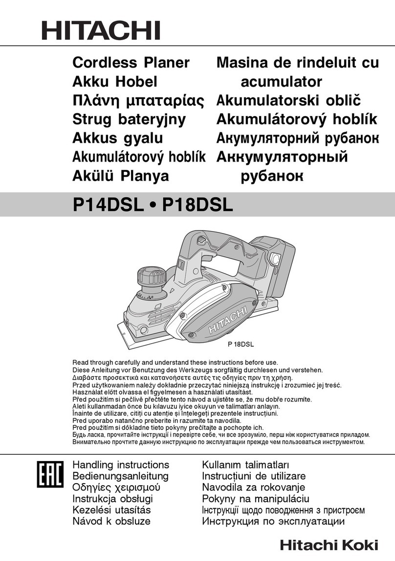
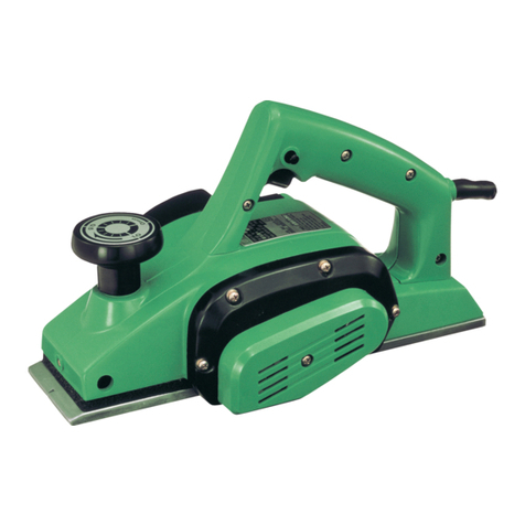
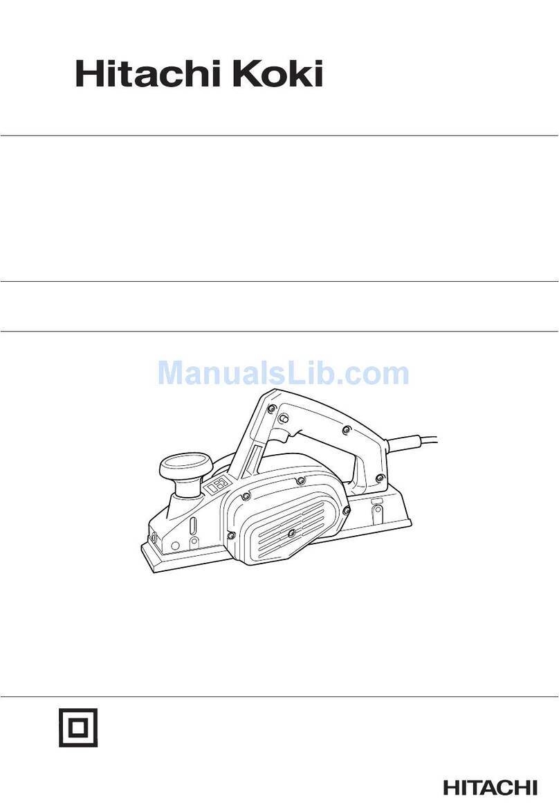
Hitachi Koki P 20ST User manual

Planer
電動鉋刀機
대패
Máy bào
Mesin Ketam
P 20ST
Read through carefully and understand these instructions before use.
使用前務請詳加閱讀
본 설명서를 자세히 읽고 내용을 숙지한 뒤 제품을 사용하십시오.
Đọc kỹvà hiểu rõ các hướng dẫn này trước khi sửdụng.
โปรดอ่านโดยละเอียดและทําความเข้าใจก่อนใช้งาน
Bacalah dengan cermat dan pahami petunjuk ini sebelum menggunakan perkakas.
Handling instructions
使用說明書
취급 설명서
Hướng dẫn sửdụng
คูมือการใชงาน
Petunjuk pemakaian
000BookP20STAsia.indb1000BookP20STAsia.indb1 2015/01/2618:14:142015/01/2618:14:14

82 mm (Max)
9 mm (Max)
9 mm (Max)
1 32
45
7
6
8
9
$
@
!
0
@
2
123
456
789
10 11 12
000BookP20STAsia.indb2000BookP20STAsia.indb2 2015/01/2618:14:152015/01/2618:14:15

1 mm1 mm
#%
!0
$
(
&
r
$@
^
*
&
)
#
q
!
q
&w
e
w
#
!
(
&r
w
^*!
0
#
t
3
13 14 15
16 17 18
19 20 21
22 23 24
000BookP20STAsia.indb3000BookP20STAsia.indb3 2015/01/2618:14:152015/01/2618:14:15

o
%
!
i
f
&
a
d
&s
w
g
u
y
p
%
4
25 26 27
28 29 30
31 32 33
34 35 36
000BookP20STAsia.indb4000BookP20STAsia.indb4 2015/01/2618:14:162015/01/2618:14:16

12 mm
5 mm
21
h
j
j
x
z
k
;
l
5
37 38 39
000BookP20STAsia.indb5000BookP20STAsia.indb5 2015/01/2618:14:162015/01/2618:14:16

6
English 中國語 한국어 Tiếng Việt
1Planing 鉋平 플레닝 Lập kếhoạch
2Beveling 斜削 베벨링 Cắt vát
3Rabbeting 嵌接 라베팅 Gấp (mép)
4Tapering 削尖 테이퍼링 Vuốt nhọn
5Knob 捏手 손잡이 Núm vặn
6Scale 刻度盤 스케일 Thang đo
7Mark 符號 표식 Ký hiệu
8Beginning of cutting
operation 切削起點 절삭 작업 시작 Bắt đầu thao tác bào
9End of cutting operation 切削終點 절삭 작업 종료 Kết thúc thao tác bào
0Box wrench 套筒板手 박스 렌치 Cờ-lê lỗ
!Blade holder 刀架 블레이드 홀더 Giá kẹp lưỡi dao
@Carbide blade
(Double edged blade type) 炭化刃(雙刃型) 카바이드 날(양날형) Dao cacbit (kiểu dao hai
cạnh sắc)
#Bolt 螺栓 볼트 Bu lông
$Set plate (B) 定位板(B) 세트 플레이트(B) Tấm chặn (B)
%Machine screw 機用螺釘 기계나사 Vít máy
^Turned surface 轉動面 선삭가공 표면 Bềmặt quay
&Set plate (A) 定位板(A) 세트 플레이트(A) Tấm chặn (A)
*Set gauge 定位規 세트 게이지 Thiết bịđo cốđịnh
(Wall surface b 牆面 b 벽면 b Mặt tường b
)Flat portion of the cutter
block 刀刃座的平坦部分 커터 블록의 평평한 부분 Phần phẳng của khối bào
qGroove 槽홈Đường bào xoi
wBlade
(Resharpenable blade type) 刀刃(可再磨銳刀刃式) 날(재연마 가능형) Lưỡi dao (Loại lưỡi có thể
mài sắc lại)
eCutter block 鉋身 커터 블록 Khuôn cắt
rWall surface a 牆面 a 벽면 a Mặt tường a
tLoosen 鬆풀음 Nới lỏng
yCutter blade 刀片 커터 날 Lưỡi bào
uBack metal 襯片 백 메탈 Tấm lót kim loại
iEdge of back metal 襯片邊緣 백 메탈 모서리 Mép tấm lót kim loại
oSurface of cutter block 鉋身擋面 커터 블록 표면 Bềmặt khối máy bào
pCorrect installation 裝配正確 올바른 설치 Lắp đúng
aErroneous installation 裝配錯誤 잘못된 설치 Lắp sai
sAlign the back metal end
with on extruded portion 把襯片邊緣連接於突出部 백 메탈 끝과 돌출된 부분을
맞춤
Gióng thẳng tấm lót kim
loại với một phần nhô ra
dLightly push with a thumb 用大拇指輕輕按壓 엄지손가락으로 가볍게 밈 Đẩy nhẹbằng ngón tay cái
fPlate 板플레이트 Đĩa
gPush up the back metal for
beneath 從底下推上襯片 백 메탈 아래를 밀어서 올림 Đẩy tấm lót kim loại đối với
bên dưới
hChip cover 刀片蓋 칩 커버 Nắp đậy phoi
jScrew D4 × 16 螺釘 D4 × 16 나사 D4 × 16 Vít D4 × 16
kDust adapter 吸塵接頭 방진 어댑터 Ống hút bụi
lElbow 彎管 엘보 Ống khuỷu
;Dust bag 集塵袋 방진 봉지 Túi chứa bụi
zWear limit 磨損極限 마모 한도 Giới hạn mài mòn
xNo. of carbon brush 碳刷號 카본 브러시 번호 Mã sốchổi than
000BookP20STAsia.indb6000BookP20STAsia.indb6 2015/01/2618:14:162015/01/2618:14:16

7
Bahasa Indonesia
1 Mengetam
2 Penyerongan
3 Membuat sponeng
4 Peruncingan
5 Knob
6 Skala
7 Tanda
8 Memulai operasi
pemotongan
9 Akhir operasi pemotongan
0 Kunci pas kotak
! Penyangga bila
@ ()Bilah karbid
(Tipe bilah tepi ganda)
# Baut
$ (B) Plat Set (B)
% Sekrup mesin
^ Permukaan terbalik
& (A) Plat Set (A)
* Meter set
( b Permukaan tembok b
) Bagian datar dari blok
pemotong
q Alur
w ()Bilah
(tipe bilah yang bisa diasah)
e Blok pemotong
r a Permukaan tembok a
t Melonggarkan
y Bilah pemotong
u Logam penyangga
i Tepi logam penyangga
o Permukaan blok pemotong
p Pemasangan yang benar
a Pemasangan yang salah
s
Sejajarkan tepi logam
penyangga dengan bagian
yang menonjol
d Tekan secara perlahan
dengan ibu jari
f Plat
g Dorong logam penyangga
ke bagian bawah
h Penutup serpihan
j D4 × 16 Sekrup D4 × 16
k Adaptor debu
l Siku
; Kantong debu
z Batas keausan
x Jumlah sikat karbon
000BookP20STAsia.indb7000BookP20STAsia.indb7 2015/01/2618:14:162015/01/2618:14:16

English
8
GENERAL SAFETY RULES
WARNING!
Read all instructions
Failure to follow all instructions listed below may result in
electric shock, fire and/or serious injury.
The term “power tool” in all of the warnings listed below
refers to your mains operated (corded) power tool or battery
operated (cordless) power tool.
SAVE THESE INSTRUCTIONS
1) Work area
a) Keep work area clean and well lit.
Cluttered and dark areas invite accidents.
b) Do not operate power tools in explosive
atmospheres, such as in the presence of
flammable liquids, gases or dust.
Power tools create sparks which may ignite the dust
of fumes.
c) Keep children and bystanders away while
operating a power tool.
Distractions can cause you to lose control.
2) Electrical safety
a) Power tool plugs must match the outlet.
Never modify the plug in any way.
Do not use any adapter plugs with earthed
(grounded) power tools.
Unmodified plugs and matching outlets will reduce
risk of electric shock.
b) Avoid body contact with earthed or grounded
surfaces such as pipes, radiators, ranges and
refrigerators.
There is an increased risk of electric shock if your
body is earthed or grounded.
c) Do not expose power tools to rain or wet
conditions.
Water entering a power tool will increase the risk of
electric shock.
d) Do not abuse the cord. Never use the cord for
carrying, pulling or unplugging the power tool.
Keep cord away from heat, oil, sharp edges or
moving parts.
Damaged or entangled cords increase the risk of
electric shock.
e) When operating a power tool outdoors, use an
extension cord suitable for outdoor use.
Use of a cord suitable for outdoor use reduces the
risk of electric shock.
3) Personal safety
a) Stay alert, watch what you are doing and use
common sense when operating a power tool.
Do not use a power tool while you are tired
or under the influence of drugs, alcohol or
medication.
A moment of inattention while operating power tools
may result in serious personal injury.
b) Use safety equipment. Always wear eye
protection.
Safety equipment such as dust mask, non-skid
safety shoes, hard hat, or hearing protection used for
appropriate conditions will reduce personal injuries.
c) Avoid accidental starting. Ensure the switch is in
the offposition before plugging in.
Carrying power tools with your finger on the switch or
plugging in power tools that have the switch on invites
accidents.
d) Remove any adjusting key or wrench before
turning the power tool on.
A wrench or a key left attached to a rotating part of the
power tool may result in personal injury.
e) Do not overreach. Keep proper footing and
balance at all times.
This enables better control of the power tool in
unexpected situations.
f) Dress properly. Do not wear loose clothing or
jewellery. Keep your hair, clothing and gloves
away from moving parts.
Loose clothes, jewellery or long hair can be caught in
moving parts.
g) If devices are provided for the connection of
dust extraction and collection facilities, ensure
these are connected and properly used.
Use of these devices can reduce dust related
hazards.
4) Power tool use and care
a) Do not force the power tool. Use the correct
power tool for your application.
The correct power tool will do the job better and safer
at the rate for which it was designed.
b) Do not use the power tool if the switch does not
turn it on and off.
Any power tool that cannot be controlled with the
switch is dangerous and must be repaired.
c) Disconnect the plug from the power source
before making any adjustments, changing
accessories, or storing power tools.
Such preventive safety measures reduce the risk of
starting the power tool accidentally.
d) Store idle power tools out of the reach of children
and do not allow persons unfamiliar with the
power tool or these instructions to operate the
power tool.
Power tools are dangerous in the hands of untrained
users.
e) Maintain power tools. Check for misalignment or
binding of moving parts, breakage of parts and
any other condition that may affect the power
tools’ operation.
If damaged, have the power tool repaired before
use.
Many accidents are caused by poorly maintained
power tools.
f) Keep cutting tools sharp and clean.
Properly maintained cutting tools with sharp cutting
edges are less likely to bind and are easier to control.
g) Use the power tool, accessories and tool bits
etc., in accordance with these instructions and
in the manner intended for the particular type
of power tool, taking into account the working
conditions and the work to be performed.
Use of the power tool for operations different from
intended could result in a hazardous situation.
5) Service
a) Have your power tool serviced by a qualified
repair person using only identical replacement
parts.
This will ensure that the safety of the power tool is
maintained.
PRECAUTION
Keep children and infirm persons away.
When not in use, tools should be stored out of reach of
children and infirm persons.
000BookP20STAsia.indb8000BookP20STAsia.indb8 2015/01/2618:14:172015/01/2618:14:17

English
9
PLANER SAFETY WARNINGS
1. Wait for the cutter to stop before settling the tool
down.
An exposed rotating cutter may engage the surface
leading to possible loss of control and serious injury.
2. Hold the power tool by insulated gripping surface
only, because the cutter may contact its own cord.
Cutting a "live" wire may make exposed metal parts of the
power tool "live" and could give the operator an electric
shock.
SPECIFICATIONS
Voltage (by areas)* 110V (220 V, 230V, 240 V)
Power Input* 550 W 580 W
Cutting Width 82 mm
Max. Cutting Depth 1.5 mm
Weight (without cord and guide) 2.5 kg
No-Load Speed 17000 /min
* Be sure to check the nameplate on product as it is subject to change by areas.
STANDARD ACCESSORIES
1. Box Wrench (for securing cutter blade)........................ 1
2. Set Gauge (for adjusting cutter height)......................... 1
3. Guide (with set screw).................................................. 1
4. Blade Sharpening Ass'y
(for Resharpenable Blade Type).................................. 1
Standard accessories are subject to change without notice.
OPTIONAL ACCESSORIES (sold separately)
1. Dust adapter
2. Elbow
3. Dust bag
Optional accessories are subject to change without notice.
APPLICATIONS
○Planing various wooden planks and panels. (See
Fig. 1-4)
PRIOR TO OPERATION
1. Power source
Ensure that the power source to be utilized conforms to the
power requirements specified on the product nameplate.
2. Power switch
Ensure that the power switch is in the OFF position. If the
plug is connected to a receptacle while the power switch
is in the ON position, the power tool will start operating
immediately, which could case a serious accident.
3. Extension cord
When the work area is removed from the power source.
Use an extension cord of sufficient thickness and rated
capacity. The extension cord should be kept as short as
practicable.
4. Prepare a stable wooden workbench suitable for planing
operation. As a poorly balanced workbench creates a
hazard, ensure it is securely positioned on firm, level ground.
PLANING PROCEDURES
1. Adjusting the cutter depth
(1) Turn the knob in the direction indicated by the arrow in
Fig. 5 (clockwise), until the triangular mark is aligned with
the desired cutting depth on the scale. The scale unit is
graduated in millimeters.
(2) The cutting depth can be adjusted within a range of 0 –
1.5 mm.
2. Surface cutting
Rough cutting should be accomplished at large cutting
depths and at a suitable speed so that shavings are
smoothly ejected from the machine. To ensure a smoothly
finished surface, finish cutting should be accomplished at
small cutting depths and at low feeding speed.
3. Beginning and ending the cutting operation
As shown in Fig. 6, place the front base of the planer on
the material and support the planer horizontally. Turn ON
the power switch, and slowly operate the planer toward
the leading edge of the material. Firmly depress the front
half of the planer at the first stage of cutting, as shown in
Fig. 7, depress the rear half of the planer at the end of
the cutting operation. The planer must always be kept flat
throughout the entire cutting operation.
4. Precaution after finishing the planing operation
When the planer is suspended with one hand after finishing
the planing operation, ensure that the cutting blades (base)
of the planer do not contact or come too near your body.
Failure to do so could result in serious injury.
3. Use clamps or another practical way to secure and
support the workpiece to a stable platform. Holding
the work by your hand or against the body leaves it
unstable and may lead to loss of control.
4. Do not use the Planer with the blades facing upward (as
stationary type planer).
000BookP20STAsia.indb9000BookP20STAsia.indb9 2015/01/2618:14:172015/01/2618:14:17

English
10
CARBIDE BLADE ASSEMBLY AND DISASSEMBLY
AND ADJUSTMENT OF CUTTER BLADE HEIGHT
(FOR DOUBLE EDGED BLADE TYPE)
1. Carbide blade disassembly
(1) As shown in Fig. 8, loosen the blade holder with the
attached box wrench.
(2) As shown in Fig. 9, remove the carbide blade by sliding it
with the attached box wrench.
CAUTION
Be careful not to injure your hands.
2. Carbide blade assembly
CAUTION
Prior to assembly, thoroughly wipe offall swarf accumulated
on the carbide blade.
(1) As shown in Fig. 10, lift set plate (B) and insert the new
carbide blade between cutter block and set plate (B).
(2) As shown in Fig. 11, mount the new carbide blade by
sliding it on the set plate (B) so that the blade tip projects
by 1 mm from the end of the cutter block.
(3) As shown in Fig. 12, fix the bolts at the blade holder after
blade replacement has been completed.
(4) Turn the cutter block over, and set the other side in the
same manner.
3. Adjustment of carbide blade height
CAUTION
If the carbide blade's heights are inaccurate after
above procedures have been completed, carry out the
procedures described below.
(1) As shown in Fig. 13, use the box wrench to loosen the
three bolts used to retain the carbide blade, and remove
the blade holder.
(2) As shown in Fig. 14, after removing the carbide blade,
slide set plate (B) in the direction indicated by the arrow
to disassemble set plate (B).
(3) Loosen the 2 screws holding on the carbide blade and
set plate (A), set plate (B).
(4) As shown in Fig. 15, 16, press the turned surface of set
plate (A) to the wall surface b while adjusting the carbide
blade edge to the wall surface a of the set gauge. Then,
tighten them with the 2 screws.
(5) As shown in Fig. 17, 18, insert a turned portion of set
plate (A) attached to set plate (B) into a groove on the flat
portion of the cutter block.
(6) As shown in Fig. 19, place the blade holder on the
completed assembly and fasten it with the three bolts.
Ensure that the bolts are securely tightened. Follow the
same procedures for the opposite side carbide blade.
BLADE ASSEMBLY AND DISASSEMBLY
AND ADJUSTMENT OF BLADE HEIGHT (FOR
RESHARPENABLE BLADE TYPE)
1. Blade disassembly
(1) As shown in Fig. 13, use the accessory box wrench
to loosen the three bolts used to retain the blade, and
remove the blade holder.
(2) As shown in Fig. 14, slide the blade in the direction
indicated by the arrow to disassemble the blade.
CAUTION
Be careful not to injure your hands.
2. Blade assembly
CAUTION
Prior to assembly, thoroughly wipe offall swarf
accumulated on the blade.
(1) Insert a turned portion of set plate (A) attached to the
blade into a groove on the flat portion of the cutter block.
(Fig. 17, 20)
Set the blade so that both sides of the blade protrude
from the width of the cutter block by about 1 mm (Fig. 21)
(2) Place the blade holder on the completed assembly,
as shown in Fig. 22, and fasten it with the three bolts.
Ensure that the bolts are securely tightened.
(3) Turn the cutter block over, and set the opposite side in
the same manner.
3. Adjustment of blade height
(1) Loosen the 2 screws holding on the blade and set plate
(A).
(2) Press the turned surface of set plate (A) to the wall
surface b while adjusting the blade edge to the wall
surface a of the set gauge. Then, tighten them with the 2
screws. (Fig. 15, 23)
CUTTER BLADE ASSEMBLY AND
DISASSEMBLY AND ADJUSTMENT OF CUTTER
BLADE HEIGHT
1. Cutter blade disassembly
(1) As shown in Fig. 24, use the accessory box wrench to
withdraw the three bolts used to retain the cutter blade,
and remove the cutter blade holder.
(2) As shown in Fig. 25, slide the rear side of the cutter blade
in the direction indicated by the arrow to disassemble the
cutter blade.
CAUTION
○Be careful not to injure your hands.
○It is not necessary to disassemble the back metal from the
cutter blade. (See Fig. 26)
○Disassembling the back metal from the cutter blade is to
be made only at grinding the cutter blade.
2. Cutter blade assembly
CAUTION
Prior to assembly, thoroughly wipe offall swarf
accumulated on the cutter blade.
(1) Turn the flat surface of the cutter block sideways,
and assemble the adjusted cutter blade as shown in
Fig. 27. Ensuring that the leaf spring on the cutter block
is correctly fitted to the hole on the rear plate, push the
back of the cutter blade with a fingertip in the direction
indicated by the arrow, until the edge of the back metal
is properly fitted to the cutter block surface. Correct
installation is illustrated in Fig. 28.
(2) Place the blade holder on the completed assembly,
as shown in Fig. 30, and fasten it with the three bolts.
Ensure that the bolts are securely tightened.
(3) Turn the cutter block over, and set the other side in the
same manner.
3. Adjustment of cutter blade height
CAUTION
As the set gauge has been accurately factory adjusted,
never attempt to loosen it.
(1) After attaching the back metal to the cutter blade,
temporarily fasten them together with machine screws,
as shown in Fig. 31.
(2) Insert the set gauge plate spring into the hole on the back
metal and heavily push the plate spring in the direction
indicated by the arrow in Fig. 32 until it snaps into the
correct position.
(3) Holding the set gauge with the blade edge facing
downward as shown in Fig. 33, loosen the temporarily
fastened machine screws and lightly push the cutter
blade with a thumb until the cutter blade gently touches
the plate.
CAUTION
Do not push the blade with excessive pressure.
Excessive pressure could cause maladjustment of the
blade height.
000BookP20STAsia.indb10000BookP20STAsia.indb10 2015/01/2618:14:172015/01/2618:14:17

English
11
(4) Finally, retighten the machine screws to securely fasten
the cutter blade and the back metal, thereby completing
the blade height adjustment procedure.
(5) Holding the set gauge as shown in Fig. 34, push upward
on the back metal and remove it from the set gauge.
(6) The cutter blade is now ready to be mounted on the planer
as described in the section on cutter blade assembly.
SHARPENING THE RESHARPENABLE BLADES
Use of the accessory Blade Sharpening Ass'y is
recommended for convenience.
1. Use of Blade Sharpening Ass'y
As shown in Fig. 35, two blades can be mounted on the
blade sharpening ass'y to ensure that the blade tips are
ground at uniform angles. During grinding, adjust the
position of the blades so that their edges simultaneously
contact the dressing stone as shown in Fig. 36.
2. Blade sharpening intervals
Blade sharpening intervals depend on the type of wood
being cut and the cutting depth. However, sharpening
should generally be effected after each 500 meters of
cutting operation.
3. Dressing Stone
When a water dressing stone is available, use it after
dipping it sufficiently in water since such a dressing stone
may be worn during grinding works, flatten the upper
surface of the dressing stone as often as necessary.
ATTACHING AND DETACHING THE DUST
ADAPTER (OPTIONAL ACCESSORY)
CAUTION
○To prevent accidents, ensure that the power tool is switched
offand the plug is disconnected from the power source.
○Follow the procedure below to mount the dust adapter
securely. Failure to do so may result in the adapter
coming off, causing injury.
1. Attaching the dust adapter
(1) Remove the screw D4 × 16 in the chip cover and remove
the chip cover as shown in Fig. 37.
(2) Mount the dust adapter and secure with the screw
D4 × 16. (Fig. 38)
NOTE
Take care not to break the catch when attaching or
detaching the dust adapter and chip cover.
2. Removing the dust adapter
To remove the dust adapter, follow the procedure above
in reverse order.
MAINTENANCE AND INSPECTION
1. Inspecting the blades
Continued use of dull or damaged blades will result in
reduced cutting efficiency and may cause overloading of the
motor. Sharpen or replace the blades as often as necessary.
2. Handling
CAUTION
The front base, rear base, and cutting depth control
knob are precisely machined to obtain specifically high
precision. If these parts are roughly handled or subjected
to heavy mechanical impact, it may cause deteriorated
precision and reduced cutting performance. These parts
must be handled with particular care.
3. Inspecting the mounting screws
Regularly inspect all mounting screws and ensure that
they are properly tightened. Should any of the screws be
loose, retighten them immediately. Failure to do so could
result in serious hazard.
4. Inspecting the carbon brushes (Fig. 39)
The motor employs carbon brushes which are
consumable parts. Since an excessively worn carbon
brush can result in motor trouble, replace the carbon
brushes with new ones having the same carbon brush
No. shown in the figure when it becomes worn to or near
the “wear limit”. In addition, always keep carbon brushes
clean and ensure that they slide freely within the brush
holders.
5. Replacing carbon brushes
After removing the chip cover, use a slotted screwdriver
to disassemble the brush caps. The carbon brushes can
then be easily removed with the spring.
6. Maintenance of the motor
The motor unit winding is the very “heart” of the power
tool. Exercise due care to ensure the winding does not
become damaged and/or wet with oil or water.
7. Replacing supply cord
If the replacement of the supply cord is necessary, this
has to be done by Hitachi Authorized Service Center in
order to avoid a safety hazard.
8. Service parts list
CAUTION
Repair, modification and inspection of Hitachi Power
Tools must be carried out by a Hitachi Authorized Service
Center.
This Parts List will be helpful if presented with the tool to
the Hitachi Authorized Service Center when requesting
repair or other maintenance.
In the operation and maintenance of power tools, the
safety regulations and standards prescribed in each
country must be observed.
MODIFICATIONS
Hitachi Power Tools are constantly being improved
and modified to incorporate the latest technological
advancements.
Accordingly, some parts may be changed without prior
notice.
NOTE
Due to HITACHI’s continuing program of research and
development, the specifications herein are subject to
change without prior notice.
000BookP20STAsia.indb11000BookP20STAsia.indb11 2015/01/2618:14:172015/01/2618:14:17

中國語
12
一般安全規則
警告!
閱讀所有說明
未遵守下列之說明可能導致電擊、火災及/或嚴重傷
害。
「電動工具」一詞在下列警告中,關係到電源操作
(有線)之電動工具或電池操作(無線)之電動工
具。
記住這些說明
1) 工作場所
a) 保持工作場所清潔及明亮。
雜亂及昏暗區域易發生意外。
b) 勿在易產生爆炸之環境中操作,譬如有易燃液
體、瓦斯或粉塵存在之處。
電動工具產生火花會引燃粉塵或煙氣。
c) 當操作電動工具時,保持兒童及過往人員遠
離。
分神會讓你失去控制。
2) 電氣安全
a) 電動工具插頭必須與插座配合,絕不可以任何
方法修改插頭,且不得使用任何轉接插頭於有
接地之電動工具。
不修改插頭及所結合之插座可減少電擊。
b) 避免身體接觸到接地面諸如管子、散熱器、爐
灶及冰箱。
如果你的身體接地或搭地,會增加電擊的危
險。
c) 勿讓電動工具淋雨或曝露在潮濕的環境下。
電動工具進水會增加電繫的危險。
d) 勿濫用電源線。絕勿使用電源線去纏繞、拖拉
電動工具或拔插頭,保持電源線遠離熱氣、油
氣、尖角或可動零件。
損壞或纏繞的電源線會增加電繫之危險。
e) 電動工具在室外操作時要使用一適合室外用的
延長線。
使用合適之室外用延長線會減少電擊的危險。
3) 人員安全
a) 保持機警,注意你正在做什麼,並運用普通常
識操作電動工具。
當你感到疲勞或受藥品、酒精或醫療影響時,
勿操作電動工具。
操作中瞬間的不注意可能造成人員嚴重的傷
害。
b) 使用安全裝備,常時佩戴安全眼鏡。
安全裝備有防塵口罩、防滑安全鞋、硬帽,或
在適當情況下使用聽覺防護,可減少人員傷
害。
c) 避免意外地啟動。在插電前確認開關是在
“off”的位置。
以手指放在開關握持電動工具,或在電動工具
的開關於“on”的狀況下插上插頭,都會導致
意外發生。
d) 在將電動工具啟動前,先卸下任何調整用鑰匙
或扳手。
扳手或鑰匙遺留在電動工具的轉動部位時,可
能導致人員傷害。
e) 身體勿過度伸張,任何時間要保持站穩及平
衡。
以便在不預期的狀態下,能對電動工具有較好
的控制。
f) 衣著要合宜,別穿太鬆的衣服或戴首飾。
保持你的頭髮、衣服及手套遠離轉動部位。
寬鬆的衣服、手飾及長髮會被捲入轉動部位。
g) 如果裝置要用於粉塵抽取及集塵設施,要確保
其連接及正當使用。
使用此類裝置能減少與粉塵有關之危害。
4) 電動工具之使用及注意事項
a) 勿強力使用電動工具,使用正確之電動工具為
你所需。
正確使用電動工具會依其設計條件使工作做得
更好更安全。
b) 如果開關不能轉至開及關的位置,勿使用電動
工具。
任何電動工具不能被開關所控制是危險的,必
須要修理。
c) 在做任何調整、更換配件或收存電動工具時,
要將插頭與電源分開,且/或將電池從電動工
具中取出。
此種預防安全措施可減少意外開啟電動機之危
險。
d) 收存停用之電動工具,遠離兒童,且不容許不
熟悉電動工具或未瞭解操作電動工具說明書的
人操作電動工具。
在未受過訓練的人手裡,電動工具極為危險。
e) 保養電動工具,檢核是否有可動零件錯誤的結
合或卡住、零件破裂及可能影響電動工具操作
的任何其他情形。
電動工具如果損壞,在使用前要修好。許多意
外皆肇因於不良的保養。
f) 保持切割工具銳利清潔。
適當的保養切割工具,保持銳利之切削鋒口,
可減少卡住並容易控制。
g) 按照說明書使用電動工具、配件及刀具等,使
用特殊型式之電動工具時要考量工作條件及所
執行之工作。
使用電動工具未如預期用途之操作時,會導致
危害。
000BookP20STAsia.indb12000BookP20STAsia.indb12 2015/01/2618:14:172015/01/2618:14:17

中國語
13
5) 維修
a) 讓你的電動工具由合格修理人員僅使用相同的
維修零件更換。
如此可確保電動工具的安全得以維持。
注意事項
不可讓孩童和體弱人士靠近工作場所。
應將不使用的工具存放在孩童和體弱人士伸手不及的
地方。
電動鉋刀機安全警告說明
1. 等刀刃停止運轉後再安置工具。
外露的轉動刀刃可能會切削到表面,導致失控及
嚴重傷害。
2. 因刀刃與機身的電源線可能有接觸,務必只以絕
緣面握持電動工具。切割「活」線,可能會使電
動工具外露的金屬部分「通電」而導致操作人員
觸電。
3. 使用夾鉗或其他確切方式將工件固定及支撐在穩
定的平台上。用手扶住或以身體倚靠工件,都會
使工件不夠穩定,並可能導致失控。
4. 請勿在刀片朝上的狀態下使用電動鉋刀機(作為
靜止型電動鉋刀機)。
規 格
電壓(按地區)* 110 V (220 V,230 V,240 V)
輸入功率* 550 W 580 W
切削寬度 82 mm
最大切削深度 1.5 mm
重量(不含線纜) 2.5 kg
無負荷速度 17000 轉分
* 當須改變地區時應檢查產品上的銘牌。
標準附件
1. 套筒板手(鉋刃鎖定用) .................................. 1
2. 定位規(刃高調整用) ..................................... 1
3. 導板(帶止動螺釘) ......................................... 1
4. 刃磨組件(適用於可再磨銳鉋刃式) ..................... 1
標準附件可能不預先通告而徑予更改。
選購附件(分開銷售)
1. 吸塵接頭
2. 彎管
3. 集塵袋
選購附件可能不預先通告而徑予更改。
用 途
○ 鉋平木板與面板(參照圖 1-4)
作業之前
1. 電源
確認所使用的電源與工具銘牌上標示的規格是否
相符。
2. 電源開關
確認電源開關是否切斷。若電源開關接通,則插
頭插入電源插座時電動工具將出其不意地立刻轉
動,從而招致嚴重事故。
3. 延伸線纜
若作業場所移到離開電源的地點,應使用容量足
夠、鎧裝合適的延伸線纜,並且要盡可能地短
些。
4. 應事前準備妥適於進行鉋工,堅牢穩定的木制工
作台架。工作台架穩定性差,可能導致危險,因
此設置時必需檢查地面是否堅牢穩定,並有足夠
的平坦度。
000BookP20STAsia.indb13000BookP20STAsia.indb13 2015/01/2618:14:172015/01/2618:14:17

中國語
14
鉋平方法
1. 調節刃深
(1) 按圖 5 上箭頭指示方向(順時針方向)轉動旋鈕,
直到三角指標對準於度盤上的希望刃深刻度線。
度盤上刻度線從毫米為單位。
(2) 可在 0-1.5 mm 的範圍內調整刃深。
2. 表面平鉋
粗鉋以較大的刃深和合適的速度進行作業,所以
鉋屑能夠順利地從鉋機排出。但為了獲得平滑的
表面,還必需以較小的刃深和更低的速度進行精
鉋。
3. 鉋削的起點和終點
首先如圖 6 所示,把電動鉋刀機的前底部放在工
作上,並使電動鉋刀機保持水平狀態,繼而接通
電源開關,徐徐操作電動鉋刀機,把它推向工作
前端。在鉋削的第 1 階段,必需穩固地按壓電動
鉋刀機的前半部;而在接近終點時,則應如圖 7
所示,按壓電動鉋刀機的後半部。
進行作業時,自始至終,電動鉋刀機部必需一直
保持平直。
4. 鉋完後應注意事項
鉋完後,用一手提吊電動鉋刀機時,切不可讓鉋
刃觸及身體的任一部分,也不可使鉋刃過度靠近
身體。如果忽略了這一點,可能導致嚴重的傷害
事故,應十分注意。
炭化刃之裝卸和刀刃高度之調
整(適用於雙刃型)
1. 炭化刃的拆卸
(1) 如圖 8 所示,用附帶的套筒扳手鬆開刀架。
(2) 如圖 9 所示,用附帶的套筒扳手將炭化刃拆下。
注意
注意,拆卸時勿傷著您的手指。
2. 炭化刃的安裝
注意
在安裝前,請徹底擦除炭化刃上積存著的碎
屑。
(1) 如圖 10 所示,抬起定位板(B)將新的炭化刃插
入刀刃座與定位板(B)之間。
(2) 如圖 11 所示,使新的炭化刃在定位板(B)上
移動並將其裝上,使刀刃端會從刀刃座端伸出
1 mm。
(3) 如圖 12 所示,更換刀刃完畢後,請擰緊刀架上
的螺栓。
(4) 將刀刃座向上轉動,用同樣方法設置其他面。
3. 調整炭化刃之高度
注意
若上述操作結束之後,炭化刃之高度不夠精
確,則請執行下述操作。
(1) 如圖 13 所示,用套筒扳手鬆開 用於固定刀刃座
的 3 根螺栓並將其拆下。
(2) 如圖 14 所示,拆下炭化刃之後,按箭頭所示方
向滑動定位板(B)並將其拆下。
(3) 鬆開固定炭化刃、定位板(A)和定位板(B)的
2 顆螺釘。
(4) 如圖 15、16 所示,請一面將炭化刃緣調至定位
規的牆面,一面將定位板(A)的轉動面按至牆
面。然後擰緊 2 顆螺釘固定之。
(5) 如圖 17、18 所示,將安裝在定位板(B)上的定
位板(A)的轉動部分插入位刀刃座平坦部分的
槽中。
(6) 如圖 19 所示,將刀架置於已完成組件之上,並
用 3 根螺栓固定之。務請擰緊螺栓。對反側的炭
化刃也請按相同方法進行。
刀刃的組裝、拆卸以及刀刃高
度的調整(適用於可再磨銳刀
刃式)
1. 刀刃的拆卸:
(1) 如圖 13 所示,刀刃是用3根螺栓加以緊固的,拆
卸時請使用附屬的套筒扳手鬆開螺栓,以取出刀
刃夾。
(2) 如圖 14 所示,使刀刃朝箭頭指示方向滑動,拆
下刀刃。
注意
拆卸時請務必小心,以免傷手。
2. 刀刃的組裝:
注意
組裝前,必須先把積留在刀刃上的鉋屑徹底清
除掉。
(1) 將安裝在刀刃上的定位板(A)的轉動部分插入
鉋身刃座平坦部分的槽中。(見圖 17、20)
安裝刀刃,使刀刃的兩端突出鉋身的寬度約1公
厘。(見圖 21)
(2) 如圖 22 所示,把刀刃夾放在已裝配好的鉋刃
上,然後用 3 根螺栓加以緊固。必須確保螺栓已
充分扭緊。
(3) 把鉋身翻轉過來,以同法安裝另一邊。
3. 刀刃高度的調整:
(1) 鬆開固定刀刃和定位板(A)的2顆螺釘。
000BookP20STAsia.indb14000BookP20STAsia.indb14 2015/01/2618:14:172015/01/2618:14:17

中國語
15
(2) 請一面將刀刃邊緣調至定位規的牆面,一面將定
位板(A)的轉動面壓至牆面。然後用 2 根螺釘
擰緊固定。(見圖 15、23)
鉋刃的組裝、拆解以及刃高的
調整
1. 鉋刃的拆解
(1) 如圖 24 所示,鉋刃是由 3 根螺栓加以緊固的,
拆解時可使用附屬的套筒扳手拆卸螺栓,取下鉋
刃夾。
(2) 如圖 25 所示,使鉋刃後端朝箭頭指示方向滑
動,把鉋刃拆下。
注意
○ 拆卸時務需十分小心,以免傷手。
○ 襯片用不著從鉋刃拆下。(參照圖 26)
○ 祇在磨快鉋刃時,才需要從鉋刃拆下襯片。
2. 鉋刃的組裝
注意
組裝前,必需先把積留在鉋刃上的鉋屑徹底清
除掉。
(1) 橫向翻轉鉋身平坦面,再如圖 27 所示,把已經
調整好的刀刃裝上去。這時候,應確認鉋身上的
片簧是否準確地套入襯片孔口。繼而用指尖往頭
指示方向推動鉋刃後部,使襯片邊緣緊靠鉋身擋
面。正確的安裝示如圖 28。
(2) 如圖 30 所示,把鉋刃夾放在已裝配了的鉋刃
上,然後用 3 根螺栓加以緊固。螺栓是否充分扭
固,應再度確認。
(3) 把鉋身翻倒過來,以同法安裝另一邊。
3. 刃高的調整
注意
定位規已在工廠調整好,不可扭鬆。
(1) 襯片貼附於鉋刃後,應如圖 31 所示,使用機用
螺釘把兩者暫予緊固。
(2) 把定位規片簧插入襯片孔口,並如圖 32 所示,
往箭頭指示方向用力推壓片簧,直到卡入正確的
位置為止。
(3) 如圖 33 所示,使刃口朝下把定位規壓住,然後
扭鬆臨時緊固的機用螺釘,並以拇指輕輕推動鉋
刃,直到鉋刃輕觸板為止。
注意
推動鉋刃時不可用力過度。用力過度將導致刃
高失調。
(4) 最後重新緊固機用螺釘,把鉋刃和襯片連結起
來。到此,刃高調整程序即告終了。
(5) 如圖 34 所示拿住定位規,把襯片推上,使之從
定位規卸下。
(6) 至此,鉋刃就可按照“鉋刃的組裝”一項所述方
法裝上電鉋。
研磨可反覆磨峰的刀刃
為方便起見,建議您使用附帶的刃磨組件。
1. 使用刃磨組件
如圖 35 所示,可將兩片刀刃安裝在刃磨組件上
並確保刀片以相同的角度研磨。如圖 36 所示,
研磨時,調整刀刃的位置使其邊緣同時與磨石相
接觸。
2. 刀刃磨峰間隔
刀刃磨峰的間隔要根據切割的木材類型和切割深
度而定。但每當切割 500公尺木材之後,通常鋒
利度就會受到影響。
3. 磨石
在使用水磨石之前,請先將其在水中充分浸泡。
因為這種磨石可能會在研磨作業中磨損。有必要
時,請隨時將磨石表面磨平。
安裝和拆卸吸塵接頭(選購配
件)
注意
○ 為了防止意外發生,確保電動工具的電源已關
閉,且插頭已從供電處拔開。
○ 按照以下步驟安全地安裝吸塵接頭。如果未按
照指示的步驟進行,可能會導致接頭脫落,造
成傷害。
1. 安裝吸塵接頭
(1) 如圖 37 所示,拆下刀片蓋的螺釘D4 × 16,並
取下片蓋。
(2) 安裝吸塵接頭,並使用螺釘D4 × 16加以緊固。
(見圖 38)
註:
裝卸吸塵接頭或刀片蓋時,請小心不要。
2. 拆卸吸塵接頭
要拆卸吸塵接頭,請按照上述之相反順序進行即
可。
000BookP20STAsia.indb15000BookP20STAsia.indb15 2015/01/2618:14:172015/01/2618:14:17
中國語
16
維護和檢查
1. 刀刃的檢查
持續使用鈍的或損壞的刀刃將導致切割效率的降
低及馬達的超載。必須經常研磨或更換刀刃。
2. 操作
注意
前底座、後底座和切削控制捏手經過精密加
工,以確保高精度。如果這些部件受到粗暴的
處理或過度的機械衝擊,可能會影響精度,降
低切削效果。處理這些部件必須特別小心。
3. 檢查安裝螺釘
要經常檢查安裝螺釘是否堅固妥善。若發現螺釘
松了,應立即重新扭緊,否則會導致嚴重的事
故。
4. 檢查碳刷(圖 39)
本工具的馬達上使用了碳刷,碳刷為消耗性零
件。若使用過度磨損的碳刷,便會引起馬達故
障。因此,當碳刷已損壞或接近“磨損極限”
時,請用新碳刷更換之。新碳刷的號碼必須與圖
示號碼相同。另外,請保持碳刷潔淨,並請確認
碳刷在碳刷座內是否能自由滑動。
5. 更換碳刷
卸下刀片蓋後,用一字起子拆卸碳刷蓋。彈簧可
使碳刷容易取下。
6. 電動機的維護
電動機繞線是電動工具的心臟部。應仔細檢查有
無損傷,是否被油液或水沾濕。
7. 更換電源線
需要替換電線時,請聯絡日立授權服務中心,由
服務人員進行替換,以策安全。
8. 維修部件目錄
注意
日立電動工具的修理、維護和檢查必須由日立
所認可的維修中心進行。
當尋求修理或其他維護時,將本部件目錄與工
具一起提交給日立所認可的維修中心會對您有
所幫助。
在操作和維護電動工具中,必須遵守各國的安
全規則和標准規定。
改進:
日立電動工具隨時都在進行改進以適應最新的技
術進步。
因此,有些部件可能未預先通知而進行改進。
註:
為求改進,本手冊所載規格可能不預先通告而徑予
更改。
000BookP20STAsia.indb16000BookP20STAsia.indb16 2015/01/2618:14:182015/01/2618:14:18

17
한국어
일반적인 안전 수칙
경고!
설명서를 자세히 읽으십시오.
설명서의 내용에 따르지 않을 시에는 감전 사고나 화재가 발
생할 수 있으며 심각한 부상을 입을 수도 있습니다.
아래에 나오는‘전동 툴이란 용어는 플러그를 콘센트에 연결
해 유선 상태로 사용하는 제품 또는 배터리를 넣어 무선 상
태로 사용하는 제품을 가리킵니다.
설명서의 내용을 숙지하십시오.
1) 작업 공간
a) 작업 공간을 깨끗하게 청소하고 조명을 밝게 유지하
십시오.
작업 공간이 정리되어 있지 않거나 어두우면 사고가
날 수 있습니다.
b) 인화성 액체나 기체 또는 먼지 등으로 인해 폭발 위
험이 있는 환경에서는 전동 툴을 사용하지 마십시오.
전동 툴을 사용하다 보면 불꽃이 튀어서 먼지나 기체
에 불이 붙을 수 있습니다.
c) 어린이를 비롯하여 사용자 외에는 작업장소에 접근
하지 못하도록 하십시오.
주의가 산만해지면 문제가 생길 수 있습니다.
2) 전기 사용시 주의사항
a) 전동 툴 플러그와 콘센트가 일치해야 합니다.
플러그를 절대로 변형하지 마십시오.
접지된 전동 툴에는 어댑터 플러그를 사용하지 마십
시오.
플러그를 변형하지 않고 알맞은 콘센트에 꽂아 사용
하면, 감전 위험을 줄일 수 있습니다.
b) 파이프, 라디에이터, 레인지, 냉장고 등 접지된 표면
에 몸이 닿지 않도록 주의하십시오.
작업자의 몸이 접지되면, 감전될 위험이 있습니다.
c) 전동 툴에 비를 맞히거나 젖은 상태로 두지 마십시
오.
물이 들어가면 감전될 위험이 있습니다.
d) 코드를 조심해서 다루십시오. 전동 툴을 들거나 당기
거나 콘센트에서 뽑으려고 할 때 코드를 잡아당기면
안 됩니다.
열, 기름, 날카로운 물건, 움직이는 부품 등으로부터
코드를 보호하십시오.
코드가 파손되거나 엉키면 감전될 위험이 높아집니
다.
e) 실외에서 전동 툴을 사용할 때는 실외 용도에 적합한
연장선을 사용하십시오.
실외 용도에 적합한 코드를 사용해야 감전 위험이 줄
어듭니다.
3) 사용자 주의사항
a) 전동 툴을 사용할 때는 작업에 정신을 집중하고, 상
식의 범위 내에서 사용하십시오.
약물을 복용하거나 알코올을 섭취한 상태 또는 피곤
한 상태에서는 전동 툴을 사용하지 마십시오.
전동 툴을 사용할 때 주의가 흐트러지면 심각한 부상
을 입을 수 있습니다.
b) 안전 장비를 사용하십시오. 항상 눈 보호 장구를 착
용해야 합니다.
먼지 보호 마스크, 미끄럼 방지 신발, 안전모, 청각 보
호 장비 등을 사용하면 부상을 줄일 수 있습니다.
c) 전동 툴이 갑자기 작동되지 않도록 합니다. 플러그를
꽂기 전에 스위치가 ‘OFF’ 위치에 있는지 확인하십
시오.
손가락을 스위치에 접촉한 채 전동 툴을 들거나 스위
치가 켜진 상태로 플러그를 꽂으면 사고가 날 수 있습
니다.
d) 전원을 켜기 전에 조정 키 또는 렌치를 반드시 제거
해야 합니다.
전동 툴의 회전 부위에 키 또는 렌치가 부착되어 있으
면, 부상을 입을 수 있습니다.
e) 작업 대상과의 거리를 잘 조절하십시오. 알맞은 발판
을 사용하고 항상 균형을 잡고 있어야 합니다.
그렇게 하면 예기치 못한 상황에서도 전동 툴을 잘 다
룰 수 있습니다.
f) 알맞은 복장을 갖추십시오. 헐렁한 옷이나 장신구를
착용하면 안 됩니다. 머리카락, 옷, 장갑 등을 움직이
는 부품으로부터 보호하십시오.
헐렁한 옷이나 장신구, 긴 머리카락이 부품에 딸려 들
어갈 수도 있습니다.
g) 분진 추출 및 집진 장비에 연결할 수 있는 장치가 제
공되는 경우, 그러한 장치가 잘 연결되어 있고 제대로
작동하는지 확인하십시오.
이러한 장치를 사용하면, 먼지와 관련된 사고를 줄일
수 있습니다.
4) 전동 툴 사용 및 관리
a) 전동 툴을 아무 곳에나 사용하지 마십시오. 용도에
알맞은 전동 툴을 사용하십시오.
적절한 전동 툴을 사용하면, 정상 속도로 안전하고 효
과적으로 작업을 수행할 수 있습니다.
b) 스위치를 눌렀을 때 전동 툴이 켜지거나 꺼지지 않으
면 사용하지 마십시오.
스위치로 작동시킬 수 없는 전동 툴은 위험하므로, 수
리를 받아야 합니다.
c) 전동 툴을 조정하거나 부속품을 바꾸거나 보관할 때
는 반드시 전원에서 플러그를 빼야 합니다.
이러한 안전 조치를 취해야 전동 툴이 갑자기 켜지는
위험을 피할 수 있습니다.
d) 사용하지 않는 전동 툴은 어린이의 손이 닿지 않는
곳에 보관하고, 사용법을 잘 모르는 사람이 사용하지
못하도록 하십시오.
전동 툴은 미숙련자가 다루기에는 매우 위험한 물건
입니다.
e) 전동 툴을 잘 관리하십시오. 움직이는 부품이 잘못
결합되어 있거나 꽉 끼어 움직이지 못하게 되어 있지
않은지 점검하십시오. 또한 전동 툴의 작동에 영향을
미칠 수 있는 기타 파손이 없는지 확인하십시오.
파손된 부분이 있는 경우, 사용하기 전에 수리하십시
오.
전동 툴을 제대로 관리하지 못해서 생기는 사고가 많
습니다.
f) 절삭 툴은 날카롭고 청결한 상태로 관리하십시오.
절삭 날을 날카로운 상태로 잘 관리하면, 원활하게
잘 움직이며 다루기도 훨씬 편합니다.
g) 설명서를 참조하여 전동 툴과 부속품, 툴 비트 등을
사용하십시오. 또한 작업 환경과 수행할 작업의 성격
을 고려해서 알맞은 종류의 전동 툴을 선택하고, 적
절한 방식으로 사용하십시오.
원래 목적과 다른 용도로 전동 툴을 사용하면 위험한
사고가 날 수 있습니다.
5) 서비스
a) 자격을 갖춘 전문가에게 서비스를 받고, 항상 원래
부품과 동일한 것으로 교체해야 합니다.
그렇게 하면 전동 툴을 보다 안전하게 사용할 수 있습
니다.
주의사항
어린이나 노약자가 가까이 오지 못하도록 하십시오.
전동 툴을 사용하지 않을 때는 어린이나 노약자의 손이 닿지
않는 곳에 보관해야 합니다.
000BookP20STAsia.indb17000BookP20STAsia.indb17 2015/01/2618:14:182015/01/2618:14:18

18
한국어
플레너 안전 경고
1. 커터가 정지할 때까지 기다린 후에 툴을 내려 놓으십시
오.
회전 중인 노출된 커터가 표면에 닿으면 제어력을 상실하
여 심한 부상을 입을 수 있습니다.
2. 커터가 자체 전원 코드와 접촉할 수 있으므로 전통 툴
은 절연된 손잡이 표면을 통해서만 잡으십시오. "전기가
통하는" 전선을 자를 경우 전동 툴의 노출된 금속 부분에
"전기가 흘러" 작업자가 감전될 수 있습니다.
3. 클램프나 다른 실용적인 방법을 사용해 작업물을 안정
된 플랫폼에 고정 및 지지하십시오. 작업물을 손으로 잡
거나 몸에 기대어 잡으면 작업물이 불안정해져 제어력을
상실할 수 있습니다.
4. 날이 위쪽으로 향한 상태에서 플레너를 (고정형 플레너
처럼) 사용하지 마십시오.
사양
전압(지역별로 차이가 있음)* 110 V (220 V, 230 V, 240 V)
소비 전력* 550 W 580 W
절단 폭 82 mm
최대 절삭 깊이 1.5 mm
무게 (코드 및 가이드 제외) 2.5 kg
저부하 속도 17000 /분
* 지역별로 차이가 있을 수 있으므로, 제품 명판의 기재내용을 반드시 확인하십시오.
기본 부속품
1. 박스 렌치 (커터 날 고정용) ...............................1
2. 세트 게이지 (커터 높이 조절용) ..........................1
3. 가이드 (고정 나사 포함) ...................................1
4. 날 연마 어셈블리 (재연마 가능형 날 전용) ..............1
기본 부속품은 예고 없이 변경될 수 있습니다.
옵션 부속품(별도 판매)
1. 방진 어댑터
2. 엘보
3. 방진 봉지
옵션 부속품은 예고 없이 변경될 수 있습니다.
용도
○ 다양한 목재 판자 및 평판 플레닝. (그림 1-4 참조)
사용 전 주의사항
1. 전원
사용 전원이 제품 명판에 표시된 전원 요건과 부합하는지
확인하십시오.
2. 전원 스위치
전원 스위치가 OFF 위치에 있는지 확인하십시오. 전원
스위치가 ON 위치에 있는 상태로 플러그를 꽂으면, 제
품이 갑자기 작동하기 시작해서 심각한 사고가 날 수 있
습니다.
3. 연장선
작업 공간에 전원이 없으면, 두께가 충분한 정격 용량의
연장선을 사용하십시오. 연장선은 가능한 한 짧을수록
좋습니다.
4. 플레닝 작업에 적합한 안정적인 목재 작업대를 준비합니
다. 균형을 제대로 맞추지 않은 작업대는 위험을 초래하
므로, 반드시 단단하고 평평한 지면에 안전하게 설치해
야 합니다.
플레닝 절차
1. 커터 깊이 조절
(1) 삼각형 표시가 눈금의 원하는 절삭 깊이와 정렬될 때까
지 손잡이를 그림 5에 화살표로 표시된 방향(시계 방향)
으로 돌립니다. 눈금은 밀리미터 단위로 표시되어 있습니
다.
(2) 절삭 깊이는 0-1.5 mm 범위 안에서 조절이 가능합니
다.
2. 표면 절삭
황삭 작업은 큰 절삭 깊이에서 적절한 속도로 수행함으
로써 부스러기가 기기에서 순조롭게 배출되도록 해야 합
니다. 부드러운 표면 마감을 보장하기 위해서는 마감 절
삭 작업을 낮은 절삭 깊이에서 느린 공급 속도로 수행해
야 합니다.
3. 절삭 작업의 시작과 끝
그림 6과 같이 플레너의 앞쪽 베이스를 재료 위에 올려
놓고 플레너를 수평이 되게 지지합니다. 전원 스위치를
켜고 플레너를 재료의 선행 모서리 쪽으로 서서히 작동시
킵니다. 첫 절삭 단계에는 그림 7과 같이 플레너의 앞쪽
절반을 단단히 내리누르고, 절삭 작업이 끝날 때는 플레
너의 뒤쪽 절반을 내리누릅니다. 플레너는 절삭 작업이
모두 끝날 때까지 항상 평평하게 유지해야 합니다.
4. 플레닝 작업을 마친 후에 주의할 사항
플레닝 작업을 마친 후 한 손으로 플레너를 들어 올릴 때
는 플레너의 커터 날(베이스)이 절대 신체에 닿거나 근접
하지 않도록 하십시오. 그러지 않으면 심한 부상을 입을
수 있습니다.
카바이드 날의 조립 및 분해와 커터 날 높이의 조절
(양날형)
1. 카바이드 날 분해
(1) 동봉된 박스 렌치를 사용하여 그림 8과 같이 블레이드
홀더를 느슨하게 풉니다.
(2) 동봉된 박스 렌치를 사용하여 그림 9와 같이 카바이드
날을 밀어서 분리합니다.
주의
손을 다치지 않도록 주의하십시오.
000BookP20STAsia.indb18000BookP20STAsia.indb18 2015/01/2618:14:182015/01/2618:14:18

19
한국어
2. 카바이드 날 조립
주의
조립 전에 카바이드 날에 묻은 지스러기를 모두 완전히
닦아 내십시오.
(1) 그림 10과 같이 세트 플레이트 (B)를 들어올리고 새 카
바이드 날을 커터 블록과 세트 플레이트 (B) 사이에 삽입
합니다.
(2) 그림 11과 같이 새 카바이드 날을 밀어서 날 끝이 커터
블록의 끝에서 1 mm 사출되도록 하여 세트 플레이트
(B) 위에 장착합니다.
(3) 날 교체 작업을 완료한 후에는 그림 12와 같이 볼트를 블
레이드 홀더에 고정시킵니다.
(4) 커터 블록을 뒤집어서 반대 쪽을 같은 방법으로 고정시
킵니다.
3. 카바이드 날의 높이 조절
주의
상기 절차를 완료한 후에 카바이드 날의 높이가 부정확
할 경우에는 아래에 설명되어 있는 절차를 따르십시오.
(1) 그림 13과 같이 박스 렌치를 사용하여 카바이드 날을 고
정시키는 데 사용되는 볼트 3개를 풀고 블레이드 홀더를
분리합니다.
(2) 그림 14와 같이 카바이드 날을 분리한 후 세트 플레이트
(B)를 화살표로 표시된 방향으로 밀어서 분해합니다.
(3) 카바이드 날과 세트 플레이트 (A) 및 세트 플레이트 (B)
를 고정시키는 나사 2개를 풉니다.
(4) 그림 15, 16과 같이 세트 플레이트 (A)의 선삭가공 표면
을 벽면 b 쪽으로 누르면서 카바이드 날 모서리를 세트
게이지의 벽면 a에 맞춰 조절합니다.
그런 다음, 나사 2개를 다시 조입니다.
(5) 그림 17, 18과 같이 세트 플레이트 (B)와 접촉하고 있는
세트 플레이트 (A)의 선삭가공 부분을 커터 블록의 평평
한 부분에 있는 홈에 삽입합니다.
(6) 그림 19와 같이 완성된 어셈블리 위에 블레이드 홀더를
놓고 볼트 3개로 고정시킵니다. 볼트를 반드시 단단히 조
이십시오. 반대쪽 카바이드 날에 대해서도 동일한 절차
를 따르십시오.
날의 조립 및 분해와 날의 높이 조절(재연마 가능형
날의 경우)
1. 날의 분해
(1) 그림 13과 같이 박스 렌치 액세서리를 사용하여 날을 고
정시키는 볼트 3개를 풀고 블레이드 홀더를 분리합니다.
(2) 그림 14와 같이 날을 화살표로 표시된 방향으로 밀어서
분해합니다.
주의
손을 다치지 않도록 주의하십시오.
2. 날의 조립
주의
조립 전에 날에 묻은 지스러기를 모두 완전히 닦아 내십
시오.
(1) 날에 부착된 세트 플레이트 (A)의 선삭가공 부분을 커터
블록의 평평한 부분에 있는 홈 안에 삽입합니다. (그림
17, 20)
날의 양쪽이 커터 블록의 양쪽에서 약 1mm정도 사출되
도록 날을 설치합니다(그림 21).
(2) 그림 22와 같이 완성된 어셈블리 위에 블레이드 홀더를
놓고 볼트 3개로 고정시킵니다. 볼트를 반드시 단단히 조
이십시오.
(3) 커터 블록을 뒤집어서 반대 쪽을 같은 방법으로 고정시
킵니다.
3. 날의 높이 조절
(1) 날과 세트 플레이트 (A)를 고정시키는 나사 2개를 풉니
다.
(2) 세트 플레이트 (A)의 선삭가공 표면을 벽면 b 쪽으로 누
르면서 날의 모서리를 세트 게이지의 벽면 a에 맞춰 조절
합니다. 그런 다음, 나사 2개를 다시 조입니다. (그림 15,
23).
커터 날의 조립 및 분해와 커터 날의 높이 조절
1. 커터 날 분해
(1) 그림 24과 같이 박스 렌치 액세서리를 사용하여 커터 날
을 고정시키는 볼트 3개를 빼고 커터 날 홀더를 분리합니
다.
(2) 그림 25과 같이 커터 날의 뒤쪽을 화살표로 표시된 방향
으로 밀어서 커터 날을 분해합니다.
주의
○ 손을 다치지 않도록 주의하십시오.
○ 백 메탈을 커터 날에서 분리할 필요는 없습니다. (그림
26 참조)
○ 백 메탈을 커터 날에서 분리하는 작업은 커터 날을 연마
할 때만 수행해야 합니다.
2. 커터 날 조립
주의
조립 전에 커터 날에 묻은 지스러기를 모두 완전히 닦아
내십시오.
(1) 커터 블록의 평평한 표면을 옆으로 돌리고 조절된 커터
날을 그림 27와 같이 조립합니다. 커터 블록의 리프스프
링이 뒤쪽 플레이트의 구멍에 올바로 장착되었는지 확인
하면서 커터 날의 뒤쪽을 백 메탈의 모서리가 커터 블록
의 표면에 올바로 고정될 때까지 화살표로 표시된 방향
으로 뒤로 밉니다. 올바른 설치 방법은 그림 28에 나와
있습니다.
(2) 그림 30와 같이 완성된 어셈블리 위에 블레이드 홀더를
놓고 볼트 3개로 고정시킵니다. 볼트를 반드시 단단히 조
이십시오.
(3) 커터 블록을 뒤집어서 반대 쪽을 같은 방법으로 고정시
킵니다.
3. 커터 날의 높이 조절
주의
세트 게이지는 공장에서 정확히 조절되었으므로 절대 풀
려고 하지 마십시오.
(1) 백 메탈을 커터 날에 부착한 후에는 그림 31과 같이 기계
나사를 사용하여 둘을 일시적으로 함께 고정시킵니다.
(2) 세트 게이지 플레이트 용수철을 백 메탈의 구멍 안에 삽
입하고, 그림 32와 같이 용수철이 올바른 위치에 걸릴 때
까지 플레이트 용수철을 화살표로 표시된 방향으로 세게
밉니다.
(3) 그림 33와 같이 날의 모서리가 아래쪽을 향하게 한 상태
에서 세트 게이지를 잡고 위에서 임시로 조여두었던 기계
나사를 풀고, 커터 날이 플레이트에 가볍게 닿을 때까지
커터 날을 엄지 손가락으로 살짝 밉니다.
주의
날을 밀 때 너무 힘을 가하지 마십시오. 과도한 힘을 가하
면 날의 높이가 잘못 조절될 수 있습니다.
(4) 마지막으로, 기계 나사를 다시 조여 커터 날과 백 메탈을
단단히 고정시킴으로써 날 높이 조절 절차를 마칩니다.
(5) 그림 34과 같이 세트 게이지를 잡고 백 메탈을 위로 밀어
세트 게이지에서 분리합니다.
(6) 이제 커터 날 조립 부분의 설명에 따라 커터 날을 플레너
에 장착할 준비가 되었습니다.
000BookP20STAsia.indb19000BookP20STAsia.indb19 2015/01/2618:14:182015/01/2618:14:18

20
한국어
재연마 가능형 날 갈기
편의를 위해 날 연마 어셈블리 액세서리를 사용하는 것이
좋습니다.
1. 날 연마 어셈블리의 사용
그림 35와 같이 날 2개를 날 연마 어셈블리에 장착하여
날 끝이 동일한 각도로 연마되도록 할 수 있습니다. 날을
가는 동안에는 날의 모서리가 그림 36와 같이 드레싱 스
톤에 동시에 닿도록 날의 위치를 조절하십시오.
2. 날 연마 간격
날의 연마 간격은 절삭하는 목재의 종류와 절삭 깊이에
따라 다릅니다. 그러나 일반적으로 약 500미터를 절삭한
후에는 연마 작업을 수행해야 합니다.
3. 드레싱 스톤
수식 드레싱 스톤(water dressing stone)을 사용할 경
우에는 물에 충분히 담근 후에 사용하십시오. 수식 드레
싱 스톤은 연삭 작업 도중에 마모될 수 있으므로 드레싱
스톤의 윗면을 필요한 빈도로 평평하게 펴십시오.
방진 어댑터의 연결 및 분리(옵션 액세서리)
주의
○ 사고 예방을 위해, 전동 공구의 전원이 꺼져 있고 전원 플
러그를 분리했는지 확인하십시오.
○ 아래 절차에 따라 방진 어댑터를 단단히 장착합니다. 그
러지 않으면 어댑터가 분리되어 부상을 초래하는 결과로
이어질 수 있습니다.
1. 방진 어댑터 부착
(1) 칩 커버에서 나사 D4 × 16를 분리하고 그림 37와 같이
칩 커버를 분리합니다.
(2) 방진 어댑터를 장착하고 나사 D4 × 16를 사용하여 고정
합니다.(그림 38)
참고
방진 어댑터와 칩 커버를 부착 또는 탈착할 때 고리
(catch)를 부러뜨리지 않도록 주의하십시오.
2. 방진 어댑터 분리
방진 어댑터를 분리하려면 상기 절차를 역순으로 따라 하
십시오.
관리 및 검사
1. 날 검사
무뎌지거나 파손된 날을 계속 사용하면 절삭 효율이 떨
어지고 모터의 과부하를 초래할 수 있습니다. 날을 필요
한 만큼 자주 갈거나 교체하십시오.
2. 취급
주의
앞쪽 베이스, 뒤쪽 베이스 및 절삭 깊이 제어 손잡이는 일
정 수준 이상의 높은 정밀도를 얻기 위해 정밀하게 가공
되었습니다. 해당 부분을 거칠게 다루거나 강한 기계적
충격에 노출시키면 정밀도가 떨어지고 절삭 성능이 저하
되는 원인이 될 수 있습니다. 따라서 해당 부분을 다룰 때
는 각별히 주의해야 합니다.
3. 부착 나사 검사
정기적으로 모든 부착 나사 를 검사하고 잘 고정되어 있는
지 확인합니다. 느슨한 나사가 있는 경우, 즉시 꽉 조여야
합니다. 그렇게 하지 않으면 심각한 사고가 날 수 있습니
다.
4. 카본 브러시 검사(그림 39)
모터에는 소모성 부품인 카본 브러시가 장착되어 있습니
다. 카본 브러시가 과도하게 마모되면 모터가 고장날 수
있으므로, 카본 브러시가 마모되거나 "마모 한계"에 근
접하면 그림에 나와 있는 카본 브러시 번호와 똑같은 번
호의 새 카본 브러시로 교체하십시오. 또한 카본 브러시
를 항상 청결하게 하여 브러시 홀더 내에서 자유롭게 움
직이게 하십시오.
5. 카본 브러시 교체
칩 커버를 분리한 후에 일자 드라이버를 사용하여 브러
시 캡을 분해하십시오. 그런 다음에는 용수철을 사용하
여 카본 브러시를 쉽게 분리할 수 있습니다.
6. 모터 관리
모터부 권선은 전동 툴의 심장부입니다. 권선이 손상되
거나 물 또는 기름에 젖지 않도록 주의를 기울여야 합니
다.
7. 전원 코드 교체
전원 코드 교체가 필요할 경우, 안전 위험을 방지하기 위
해서 공식 Hitachi 서비스가 전원 코드를 교체해야 합니
다.
8. 서비스 부품 정보
주의
Hitachi 전동 툴의 수리, 변경 및 검사는 반드시 공식
Hitachi 서비스 센터를 통해서 해야 합니다.
공식 Hitachi 서비스 센터에 수리 또는 기타 점검을 요청
할 때 툴과 함께 부품 정보를 제공하면 도움이 됩니다.
전동 툴을 사용하거나 점검할 때는 각국의 안전 수칙 및
규정을 준수해야 합니다.
변경
Hitachi 전동 툴은 개선 및 수정을 통해 끊임없이 최신
기술 발전을 반영하고 있습니다.
따라서 일부 부품은 사전 예고 없이 변경될 수 있습니다.
참고
HITACHI는 지속적인 연구개발 프로그램을 진행하고 있으므
로, 본 설명서의 사양은 사전 예고 없이 변경될 수 있습니다.
000BookP20STAsia.indb20000BookP20STAsia.indb20 2015/01/2618:14:192015/01/2618:14:19
Table of contents
Languages:
Other Hitachi Koki Planer manuals