manuals.online logo
Brands
  1. Home
  2. •
  3. Brands
  4. •
  5. Hitachi
  6. •
  7. Air Conditioner
  8. •
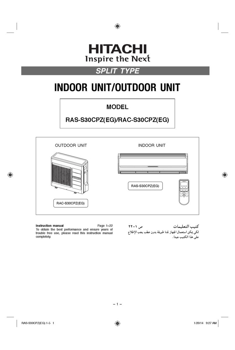
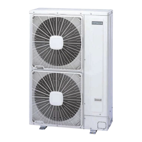
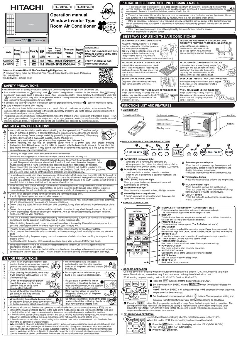
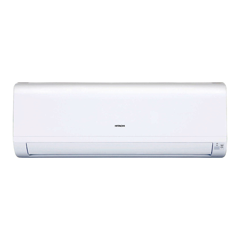
  9. Hitachi RAK-15QEF User manual

Hitachi RAK-15QEF User manual

Other manuals for RAK-15QEF

1

This manual suits for next models

7

Other Hitachi Air Conditioner manuals

Hitachi RAS-S18CPA User manual

Hitachi

Hitachi RAS-S18CPA User manual

Hitachi RAS-S10H2 User manual

Hitachi

Hitachi RAS-S10H2 User manual

Hitachi RAK-25NH5 User manual

Hitachi

Hitachi RAK-25NH5 User manual

Hitachi RAM-90NP5A User manual

Hitachi

Hitachi RAM-90NP5A User manual

Hitachi RAS-51CHA3 User manual

Hitachi

Hitachi RAS-51CHA3 User manual

Hitachi RA-06SR User manual

Hitachi

Hitachi RA-06SR User manual

Hitachi RAK-50PPA User manual

Hitachi

Hitachi RAK-50PPA User manual

Hitachi RUA-NP20ATS User manual

Hitachi

Hitachi RUA-NP20ATS User manual

Hitachi 4FSVN1Q Instruction Manual

Hitachi

Hitachi 4FSVN1Q Instruction Manual

Hitachi airHome RAD-DJ18QHAE User manual

Hitachi

Hitachi airHome RAD-DJ18QHAE User manual

Hitachi RAF-35RXB User manual

Hitachi

Hitachi RAF-35RXB User manual

Hitachi RAS-18C9 User manual

Hitachi

Hitachi RAS-18C9 User manual

Hitachi air365 Max Series Instruction Manual

Hitachi

Hitachi air365 Max Series Instruction Manual

Hitachi RAS-60YHA2 User manual

Hitachi

Hitachi RAS-60YHA2 User manual

Hitachi RAS-S10CYK User manual

Hitachi

Hitachi RAS-S10CYK User manual

Hitachi RAS-X10HAK User manual

Hitachi

Hitachi RAS-X10HAK User manual

Hitachi RAK-18QXB User manual

Hitachi

Hitachi RAK-18QXB User manual

Hitachi RAS-F10CF User manual

Hitachi

Hitachi RAS-F10CF User manual

Hitachi RAS-25CNH2 User manual

Hitachi

Hitachi RAS-25CNH2 User manual

Hitachi RAS-18GH5 User manual

Hitachi

Hitachi RAS-18GH5 User manual

Hitachi 0584E User manual

Hitachi

Hitachi 0584E User manual

Hitachi RAS-50YHA4 User manual

Hitachi

Hitachi RAS-50YHA4 User manual

Hitachi RAC-112SQB User manual

Hitachi

Hitachi RAC-112SQB User manual

Hitachi RAS-S28H2A User manual

Hitachi

Hitachi RAS-S28H2A User manual

Popular Air Conditioner manuals by other brands

Fujitsu ASYG 09 LLCA installation manual

Fujitsu

Fujitsu ASYG 09 LLCA installation manual

York HVHC 07-12DS Installation & owner's manual

York

York HVHC 07-12DS Installation & owner's manual

Carrier Fan Coil 42B Installation, operation and maintenance manual

Carrier

Carrier Fan Coil 42B Installation, operation and maintenance manual

intensity IDUFCI60KC-3 installation manual

intensity

intensity IDUFCI60KC-3 installation manual

Frigidaire FAC064K7A2 Factory parts catalog

Frigidaire

Frigidaire FAC064K7A2 Factory parts catalog

Sanyo KS2432 instruction manual

Sanyo

Sanyo KS2432 instruction manual

LG MultiV Series installation manual

LG

LG MultiV Series installation manual

CLIMAVENETA a-CHD U-2T 606+2209 OPERATING AND INSTALLATION Manual

CLIMAVENETA

CLIMAVENETA a-CHD U-2T 606+2209 OPERATING AND INSTALLATION Manual

Midea EWK06CW5 user manual

Midea

Midea EWK06CW5 user manual

Pioneer FAB Series installation manual

Pioneer

Pioneer FAB Series installation manual

SPT WA-1511S user manual

SPT

SPT WA-1511S user manual

Mitsubishi Electric Mr.Slim MSZ-A24NA operating instructions

Mitsubishi Electric

Mitsubishi Electric Mr.Slim MSZ-A24NA operating instructions

Mitsubishi Electric PUHZ-RP50VHA4 Service manual

Mitsubishi Electric

Mitsubishi Electric PUHZ-RP50VHA4 Service manual

Panasonic CS-S18HKQ Service manual

Panasonic

Panasonic CS-S18HKQ Service manual

Panasonic CS-E15NKE3 operating instructions

Panasonic

Panasonic CS-E15NKE3 operating instructions

Gree GWH18TC-K3DNA1B/I Service manual

Gree

Gree GWH18TC-K3DNA1B/I Service manual

Friedrich ZoneAire Compact P08SA owner's manual

Friedrich

Friedrich ZoneAire Compact P08SA owner's manual

Daikin R32 Split Series installation manual

Daikin

Daikin R32 Split Series installation manual

manuals.online logo
manuals.online logoBrands
  • About & Mission
  • Contact us
  • Privacy Policy
  • Terms and Conditions

Copyright 2025 Manuals.Online. All Rights Reserved.

SPECIFICATIONS AND PARTS ARE SUBJECT TO CHANGE FOR IMPROVEMENT
ROOM AIR CONDITIONER
INDOOR UNIT
SERVICE MANUAL
REFER TO THE FOUNDATION MANUAL
TECHNICAL INFORMATION
FOR SERVICE PERSONNEL ONLY
CONTENTS
SPECIFICATIONS ----------------------------------------------------------------
HOW TO USE ----------------------------------------------------------------------
CONSTRUCTION AND DIMENSIONAL DIAGRAM ---------------------
MAIN PARTS COMPONENT --------------------------------------------------
WIRING DIAGRAM ---------------------------------------------------------------
CIRCUIT DIAGRAM --------------------------------------------------------------
BLOCK DIAGRAM ----------------------------------------------------------------
BASIC MODE ----------------------------------------------------------------------
REFRIGERATING CYCLE DIAGRAM --------------------------------------
DESCRIPTION OF MAIN CIRCUIT OPERATION ------------------------
SERVICE CALL Q & A ----------------------------------------------------------
PROCEDURE FOR DISASSEMBLY AND REASSEMBLY -----------
PARTS LIST AND DIAGRAM --------------------------------------------------
RAR-7PE1
INDOOR UNIT
RAC-18WEF,RAC-25WEF,RAC-35WEF,RAC-50WEF(JCH-WH NO.0132E)
for items not described in this manual.
Johnson Controls-Hitachi Air Conditioning Wuhu Co., Ltd.
SPECIFICATIONS
RAK-15QEF
RAK-18REF
RAK-25REF
RAK-50REF
RAK-25REFC
RAK-35REFC
RAK-35REF RAK-50REFC
RAK-15QEF
RAK-18REF
RAK-25REF
RAK-50REF
RAK-25REFC
RAK-35REFC
RAK-35REF RAK-50REFC
80
40
54
42
38
25
24
23
21
20
19
8
6
NO.0131EJCH-WH
INDOOR UNIT OUTDOOR UNIT INDOOR UNIT OUTDOOR UNIT INDOOR UNIT OUTDOOR UNIT INDOOR UNIT OUTDOOR UNIT
RAK-18REF RAC-18WEF RAK-25REF
RAK-25REFC RAC-25WEF RAC-35WEF
RAK-35REF
RAK-35REFC
RAK-50REF
RAK-50REFC RAC-50WEF
(KW)
(B.T.U./h)
(KW)
(B.T.U./h)
W 780 660(+60) 780 660(+60) 780 660(+60) 780 792(+91)
H 280 530 280 530 280 530 280 600
D 215 278(+55) 215 278(+55) 215 278(+55) 215 299(+47)
MODEL
POWER SOURCE
TOTAL INPUT (W
TOTAL AMPERES (A)
CAPACITY
COOLING
HEATING
TOTAL INPUT (W
TOTAL AMPERES (A)
CAPACITY
1,090 (250 1,460)
DIMENSIONS
(mm)
1,560 (500 2,100)
3.19-3.05
2.00 (0.90 2.50)
6,820 (3,070 8,530)
620 (250 970)
2.50 (0.90 3.20)
3.62-3.46
7.7 23.7 7.7 23.7 7.7 25.0 39.5
8,530 (3,070 10,920)
880 (250 1,250)
NET WEIGHT (Kg)
TYPE DC INVERTER
V032-022,zH05,ESAHP1 V032-022,zH05,ESAHP1 V032-022,zH05,ESAHP1 V032-022,zH05,ESAHP1
580 ( 700 (250 1,290)1,010)
4.56-4.36
3.40 (0.90 4.40)
11,600 (3,070 15,010)
5.41-5.18
1,100 (250 1,700)
5.56-5.31
14,330 (3,070 17,060)
3.84-3.67
2.50 (0.90 3.10)
8,530 (3,070 10,580)
7.16-6.85
3.50 (0.90 4.00) 5.00 (1.90 5.20)
11,940 (3,070 13,650) 17,060 (6,480 17,740)
20,470 (7,510 24,910)
7.62-7.29
1,660 (500 2,750)
4.20 (0.90 5.00) 6.00 (2.20 7.30)
250
8.2
1
 



 


! "

# $

% 

& '

( 
)
* '

' %++,-.
/ '



+ ")

 .







 





!
#
%
DANGER
2
WORKING STANDARDS FOR PREVENTING BREAKAGE OF SEMICONDUCTORS
1. Scope
The standards provide for items to be generally observed in carrying and handling semiconductors in
relative manufactures during maintenance and handling thereof. (They apply the same to handling of
abnormal goods such as rejected goods being returned.)
2. Object parts
(1) Microcomputer
(2) Integrated circuits (I.C.)
(3) Field effective transistor (F.E.T.)
(4) P.C. boards or the like to which the parts mentioned in (1) and (2) of this paragraph are equipped.
3. Items to be observed in handling
(1) Use a conductive container for carrying and storing of parts. (Even rejected goods should be handled in
the same way.)
(2) When any part is handled uncovered (in counting, packing and the like), the handling person must
always use himself as a body earth. (Make yourself a body earth by passing one M ohm earth
resistance through a ring or bracelet.)
(3) Be careful not to touch the parts with your clothing when you hold a part even if a body earth is
being taken.
(4) Be sure to place a part on a metal plate with grounding.
(5) Be careful not to fail to turn off power when you repair the printed circuit board. At the same time,
try to repair the printed circuit board on a grounded metal plate.
HITACH I IC401TH 1 ,188UV
Fig. 1 Conductive container
A conductive polyvinyl bag
IC
IC
Conductive sponge
Fig. 2 Body earth
Body earth (Elimik conductive band)
Clip for connection with
a grounding wire
1MΩ
3
(6) Use a three wire type soldering iron including a grounding wire.
Fig.4 Grounding a solder iron
Use a high insulation mode (100V, 10MΩor higher) when ordinary iron is to be used.
(7) In checking circuits for maintenance, inspection, or some others, be careful not to have the test probes
of the measuring instrument short circuit a load circuit or the like.
Bare copper wire (for body earth)
Metal plate (of Al. stainless steel, etc.)
Working table
Resistor 1MΩ(1/2W)
Earth wire
Staple
Fig.3 Grounding of the working table
soldering iron
Grounding wire
Screw stop at the screwed
part using a rag plate
4
1.
In quiet or stop operation, slight flowing noise of refrigerant in the refrigerating cycle is heard occasionally,
but this noise is not abnormal for the operation.
2. When it thunders near by, it is recommend to stop the operation and turn off the circuit break er for safety.
3. In the event of power failure,the room air conditioner will restare automatically in the previously
mode once the power is restored. In the event of power failure during TIMER operation, the room air comditioner
will not start automatically. Re-press ON/OFF button after 3 minutes from when the unit off or power recovery.
4. If the room air conditioner is stopped by adjusting thermostat, or missoperation, and re-start in a moment,
there is occasion that the cooling and heating operation does not start for 3 minutes, it is not abnormal and
this is the result of the operation of IC delay circuit. This IC delay circuit ensures that there is no danger of
blowing fuse or damaging parts even if operation is restarted accidentally.
5. This room air conditioner should not be used at the cooling operation when the outside temperature is
below -10°C (14°F).
6. This room air conditioner (the reverse cycle) should not be used when the outside temperature is below
–15°C (5°F).
If the reverse cycle is used under this condition, the outside heat exchanger is frosted and efficiency falls.
7. When the outside heat exchanger is frosted, the frost is melted by operating the hot gas system, it is not
trouble that at this time fan stops and the vapour may rise from the outside heat exchanger.
!
CAUTION
selected
5
SPECIFICATIONS
38W (DC340 V)
RAK-15QEF,RAK-18REF,RAK-25REF,RAK-35REF
RAK-50REF,RAK-25REFC,RAK-35REFC,RAK-50REFC
6
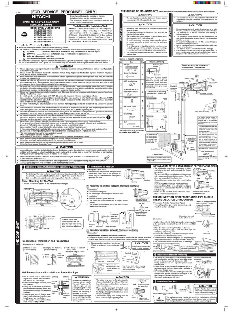
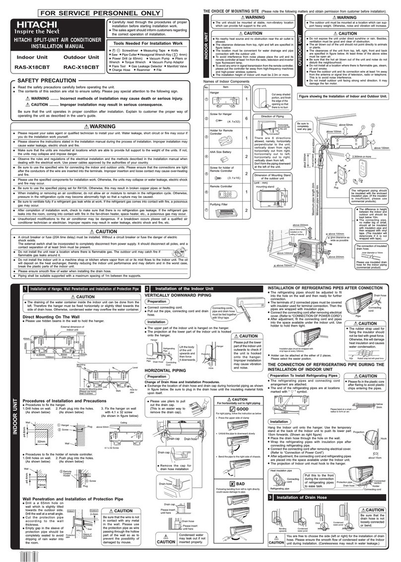
Figure showing the installation of lndoor unit
MODEL RAK-15QEF
RAK-18/25/35/50REF
RAK-25/35/50REFC
above
50mm
above
50mm
above 50mm
about 300mm
about 450mm
must not bend
The indoor piping
should be insulated
with the enclosed
insulation pipe. (If the
insulator is insufficient,
please use commercial
products.)
2300 mm or more
Be sure to
completely
seal any
gap with
putty.
7
Remote Controller Manual
Remote Controller manual
Page 1~12
To obtain the best performance and ensure years of trouble free use, please read this instruction manual completely.
MODEL
RAR-7PE1
-1-
<0016692Y>
NAMES AND FUNCTIONS OF REMOTE CONTROLLER
This controls the operation function and timer setting of the room air conditioner. The range of control
is about 7 meters. lf indoor lighting is controlled electronically, the range of control may be shorter.
Precautions for Use
• Do not put the remote controller under direct sunlight and high temperature.
• Do not drop it on the floor, and protect it from water.
• If you press the FUNCTION button during operation, the air conditioner may stop for about 3 minutes
for protection before you can start it again.
Signal Transmission
MODE selector Button
Use this button to select the
operating mode. Every time
you press this button, the
mode will change from
(AUTO) (HEAT)
(DEHUMIDIFY)
(COOL) and (FAN)
cyclically.
(
Page 3)
ECO Button
Use this button to set the
ECO mode.
(
Page

)
TIMER OFF Button
Select the turn OFF time.
(
Page

)
TIMER ON Button
Select the turn ON time.
(
Page

)
POWERFUL Button
Press this button to start
powerful operation.
(
(
Page

)
Transmission Sign
Th
e
tra
ns
missio
n
sign blinks
when
a signal
has
bee
n
send.
ON/OFF Button
Press this button to start
operation.
Press it again to stop operation.
( Page
( Page

)
TEMPERATURE Button
Room temperature setting.
Value will change quic
k
er when
keep pressing.
(
Page 3)
FAN SPEED Button
Select the
f
an speed
f
or
cooling
and heating mode.
(
Page

)
UP/DOWN Button
Control the angle of the
horizontal air deflector.
(
(
Page

)
LEAVE HOME Button
(
Page

)
FROST WASH/CLEAN
Button
(
Page

)
-2-
8
AUTOMATIC OPERATION
The device will automatically determine the mode of operation, HEAT or COOL depending on the current room
temperature. The selected mode of operation will change when the room temperature varies.
However, the mode of operation will not change when indoor unit is connected to multi type outdoor unit.
VARIOUS FUNCTIONS
■Auto Restart Control
●
If there is a power failure, operation will be automatically restarted when the power is resumed with previous
operation mode and airflow direction.
(As the operation is not stopped by remote controller.)
●
If you intend not to continue the operation when the power is resumed, switch off the power supply.
When you switch on the circuit breaker, the operation will be automatically restarted with previous operation
mode and airflow direction.
Note: 1. If you do not require Auto Restart Control, please consult your sales agent.
2. Auto Restart Control is not available when Timer or Sleep Timer mode is set.
■
As the settings are stored in the memory of the remote controller,
you only have to press the
(ON/OFF) button next time.
Press the MODE selector button so that the display indicates
the (AUTO) mode of operation.
●
When AUTO has been selected,
t
he
de
vice
will
a
ut
o
ma
tic
al
ly
determine the mod
e
of ope
ra
tio
n,
HEAT
o
HEAT
HEAT
r COOL
d
e
pe
n
di
ng
on
the c
ur
r
ent r
oom
t
em
pe
ra
tu
r
e. H
owever
th
e m
od
e of
operation will not change when indoor unit is connected to
multi type outdoor unit.
●
If the mode automatically selected by the unit is not
satisfactory, manually change the mode setting (HEAT,
DEHUMIDIFY, COOL or FAN).
Press the (FAN SPEED) button to select AUTO, HIGH, MED,
LOW or SILENT.
Press the
(ON/OFF) button.
Operation starts with a beep.
Press the button again to stop operation.
Set the desired room temperature with the TEMPERATURE
buttons (the display indicates the setting).
The temperature setting and the actual room temperature may
vary depending on conditions.
1
2
3
Set the desired FAN SPEED with the (FAN SPEED) button
(the display indicates the setting).
(AUTO)
(HIGH)
(MED)
(SILENT)
(LOW)
(AUTO)
(HIGH)
START
STOP
Temperature range can be set between 16°C and 32°C.
-3-
HEATING OPERATION
●
Use the device for heating when the outdoor temperature is under 21°C.
When it is too warm (over 21°C), the heating function may not work in order to protect the device.
●
In order to keep reliability of the device, please use this device above –15°C of the outdoor
temperature.
Defrosting will be performed about once an hour when frost forms on the heat exchange of the
outdoor unit, for 5~10 minutes each time.
During defrosting operation, the operation lamp blinks in cycle of 2 seconds on and 1 second off.
The maximum time for defrosting is 20 minutes.
However, if the indoor unit is connected to multi type outdoor unit, the maximum time for defrosting
is 15 minutes.
(If the piping length used is longer than usual, frost will likely to form.)
Defrosting
■
Press the MODE selector button so that the display indicates
(HEAT).
Set the desired FAN SPEED with the (FAN SPEED) button
(the display indicates the setting).
(AUTO)
(HIGH)
(MED)
(SILENT)
(LOW)
Set the desired room temperature with the TEMPERATURE buttons
(the display indicates the setting).
The temperature setting and the actual room temperature may
vary depending on conditions.
Temperature range can be set between 16°C and 32°C.
Press the
(ON/OFF) button. Heating operation starts with
a beep. Press the button again to stop operation.
■
As the settings are stored in the memory of the remote controller, you
only have to press the
(ON/OFF) button next time.
■
During AUTO fan, the fan speed automatically changes as below:
●
When the difference between room temperature and setting temperature
is large, fan starts to run at HI speed.
●
After room temperature reaches the preset temperature, fan speed
will be changed to lower speed to obtain optimum room temperature
condition for natural healthy heating.
1
2
3
(AUTO)
(HIGH)
START
STOP
-4-
9
DEHUMIDIFYING OPERATION
■Dehumidifying Function
Use the device for dehumidifying when the room temperature is over 16°C.
When it is under 15°C, the dehumidifying function will not work.
●
When the room temperature is higher than the temperature setting: The device will dehumidify the room,
reducing the room temperature to the preset level.
When the room temperature is lower than the temperature setting: Dehumidifying will be performed at the
temperature setting slightly lower than the current room temperature, regardless of the temperature setting.
●
The preset room temperature may not be reached depending on the number of people present in the room
or other room conditions.
Set the desired room temperature with the ROOM
TEMPERATURE setting buttons (the display indicates the
setting).
The range of 20˚C to 26˚C is recommended as
the room temperature for dehumidifying.
Temperature range can be set between 16°C and
32°C.
Press the
(ON/OFF) button. Dehumidifying operation
starts with a beep. Press the button again to stop operation.
■
As the settings are stored in the memory of the remote controller, you
only have to press the
(ON/OFF) button next time.
STA
RT
STO
P
Press the MODE selector button so that the display
indicates
(DEHUMIDIFY).
The fan speed is set at LOW.
Press (FAN SPEED) button to select SILENT or LOW fan
speed.
1
2
-5-
COOLING OPERATION
Use the device for cooling when the outdoor temperature is -10 to 46°C.
If humidity is very high (over 80%) indoors, some dew may form on the air outlet grille of the indoor unit.
Press the MODE selector button so that the display indicates
(COOL).
■
As the settings are stored in memory in the remote controller, you only
have to press the
(ON/OFF) button next time.
1
2
3
Set the desired FAN SPEED with the (FAN SPEED) button (the
display indicates the setting).
Set the desired room temperature with the TEMPERATURE buttons
(the display indicates the setting).
The temperature setting and the actual room temperature may vary
d
e
p
e
n
d
i
n
g
o
n
c
o
n
d
i
t
i
o
n
s
.
Press the
(ON/OFF) button. Cooling operation starts with a
beep. Press the button again to stop operation. The cooling function
does not start if the temperature setting is higher than the current
room temperature (even though the
(OPERATION) lamp lights).
The cooling function will start as soon as you set the temperature
below the current room temperature.
STA
RT
STO
P
■
During AUTO fan, the fan speed automatically changes as below:
●
When the difference between room temperature and setting tem-
perature is large, fan starts to run at HI speed.
●
After room temperature reaches the preset temperature, fan speed
will be changed to lower speed to obtain optimum room temperature
condition for natural healthy cooling.
(AUTO)
(HIGH)
(MED)
(SILENT)
(LOW)
(AUTO)
(HIGH)
Temperature range can be set between 16°C and 32°C.
-6-
10