manuals.online logo
Brands
  1. Home
  2. •
  3. Brands
  4. •
  5. Hitachi
  6. •
  7. Air Conditioner
  8. •
  9. Hitachi RAS-10JH3 User manual

Hitachi RAS-10JH3 User manual

This manual suits for next models

3

Other Hitachi Air Conditioner manuals

Hitachi RAC-S18H2 User manual

Hitachi

Hitachi RAC-S18H2 User manual

Hitachi RAS-25CNH2 User manual

Hitachi

Hitachi RAS-25CNH2 User manual

Hitachi airCore 700 Instruction Manual

Hitachi

Hitachi airCore 700 Instruction Manual

Hitachi RA-08HV User manual

Hitachi

Hitachi RA-08HV User manual

Hitachi YUTAKI Series User manual

Hitachi

Hitachi YUTAKI Series User manual

Hitachi FSG Series User manual

Hitachi

Hitachi FSG Series User manual

Hitachi RAK-18PPB User manual

Hitachi

Hitachi RAK-18PPB User manual

Hitachi RAC-90JP User manual

Hitachi

Hitachi RAC-90JP User manual

Hitachi MULTIZONE RAM-40NE2F User manual

Hitachi

Hitachi MULTIZONE RAM-40NE2F User manual

Hitachi RAK-18NH6A User manual

Hitachi

Hitachi RAK-18NH6A User manual

Hitachi RAC-25NXA1 User manual

Hitachi

Hitachi RAC-25NXA1 User manual

Hitachi RAC-18WED User manual

Hitachi

Hitachi RAC-18WED User manual

Hitachi RAC-18WEB User manual

Hitachi

Hitachi RAC-18WEB User manual

Hitachi E Series User manual

Hitachi

Hitachi E Series User manual

Hitachi airHome 800 User manual

Hitachi

Hitachi airHome 800 User manual

Hitachi RPI-0.8FSNQL(H) Instruction Manual

Hitachi

Hitachi RPI-0.8FSNQL(H) Instruction Manual

Hitachi DXF-2.0A1 Instruction Manual

Hitachi

Hitachi DXF-2.0A1 Instruction Manual

Hitachi RAS-18GH4 User manual

Hitachi

Hitachi RAS-18GH4 User manual

Hitachi RAD-70PPD User manual

Hitachi

Hitachi RAD-70PPD User manual

Hitachi UTOPIARAS-(2/2.5)HVNP1 User manual

Hitachi

Hitachi UTOPIARAS-(2/2.5)HVNP1 User manual

Hitachi RAC-14KH2 User manual

Hitachi

Hitachi RAC-14KH2 User manual

Hitachi RAC-07CH5 User manual

Hitachi

Hitachi RAC-07CH5 User manual

Hitachi RAS-AJ18CMT User manual

Hitachi

Hitachi RAS-AJ18CMT User manual

Hitachi RCI-1.0FSN3 Instruction Manual

Hitachi

Hitachi RCI-1.0FSN3 Instruction Manual

Popular Air Conditioner manuals by other brands

Fujitsu ASYG 09 LLCA installation manual

Fujitsu

Fujitsu ASYG 09 LLCA installation manual

York HVHC 07-12DS Installation & owner's manual

York

York HVHC 07-12DS Installation & owner's manual

Carrier Fan Coil 42B Installation, operation and maintenance manual

Carrier

Carrier Fan Coil 42B Installation, operation and maintenance manual

intensity IDUFCI60KC-3 installation manual

intensity

intensity IDUFCI60KC-3 installation manual

Frigidaire FAC064K7A2 Factory parts catalog

Frigidaire

Frigidaire FAC064K7A2 Factory parts catalog

Sanyo KS2432 instruction manual

Sanyo

Sanyo KS2432 instruction manual

LG MultiV Series installation manual

LG

LG MultiV Series installation manual

CLIMAVENETA a-CHD U-2T 606+2209 OPERATING AND INSTALLATION Manual

CLIMAVENETA

CLIMAVENETA a-CHD U-2T 606+2209 OPERATING AND INSTALLATION Manual

Midea EWK06CW5 user manual

Midea

Midea EWK06CW5 user manual

Pioneer FAB Series installation manual

Pioneer

Pioneer FAB Series installation manual

SPT WA-1511S user manual

SPT

SPT WA-1511S user manual

Mitsubishi Electric Mr.Slim MSZ-A24NA operating instructions

Mitsubishi Electric

Mitsubishi Electric Mr.Slim MSZ-A24NA operating instructions

Mitsubishi Electric PUHZ-RP50VHA4 Service manual

Mitsubishi Electric

Mitsubishi Electric PUHZ-RP50VHA4 Service manual

Panasonic CS-S18HKQ Service manual

Panasonic

Panasonic CS-S18HKQ Service manual

Panasonic CS-E15NKE3 operating instructions

Panasonic

Panasonic CS-E15NKE3 operating instructions

Gree GWH18TC-K3DNA1B/I Service manual

Gree

Gree GWH18TC-K3DNA1B/I Service manual

Friedrich ZoneAire Compact P08SA owner's manual

Friedrich

Friedrich ZoneAire Compact P08SA owner's manual

Daikin R32 Split Series installation manual

Daikin

Daikin R32 Split Series installation manual

manuals.online logo
manuals.online logoBrands
  • About & Mission
  • Contact us
  • Privacy Policy
  • Terms and Conditions

Copyright 2025 Manuals.Online. All Rights Reserved.

AW NO. 0031E
SERVICE MANUAL
TECHNICAL INFORMATION
REFER TO THE FOUNDATION MANUAL
ROOM AIR CONDITIONER
INDOOR UNIT + OUTDOOR UNIT
SPECIFICATIONS AND PARTS ARE SUBJECT TO CHANGE FOR IMPROVEMENT
FOR SERVICE PERSONNEL ONLY
SPECIFICATIONS
SPECIFICATIONS ‥‥‥‥‥‥‥‥‥‥‥‥‥‥‥
HOW TO USE ‥‥‥‥‥‥‥‥‥‥‥‥‥‥‥‥
CONSTRUCTION AND DIMENSIONAL DIAGRAM
‥‥
MAIN PARTS COMPONENT ‥‥‥‥‥‥‥‥‥‥
WIRING DIAGRAM ‥‥‥‥‥‥‥‥‥‥‥‥‥‥
BLOCK DIAGRAM‥‥‥‥‥‥‥‥‥‥‥‥‥‥‥
BASIC MODE‥‥‥‥‥‥‥‥‥‥‥‥‥‥‥‥‥
REFRIGERATING CYCLE DIAGRAM ‥‥‥‥‥‥
DESCRIPTION OF MAIN CIRCUIT OPERATION
‥‥‥
SERVICE CALL Q & A ‥‥‥‥‥‥‥‥‥‥‥‥
TROUBLE SHOOTING ‥‥‥‥‥‥‥‥‥‥‥‥
PROCEDURE FOR DISASSEMBLY AND REASSEMBLY
‥‥
PARTS LIST AND DIAGRAM ‥‥‥‥‥‥‥‥‥
CONTENTS
4
5
22
24
26
29
30
37
38
68
72
102
105
INDOOR UNIT
RAS-10JH3
RAS-14JH3
OUTDOOR UNIT
RAC-10JH3
RAC-14JH3
RAS-10JH3 / RAC-10JH3
RAS-14JH3 / RAC-14JH3
(W)
(A)
(kW)
(B.T.U./h)
(W)
(A)
(kW)
(B.T.U./h)
W
H
D
(kg)
RAS-10JH3 RAC-10JH3
DC INVERTER (WALL TYPE)
TYPE
MODEL
POWER SOURCE
TOTAL INPUT
TOTAL AMPERES
CAPACITY
TOTAL INPUT
TOTAL AMPERES
CAPACITY
DIMENSIONS
(mm)
NET WEIGHT
790
298
210
10
COOLING
HEATING
INDOOR UNIT OUTDOOR UNIT
1 PHASE, 50Hz, 220-230V
580 (155 - 1,160)
3.11 - 2.97
2.50 (0.90 - 3.10)
8,530 (3,070 - 10,580)
795 (115 - 1,170)
4.02 - 3.85
3.40 (0.90 - 4.40)
11,600 (3,070 - 15,010)
750(+91)※
(+47)※
548
288
35
RAS-14JH3 RAC-14JH3
790
298
210
10
INDOOR UNIT OUTDOOR UNIT
1 PHASE, 50Hz, 220-230V
990 (155 - 1,380)
4.74 - 4.54
3.50 (0.90 - 4.00)
11,940 (3,070 - 13,650)
1,040 (115 - 1,350)
4.98 - 4.76
4.20 (0.90 - 5.00)
14,330 (3,070 - 17,060)
750(+91)※
(+47)※
548
288
35
After installation
※
APRIL
2009
Hitachi Household Appliances (Wuhu) Co., Ltd.
1. In order to disassemble and repair the
unit in question, be sure to disconnect the
power cord plug from the power outlet
before starting the work.
2. If it is necessary to replace any parts, they should be replaced with respective genuine parts for the unit,
and the replacement must be effected in correct manner according to the instructions in the Service
Manual of the unit.
3. After completion of repairs, the initial state should be
restored.
4. Lead wires should be connected and laid as in the
initial state.
5. Modification of the unit by the user himself should
absolutely be prohibited.
6. Tools and measuring instruments for use in repairs or inspection should be accurately calibrated in
advance.
7. In installing the unit having been repaired, be careful to prevent the occurrence of any accident such as
electrical shock, leak of current, or bodily injury due to the drop of any part.
8. To check the insulation of the unit, measure the insulation resistance between the power cord plug and
grounding terminal of the unit.
The insulation resistance should be 1M or more as measured by a 500V DC megger.
9. The initial location of installation such as window, floor or the other should be checked for being safe
enough to support the repaired unit again.
If it is found not so strong and safe, the unit should be installed at the initial location after reinforced or
at a new location.
10. Any inflammable object must not be placed
about the location of installation.
11. Check the grounding to see whether it is
proper or not, and if it is found improper,
connect the grounding terminal to the earth.
Spray
gasoline
gasbombe
thinner
SAFETY DURING REPAIR WORK
If the contacts of electrical
parts are defective, replace
the electrical parts without
trying to repair them
1
2
3
4
5
DANGER
WORKING STANDARDS FOR PREVENTING BREAKAGE OF SEMICONDUCTORS
1. Scope
The standards provide for items to be generally observed in carrying and handling semiconductors in
relative manufactures during maintenance and handling thereof. (They apply the same to handling of
abnormal goods such as rejected goods being returned.)
2. Object parts
(1) Micro computer
(2) Integrated circuits (I.C.)
(3) Field effective transistor (F.E.T.)
(4) P.C. boards or the like to which the parts mentioned in (1) and (2) of this paragraph are equipped.
3. Items to be observed in handling
(1) Use a conductive container for carrying and storing of parts. (Even rejected goods should be handled in
the same way.)
(2) When any part is handled uncovered (in counting, packing and the like), the handling person must
always use himself as a body earth. (Make yourself a body earth by passing one M ohm earth
resistance through a ring or bracelet.)
(3) Be careful not to touch the parts with your clothing when you hold a part even if a body earth is
being taken.
(4) Be sure to place a part on a metal plate with grounding.
(5) Be careful not to fail to turn off power when you repair the printed circuit board. At the same time,
try to repair the printed circuit board on a grounded metal plate.
HITACHI IC401TH1,188UV
Fig. 1 Conductive container
A conductive polyvinyl bag
IC
IC
Conductive sponge
Fig. 2 Body earth
Body earth (Elimik conductive band)
Clip for connection with
a grounding wire
1MΩ
- 1 -
(6) Use a three wire type soldering iron including a grounding wire.
Fig.4 Grounding a solder iron
Use a high insulation mode (100V, 10M Ωor higher) when ordinary iron is to be used.
(7) In checking circuits for maintenance, inspection, or some others, be careful not to have the test probes
of the measuring instrument shortcircuit a load circuit or the like.
Bare copper wire (for body earth)
Metal plate (of Al. stainless steel, etc.)
Working table
Resistor 1MΩ(1/2W)
Earth wirte
Staple
Fig.3 Grounding of the working table
soldering iron
Grounding wire
Screw stop at the screwed
part using a rag plate
- 2 -
1. In quiet operation or stopping the running, slight flowing noise of refrigerant in the refrigerating cycle is
heard occasionally, but this noise is not abnormal for the operation.
2. When it thunders near by, it is recommend to stop the operation and to disconnect the power cord plug from
the power outlet for safety.
3. The room air conditioner does not start automatically after recovery of the electric power failure for prevent-
ing fuse blowing. Re-press START/STOP button after 3 minutes from when unit stopped.
4. If the room air conditioner is stopped by adjusting thermostat, or missoperation, and re-start in a moment,
there is occasion that the cooling and heating operation does not start for 3 minutes, it is not abnormal and
this is the result of the operation of IC delay circuit. This IC delay circuit ensures that there is no danger of
blowing fuse or damaging parts even if operation is restarted accidentally.
5. This room air conditioner should not be used at the cooling operation when the outside temperature is
below−10℃(14°F).
6. This room air conditioner (the reverse cycle) should not be used when the outside temperature is below
−15℃(5°F).
If the reverse cycle is used under this condition, the outside heat exchanger is frosted and efficiency falls.
7. When the outside heat exchanger is frosted, the frost is melted by operating the hot gas system, it is not
trouble that at this time fan stops and the vapour may rise from the outside heat exchanger.

CAUTION
- 3 -
SPECIFICATIONS
MODEL
FAN MOTOR
FAN MOTOR CAPACITOR
FAN MOTOR PROTECTOR
COMPRESSOR
COMPRESSOR MOTOR CAPACITOR
OVERLOAD PROTECTOR
OVERHEAT PROTECTOR
FUSE (for MICROPROCESSOR)
POWER RELAY
POWER SWITCH
TEMPORARY SWITCH
SERVICE SWITCH
TRANSFORMER
VARISTOR
NOISE SUPPRESSOR
THERMOSTAT
REMOTE CONTROL SWITCH (LIQUID CRYSTAL)
40W (DC350V)
NO
NO
NO
EU1011E7
YES
YES
3.0A
G4A
NO
NO
YES
NO
450NR
YES
YES(IC)
NO
WITHOUT REFRIGERANT BECAUSE
COUPLING IS FLARE TYPE.
UNIT
PIPES (MAX. 20m)
REFRIGERANT CHARGING
VOLUME
(Refrigerant 410A)
870g
RAS-10JH3
RAS-14JH3
RAC-10JH3
RAC-14JH3
25W (DC35V)
NO
NO
—
NO
NO
NO
NO
NO
YES
NO
NO
NO
NO
YES(IC)
YES
----------
YES
- 4 -
– 4 –
·
Do not use any conductor as fuse wire, this could cause fatal accident.
·
During thunder storm, please stop operating the unit and turn off the circuit breaker.
·
Spray cans and other combustibles should not be located within a meter of the air outlets
of both indoor and outdoor units.
As a spray can’s internal pressure can be increased by hot air, a rupture may result.
·
The product shall be operated under the manufacturer specification and not for any
other intended use.
·
Do not attempt to operate the unit with wet hands. this could cause fatal accident.
·
When operating the unit with burning equipments, regularly ventilate the room
to avoid oxygen insufficiency.
·
Do not direct the cool air coming out from the air-conditioner panel to face household
heating apparatus as this may affect the working of apparatus such as the electric kettle,
oven etc.
·
Please ensure that outdoor mounting frame is always stable, firm and without defect. If
not, the outdoor unit may collapse and cause danger.
·
Do not wash the unit with water or place a water container such as a vase on the indoor
unit.
Electrical leakage could be present and cause electric.
·
Do not place plants or animals directly under the air flow as it is bad for the plants or
animals.
·
Do not climb on the outdoor unit or put objects on it.
·
When operating the unit with the door and windows opened, (the room humidity is always above
80%) and with the air deflector facing down or moving automatically for a long period
of time, water will condense on the air deflector and drips down occasionally. This will
wet your furniture. Therefore, do not operate under such condition for a long time.
·
If the amount of heat in the room is above the cooling or heating capability of the unit (for
example:more people entering the room, using heating equipments and etc.), the preset
room temperature cannot be achieved.
·
This appliance especially indoor unit cleaning must be performed by authorized
personnel only. Consult your sales agent.
Using a commercially available detergent or similar can damage the plastic parts or
clog the drain pipe, causing water to drip with potential electric shock hazard.
·
Do not touch the air outlet, bottom surface and aluminum fin of the outdoor
unit.
You may get hurt.
·
Do not touch the refrigerant pipe and connecting valve.
Burns may result.
·
This appliance is not intended for use by young children or infirm persons unless they have been
adequately supervised by a responsible person to ensure that they can use this appliance safely.
·
Young children should be supervised to ensure that they do not play with the appliance.
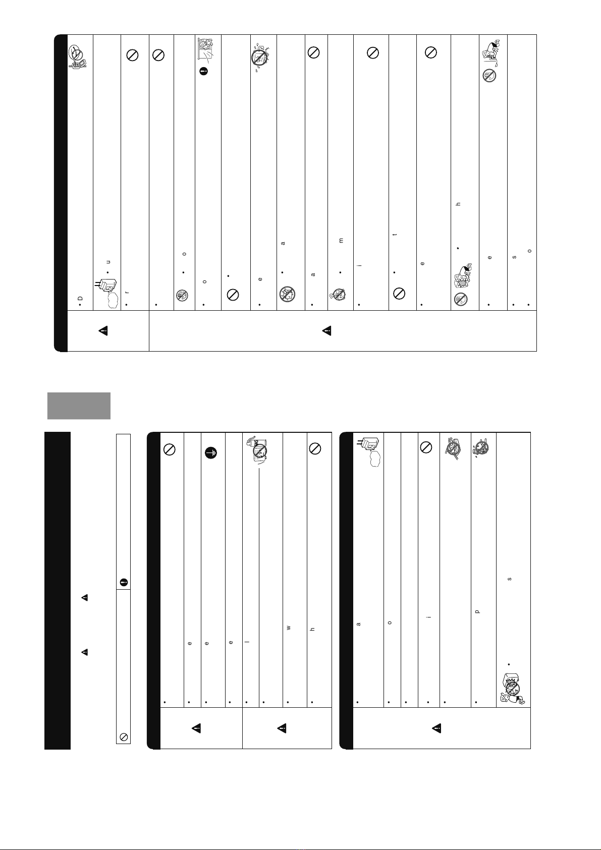
CAUTION
WARNING
PRECAUTIONS DURING OPERATION
"OFF"
DON'T WET
PROHIBITION
PROHIBITION
PROHIBITION
PROHIBITION
DON’T TOUCH
PROHIBITION
PROHIBITION
PROHIBITION
STRICTLY OBSERVE
PRECAUTIONS
PROHIBITION
PROHIBITION
PROHIBITION
PROHIBITION
DON’T TOUCH
HOW TO USE
– 3 –
ENGLISH
·
Do not reconstruct the unit.
Water leakage, fault, short circuit or fire may occur if you reconstruct the unit by
yourself.
·
Please ask your sales agent or qualified technician for the installation of your unit.
Water leakage, short circuit or fire may occur if you install the unit by yourself.
·
Please use earth line.
Do not place the earth line near water or gas pipes, lightning-conductor, or the earth
line of telephone. Improper installation of earth line may cause electric shock.
·
Be sure to use the specified piping set for R410A. Otherwise, this may result in broken
copper pipes or faults.
·
A circuit breaker should be installed depending on the mounting site of the unit. Without
a circuit breaker, the danger of electric shock exists.
·
Do not install the unit near location where there is flammable gas.
The outdoor unit may catch fire if flammable gas leaks around it. Piping shall be
suitable supported with a maximum spacing of 1m between the supports.
·
Please ensure smooth flow of water when installing the drain hose. If any failure is
found in the drain path, water drops from the indoor and outdoor units, causing wet
household effects.
·
Make sure that a single phase 230V power source is used.
The use of other power sources may cause electrical components to overheat and
lead to fire.
WARNING
WARNING
CAUTION
•
Please read the “Safety Precaution” carefully before operating the unit to ensure correct usage of the unit.
•
Pay special attention to signs of “ WARNING” and “ CAUTION”. The “Warning” section contains matters which, if
not observed strictly, may cause death or serious injury. The “Caution” section contains matters which may result in
serious consequences if not observed properly. Please observe all instructions strictly to ensure safety.
•
The signs indicate the following meanings. (The following are examples of signs.)
•
Please keep this manual after reading.
SAFETY PRECAUTION
PRECAUTIONS DURING INSTALLATION
PROHIBITION
PROHIBITION
·
Should abnormal situation arise (like burning smell), please stop operating the unit
and remove plug from the socket or turn off the circuit breaker. Contact your agent.
Fault, short circuit or fire may occur if you continue to operate the unit under abnormal
situation.
·
Please contact your agent for maintenance.
Improper self maintenance may cause electric shock and fire.
·
Please contact your agent if you need to remove and reinstall the unit.
Electric shock or fire may occur if you remove and reinstall the unit yourself improperly.
·
Avoid an extended period of direct air flow for your health.
·
Do not connect the power cable with an extension cable or do not plug too many leads
of the other electric appliance into the socket where this cable is plugged. In addition,
wire the cable with some allowances to prevent the cable from stretching. Not doing
so will cause an electrical shock, heat generation or fire.
·
Do not bundle the power cable, pull it, put something on it, heat it, process it, or put
it between things. Breakage of the power cable may result.
Use of a damaged cable may cause an electrical shock or a fire.
·
Do not put objects like thin rods into the panel of blower and suction side because the
high-speed fan inside may cause danger.
PRECAUTIONS DURING SHIFTING OR MAINTENANCE
"OFF"
PROHIBITION
CONNECT EARTH LINE
PROHIBITION
PROHIBITION
PROHIBITION
PROHIBITION
This sign in the figure indicates prohibition. Indicates the instructions that must be followed.
- 5 -
– 5 –
ENGLISH
Drain Hose
Drains the dehumidified water from the indoor unit to the
outdoor during “cooling” or “dehumidifying” operation.
Piping and Wiring
Air Inlets (Rear and left sides)
Air Outlet
When “heating” operation is performed,
cool air blows and when “cooling” or
“dehumidifying” operation is performed,
warm air blows.
Drain Port (Bottom)
Earth Terminal
(Lower section of the side)
Tw o Way Air Exchange Hose
This vents air from outside the room when the fresh air in is
operating. This vents air within the room to the outside when
the exhaust is operating.
Remote Controller
Send out operation signal to the indoor unit. So as to operate
the whole unit. (Refer page 8)
Fresh Air Window
This blows air from outside into the room while the fresh air in
is operating.
Tw o Way Air Exchange Fan (Internal)
This operates when the Tw o Way Air Exchange is operating.
Indoor Unit Indicators
Light
indicator showing the operating condition.(Refer page 7)
Signal Receiver
Receive the signal from the remote controller.
Horizontal deflector/Vertical deflector
(Air outlet)
(Refer page 24)
Air Purification Unit (Internal)
This traps cigarette smoke, pollen, etc.
(Refer page 10)
Pre-Filter (Internal)
To prevent dust from coming into the
indoor unit. (Refer page 27)
NAMES AND FUNCTIONS OF EACH PART
INDOOR UNIT
MODEL NAME AND DIMENSIONS
OUTDOOR UNIT
MODEL WIDTH (mm) HEIGHT (mm) DEPTH (mm)
RAS-10JH3, RAS-14JH3 790 298 210
RAC-10JH3, RAC-14JH3 750 548 288
About the outdoor unit:
•
When “Stop” is selected during operation of the
indoor unit, the fan of the outdoor unit continues
turning for 10 to 60 seconds to cool the electric
parts down.
•
In heating operation, condensate or water due
to defrosting will flow.
Do not cover the drain port of the outdoor unit
because such water may freeze in the chilly area.
•
When the outdoor unit is hung on the ceiling,
install the bush and drain pipe on the drain port
and drain water.
– 6 –
NAMES AND FUNCTIONS OF EACH PART
Exhaust Pre-Filter
This traps dirt and dust particles in
the air while the exhaust is
operating.
(Refer to page 25)
Nano-Titanium Disinfecting Deodorizing/
Dust Collecting Fresh Air In Filter
This deodorizes and eliminates dust from the air
ventilated from the outside.
(Refer to pages 11, 25)
Fresh Air In Pre-Filter
This traps dirt and dust particles in
the air ventilated from the outside.
(Refer to pages 11, 25)
Front Panel
Tw o Way Air Exchange Selection Switch
Select one of the following: “Prohibit Two Way Air Exchange”, “Only Exhaust”,
and “Operate Tw o Way Air Exchange”.
Please refer to page 33 regarding installation when the Two Way Air Exchange
cannot be operated.
(When the device is shipped out of the factory, it is set to “Operate Two Way Air
Exchange”.)
Operate after opening the front panel. (How to open the front panel, refer to page 10.)
Temporary Switch
If the remote controller does not work due
to battery failure, press this switch to start
and stop operation.
•This temporary operation will be at the
most recent setting mode. (The unit will
immediately go into automatic operation
once power is switched on.)
Power Switch
CAUTION
Tu rn off the circuit breaker or pull out
the power plug if the unit is not be
operated for a long period.
TWO WAY AIR EXCHANGE DUCT FILTER
If the power stays on and the unit is not operated, power is slightly consumed in the control circuit. The power is
saved by turning off the power switch (or the circuit breaker when the power is supplied from the outdoor unit).
INDOOR UNIT CONTROL PANEL
Dirt Sensor
The Dirt Sensor detects cigarette
smoke, sprays (pesticides), alcohol,
etc. (Refer to pages 19, 34)
- 6 -
– 7 –
ENGLISH
The “Two Way Air Exchange” lamp blinks in the following cases (It is not abnormal).
Configuring the Two Way Air Exchange Selection Switch to prohibited setting
•When “
Only Exhaust
” is selected and “
Fresh Air In During Sleep Mode Operation
” (page 23) is configured with the
remote controller to operate the
fresh air in
(page 18), the device beeps twice and the “Two Way Air Exchange” lamp
blinks (10 seconds).
•When “Prohibit Two Way Air Exchange” is selected and the “
Fresh Air In During Sleep Mode Operation
” (page 23) or the
“Automatic Tw o Way Air Exchange” (page 19) is configured with the remote controller to operate the
fresh air in
(page 18),
the device beeps twice and the “Two Way Air Exchange” lamp blinks (10 seconds).
While Operating the Two Way Air Exchange
•The two way air exchange is stopped during operation to prevent dew condensation on the two way air exchange fan
and hose and to protect the two way air exchange fan due to changes in the room temperature and outside air temperature.
At this time, the “Two Way Air Exchange” lamp blinks (lights for 10 seconds/out for 1 second) (page 32).
If the “Two Way Air Exchange” lamp blinks except for the above-mentioned case, the“TwoWay Air Exchange”
Fan is abnormal. (Refer page 32)
Self Clean Lamp (Yellow)
This lamp lights when the device
is configured to self clean.
(Refer page 19)
Tw o Way Air Exchange Lamp (Green)
This lamp lights when the fresh air in and
exhaust are operating.
Filter Lamp (Green)
When the device is operated for a total
of about 200 hours, the FILTER lamp
lights indicates that it is time to clean
the filter.The lamp goes out when the
“(AUTO SWING)” button is pressed
while the operation is stopped. But it
does not turn off when self clean is
working.
Operation Lamp (Yellow)
This lamp lights during operation.
The OPERATION LAMP blinks in the following cases during
heating.
(1) During Preheating
For about 2-3 minutes after starting up.
(2) During Defrosting
Defrosting will be performed about once an hour when frost
forms on the heat exchanger of the outdoor unit, for 5-10
minutes each time.
Timer Lamp (Orange)
This lamp lights when the timer is working.
INDOOR UNIT INDICATORS
– 8 –
NAMES AND FUNCTIONS OF EACH PART
Signal Emitting Window/Transmission Sign
Point this window toward the indoor unit when controlling it.
The transmission sign blinks when a signal is sent.
Display
This indicates the room temperature selected, current time, timer status,
function and intensity of circulation selected.
START / STOP Button
Press this button to start operation. Press it again to stop operation.
HEATING Button
Heating mode direct selection.
AU TO Button
Auto mode direct selection.
COOLING Button
Cooling mode direct selection.
TEMPERATURE Button
Use these buttons to raise or lower the temperature setting.
(Keep pressing and the value will change more quickly.)
FAN Button
This determines the fan speed. Every time you press these buttons, the
intensity of circulation will change from “ (AUTO) (HI)
(MED) (LOW) (SILENT)” (This button allows selecting the
optimal or preferred fan speed for each operation mode.)
SLEEP Button
Use this button to set the sleep timer.
TWO WAY AIR EXCHANGE Button
Press this button to start the two way air exchange mode.
REMOTE CONTROLLER
•This controls the operation of the indoor unit.The range of control is about 7 meters. If indoor lighting is controlled
electronically, the range of control may be shorter, in some cases, the control signal may not be received. This
unit can be fixed on a wall using the fixture provided. Before fixing it, make sure the indoor unit can be controlled
from the remote controller.
•Handle the remote controller with care. Dropping it or getting it wet may compromise its signal transmission
capability.
•After new batteries are inserted into the remote controller, the unit will initially require approximately 10 seconds
to respond to commands and operate.
- 7 -
– 9 –
ENGLISH
SELF CLEAN Button
Use this button to set the self clean mode.
AU TOMATIC TWO WAY AIR EXCHANGE Button
Press this button to set the automatic two way air exchange mode.
AIR PURIFIER Button
Press this button to start the air purifier mode.
FAN SPEED Selector
This determines the fan speed. Every time you press this button, the
intensity of circulation will change from “ (AUTO) (HI) (MED)
(LOW) (SILENT)” cyclically.
FUNCTION Selector
Use this button to select the operating mode. Every time you press this
button, the mode will change from “ (AUTO) (HEAT)
(DEHUMIDIFY) (COOL) (FAN)” cyclically.
AU TO SWING Button
Controls the angle of the horizontal air deflector.
FRESH AIR IN DURING SLEEP MODE Button
Use this button to set the fresh air in during sleep mode.
RESERVE Button…Time setting reservation.
CANCEL Button…Cancel time reservation.
TIMER Control…Use these buttons to set the timer.
TIME Button…Use this button to set and check the time.
OFF-TIMER Button …Select the turn OFF time.
ON-TIMER Button …Select the turn ON time.
RESET Button
Press this button after the batteries are replaced or when some irregular
operation is found.
AU TO
HEAT
DEHUMIDIFY
COOL
FA N
FAN SPEED
TWO WAY AIR EXCHANGE
TWO WAY AIR EXCHANGE FAN SPEED
EXHAUST
FRESH AIR IN
FRESH AIR IN DURING SLEEP MODE
SILENT
LOW
MED
HI
HI
MED
LOW
SLEEPING
STOP (CANCEL)
START (RESERVE)
START/STOP
TIME
TIMER SET
TIMER SELECTOR
ON TIMER
OFF TIMER
AU TO SWING
SELF CLEAN
AU TOMATIC TWO WAY AIR EXCHANGE
AIR PURIFIER
Precautions for Use
•Do not put the remote controller in the following places.
• In direct sunlight.
• In the vicinity of a heater.
•Handle the remote controller carefully. Do not drop it on the floor, and protect it from water.
•
Once the outdoor unit stops, it will not restart for about 3 minutes (unless you turn the power switch off and
on or unplug the power cord and plug it in again).This is to protect the device and does not indicate a failure.
•If you press the FUNCTION selector button during operation, the device may stop for about 3 minutes for
protection.
– 10 –
Open the Front Panel
•
Hold both sides of the front panel and lift up.
Front Panel
Removing the Pre-Filter
•
Pull out the pre-filters on the right and left.
Removing the Air Purifying Unit
•
Remove the air purifying unit (2 pieces) by pulling
out while pushing up with both hands.
Pre-Filter
Attaching the Air Purifying Filter on the
Air Purifying Unit
•
Open the air purifying unit and attach the air
purifying filter with the jagged side up.
Attaching the Air Purifying Unit Attaching the Pre-Filter
•
Please attach the pre-filter with the “FRONT”
indication. (The configuration of the left and right
pre-filters is different.)
1
4
2 3
56
②Pull Out
①Push and Lift
②Insert
Please install the filters after turning off the device with the remote controller.
INSTALLING AND VERIFYING THE AIR PURIFYING FILTER/DUCT FILTER
(FRESHDEODORIZING/DUST COLLECTING FRESH AIR IN FILTER)
Pre-Filter
①
•
This filter can be used for about 2 years. Please
do not wash this filter. This filter is disposable
type.
•
Optional Air Purifying Filter (SPX-CFH15).
Air Purifying Filter
(Included)
Air Purifying Unit
Air Purifying Unit
Air Purifying Unit
①Insert
- 8 -