INDEX
Important Notice...................................................................................................................................................2
1 Safety Summary .............................................................................................................................................3
2 System Description.........................................................................................................................................5
2.1 System Overview ...................................................................................................................................5
2.2 Product Line-up......................................................................................................................................7
2.3 Factory-Supplied Accessories................................................................................................................8
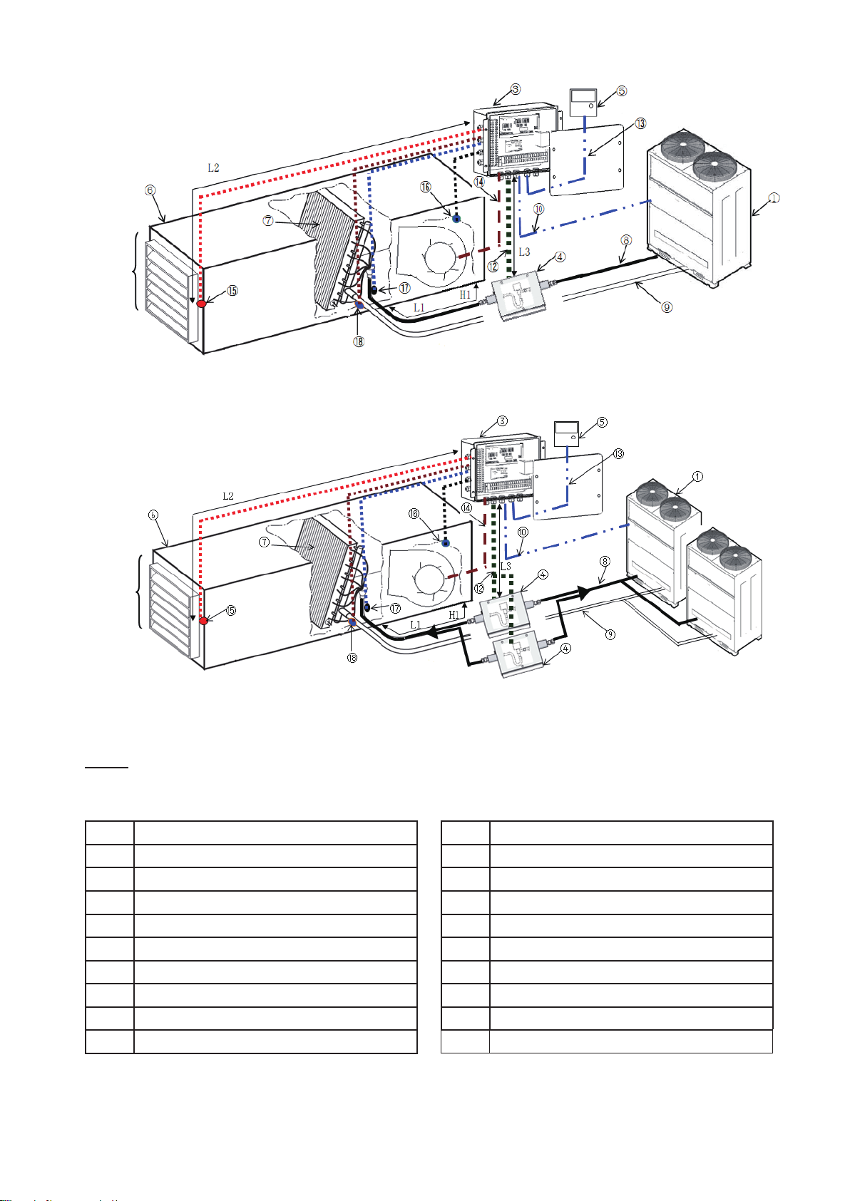
2.4 Limitation of Installation and AHU ..........................................................................................................9
2.5 CapacityControlMode......................................................................................................................... 11
3 Transportation and Handling.........................................................................................................................16
3.1 Transportation ......................................................................................................................................16
3.2 Installation Location..............................................................................................................................16
3.3 Dimension Data....................................................................................................................................16
3.4 Installation Method ...............................................................................................................................16
3.5 ThermistorInstallation..........................................................................................................................18
4 Refrigerant Piping Work................................................................................................................................19
4.1 Piping Materials....................................................................................................................................19
4.2 Piping Connection ................................................................................................................................19
5 ElectricalWiring ............................................................................................................................................20
5.1 GeneralCheck .....................................................................................................................................20
5.2 ElectricalWiringConnection ................................................................................................................20
5.3 ControlBoxTerminalBlock ..................................................................................................................21
5.4 ExpansionValveBox............................................................................................................................21
5.5 TerminalBlockConnectionandRemarks ............................................................................................22
6 OptionalSettingandInput/OutputSetting ....................................................................................................23
6.1 OptionalSettingandInput/OutputSettingonWiredController............................................................23
6.2 InitializationofOptionalSettingandInput/OutputSettingbyWiredController ....................................23
6.3 OptionalSettingandInput/OutputSetting............................................................................................23
6.4 InputSetting .........................................................................................................................................26
6.4.1 RemoteControlON/OFFFunction .............................................................................................26
6.4.2 ControlbyField-SuppliedRoomThermostat(Settingindication01/02).....................................29
6.4.3 CoolingorHeatingOperationModeSetting(Settingindication07) ...........................................30
6.5 OutputSetting ......................................................................................................................................31
7 Setting of DIP Switches ................................................................................................................................32
8 Test Run........................................................................................................................................................33
9 Warranty Policy and Disclaimer ....................................................................................................................33


 null")