manuals.online logo
Brands
  1. Home
  2. •
  3. Brands
  4. •
  5. Hitachi
  6. •
  7. Air Conditioner
  8. •
  9. Hitachi RAS-NP4US Manual

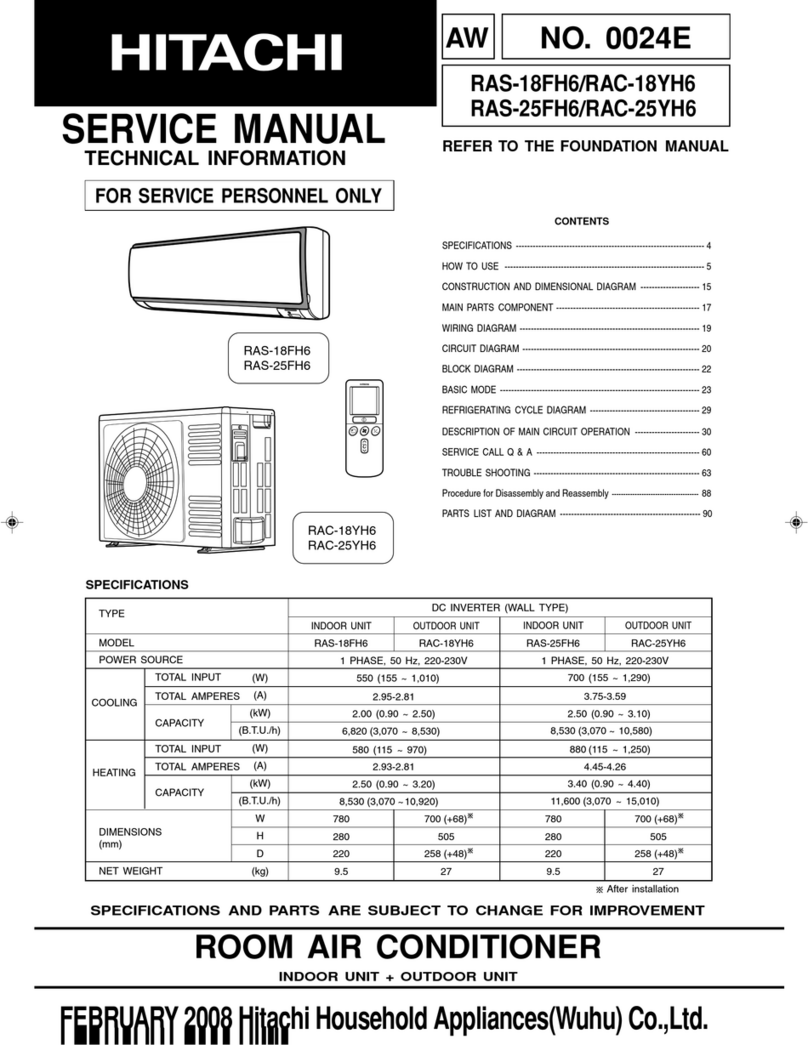
Hitachi RAS-NP4US Manual

This manual suits for next models

15

Other Hitachi Air Conditioner manuals

Hitachi RAM-40QH5 User manual

Hitachi

Hitachi RAM-40QH5 User manual

Hitachi RPF Series User manual

Hitachi

Hitachi RPF Series User manual

Hitachi RAC-18WPA User manual

Hitachi

Hitachi RAC-18WPA User manual

Hitachi UTOPIA RAS-4 Series User manual

Hitachi

Hitachi UTOPIA RAS-4 Series User manual

Hitachi RAK-25NH6 User manual

Hitachi

Hitachi RAK-25NH6 User manual

Hitachi RAK-18NH6AS User manual

Hitachi

Hitachi RAK-18NH6AS User manual

Hitachi air Home 400 RAK-DJ60PHAE User manual

Hitachi

Hitachi air Home 400 RAK-DJ60PHAE User manual

Hitachi RA-06SR User manual

Hitachi

Hitachi RA-06SR User manual

Hitachi RAC-60YH7 User manual

Hitachi

Hitachi RAC-60YH7 User manual

Hitachi RAK-15QPD User manual

Hitachi

Hitachi RAK-15QPD User manual

Hitachi RPC-(1.5-6.0)FSN3 User manual

Hitachi

Hitachi RPC-(1.5-6.0)FSN3 User manual

Hitachi airHome 300 QH Series User manual

Hitachi

Hitachi airHome 300 QH Series User manual

Hitachi RAS-(3-6)HVRNM2E User manual

Hitachi

Hitachi RAS-(3-6)HVRNM2E User manual

Hitachi RAS-X18CBT User manual

Hitachi

Hitachi RAS-X18CBT User manual

Hitachi RAS-S10CYT User manual

Hitachi

Hitachi RAS-S10CYT User manual

Hitachi PHKM050SAH1 User manual

Hitachi

Hitachi PHKM050SAH1 User manual

Hitachi RAS-08CH9 User manual

Hitachi

Hitachi RAS-08CH9 User manual

Hitachi RAF-50FX8 User manual

Hitachi

Hitachi RAF-50FX8 User manual

Hitachi RAS-ME09HX1 User manual

Hitachi

Hitachi RAS-ME09HX1 User manual

Hitachi RAD-25RPA User manual

Hitachi

Hitachi RAD-25RPA User manual

Hitachi RAD-70PPD User manual

Hitachi

Hitachi RAD-70PPD User manual

Hitachi RCI-1.5UNE1NH Manual

Hitachi

Hitachi RCI-1.5UNE1NH Manual

Hitachi RAC-P25YHAB User manual

Hitachi

Hitachi RAC-P25YHAB User manual

Hitachi RAS-35FH6 User manual

Hitachi

Hitachi RAS-35FH6 User manual

Popular Air Conditioner manuals by other brands

Fujitsu ASYG 09 LLCA installation manual

Fujitsu

Fujitsu ASYG 09 LLCA installation manual

York HVHC 07-12DS Installation & owner's manual

York

York HVHC 07-12DS Installation & owner's manual

Carrier Fan Coil 42B Installation, operation and maintenance manual

Carrier

Carrier Fan Coil 42B Installation, operation and maintenance manual

intensity IDUFCI60KC-3 installation manual

intensity

intensity IDUFCI60KC-3 installation manual

Frigidaire FAC064K7A2 Factory parts catalog

Frigidaire

Frigidaire FAC064K7A2 Factory parts catalog

Sanyo KS2432 instruction manual

Sanyo

Sanyo KS2432 instruction manual

LG MultiV Series installation manual

LG

LG MultiV Series installation manual

CLIMAVENETA a-CHD U-2T 606+2209 OPERATING AND INSTALLATION Manual

CLIMAVENETA

CLIMAVENETA a-CHD U-2T 606+2209 OPERATING AND INSTALLATION Manual

Midea EWK06CW5 user manual

Midea

Midea EWK06CW5 user manual

Pioneer FAB Series installation manual

Pioneer

Pioneer FAB Series installation manual

SPT WA-1511S user manual

SPT

SPT WA-1511S user manual

Mitsubishi Electric Mr.Slim MSZ-A24NA operating instructions

Mitsubishi Electric

Mitsubishi Electric Mr.Slim MSZ-A24NA operating instructions

Mitsubishi Electric PUHZ-RP50VHA4 Service manual

Mitsubishi Electric

Mitsubishi Electric PUHZ-RP50VHA4 Service manual

Panasonic CS-S18HKQ Service manual

Panasonic

Panasonic CS-S18HKQ Service manual

Panasonic CS-E15NKE3 operating instructions

Panasonic

Panasonic CS-E15NKE3 operating instructions

Gree GWH18TC-K3DNA1B/I Service manual

Gree

Gree GWH18TC-K3DNA1B/I Service manual

Friedrich ZoneAire Compact P08SA owner's manual

Friedrich

Friedrich ZoneAire Compact P08SA owner's manual

Daikin R32 Split Series installation manual

Daikin

Daikin R32 Split Series installation manual

manuals.online logo
manuals.online logoBrands
  • About & Mission
  • Contact us
  • Privacy Policy
  • Terms and Conditions

Copyright 2025 Manuals.Online. All Rights Reserved.

Installation, Operation and Maintenance
INSTRUCTIONS MANUAL
SPLIT-SYSTEM
AIR CONDITIONERS
Models:
::
:
Cooling Units Condensing Units
RAS-NP4US + RAS-NP4CTS
RAS-NP5US + RAS-NP5CTS
RAS-NP6US + RAS-NP6CTS
RAS-NP8US + RAS-NP8CTS
RAS-NP9US + RAS-NP9CTS
RAS-NP10US + RAS-NP10CTS
RAS-NP13US + RAS-NP13CTS
RAS-NP15US + RAS-NP15CTS
REFRIGERANT:R410A
IMPORTANT:
READ AND UNDERSTAND THIS
INSTRUCTION MANUAL BEFORE
USING THIS AIR CONDITIONER.
KEEP THIS MANUAL FOR FUTURE
REFERENCE.
65MP31
96
IMPORTANT NOTICE
˗HITACHI pursues a policy of continuing improvement in design and performance of products. The
right is therefore reserved to vary specification without notice.
˗HITACHI cannot anticipate every possible circumstance that might involve a potential hazard.
˗No part of this manual may be reproduced without written permission.
˗Signal words (DANGER, WARNING and CAUTION)are used to identify levels of hazard
seriousness. Definitions for identifying hazard levels are provided below with their respective signal
words.
Immediate hazards which WILL result in severe personal injury or
death.
Hazards or unsafe practices which COULD result in severs personal
injury or death.
Hazards or unsafe practices which COULD result in minor personal
injury or product or property damage.
Useful information for this operation and/or maintenance.
˗If you have any questions, contact your contractor or dealer of HITACHI.
˗This manual gives a common description and information for this air conditioner which you operate
as well as for other models.
˗This air conditioner has been designed for the following temperatures. Operate the air conditioner
within this range.
Condenser Air Inlet Temperature and Evaporator Air Inlet Temperature
Model
Condenser Air Inlet Temperature
-
Dry Bulb
-
Evaporator Air Inlet Temperature
-
Dry/Wet Bulb
-
Maximum
Minimum
Maxi
mum
Minimum
All Models 52°C
125°F
20°C
68°F
35°C / 21.5°C
95°F / 70.5°F
19.5°C / 14°C
67°F / 57°F
NOTES:
1. When the unit is operating at a condenser air inlet temperature of 52°C DB (125°F DB), the
maximum evaporator air inlet temperature shall be 18°C WB (64.4°F WB).
2. All models: 80% to 120% of Nominal Air Flow.
Hitachi’s air conditioners are designed and manufactured based on using the specified refrigerants. The applicable
refrigerants are specified to each unit models. However, in the global sites, it is revealed that charging different type
of refrigerants instead of the specified refrigerants. This action may cause mechanical troubles, malfunction and
failure, and in the worst case, it endangers safety seriously and may cause a fire or an explosion.
Therefore, Do Not charge the non-specified refrigerants or others in the refrigerant cycle of the unit as follows:
˗Hydrocarbon Refrigerants such as Propane or etc.
˗Oxygen, Flammable Gases such as Acetylene or etc.
˗Poisonous Gases.
The types of charging refrigerants are indicated in the Installation and Maintenance Manuals, Technical Catalogs,
Service Manuals and the specification label in the each unit. Be aware that Hitachi does not take any
responsibility for unit failure, troubles of malfunction, and any accidents caused by charging the
non-specified refrigerants or others such as above.
DANGER
炰
烉
ˏDANGER
炰
ˏ
WARNING
炰
烉
ˏCAUTION
炰
烉
NOTE
烉
OPERATION INSTRUCTIONS HITACHI Split-System Air Conditioners
For Combined Models: RAS-NP4US+RAS-NP4CTS
RAS-NP5US+RAS-NP5CTS
RAS-NP6US+RAS-NP6CTS
RAS-NP8US+RAS-NP8CTS
RAS-NP9US+RAS-NP9CTS
RAS-NP10US+RAS-NP10CTS
RAS-NP13US+RAS-NP13CTS
RAS-NP15US+RAS-NP15CTS
Starting Procedures
1. Switch ON the main power source to the
unit.
2. Set the operation switch of the room
thermostat to the desired operation position.
FAN-Ventilation Operation
COOL-Cooling Operation
3. Set the thermostat knob of the room
thermostat to the desired temperature.
4. Set the system switch of the room thermostat
to the ON position.
Stopping Procedures
1. Set the operation switch to the OFF position.
2. Switch OFF the main power source to the
unit. Please contact your service shop if the
trouble is still not solved.
Maintenance
1. Clean or replace the filter.
2. Clean the cabinet with cleaner.
3. Clean the condensate drain pan and the drain
piping.
4. Clean the condenser. It is recommended that a
specialist be contacted for this type of work.
5. Check for abnormal sounds and vibration.
Stop the unit and contact your service shop, if
observed.
Troubleshooting
Unit Does Not Start
1. Is the main power source switch to the unit
ON?
2. Is the main fuse normal?
3. Is the phase of main power source right?
Poor Cooling Operation
1. Are there any obstacles, which hamper
sufficient air to the condenser?
2. Check to ensure that the thermostat is set at
the desired position
3. Check the air filter for clogging.
4. Are there any obstacles, which hamper free
air
flow to the room thermostat?
IMPORTANT NOTICE
˗HITACHI pursues a policy of continuing improvement in design and performance of products. The
right is therefore reserved to vary specification without notice.
˗HITACHI cannot anticipate every possible circumstance that might involve a potential hazard.
˗No part of this manual may be reproduced without written permission.
˗Signal words (DANGER, WARNING and CAUTION)are used to identify levels of hazard
seriousness. Definitions for identifying hazard levels are provided below with their respective signal
words.
Immediate hazards which WILL result in severe personal injury or
death.
Hazards or unsafe practices which COULD result in severs personal
injury or death.
Hazards or unsafe practices which COULD result in minor personal
injury or product or property damage.
Useful information for this operation and/or maintenance.
˗If you have any questions, contact your contractor or dealer of HITACHI.
˗This manual gives a common description and information for this air conditioner which you operate
as well as for other models.
˗This air conditioner has been designed for the following temperatures. Operate the air conditioner
within this range.
Condenser Air Inlet Temperature and Evaporator Air Inlet Temperature
Model
Condenser Air Inlet Temperature
-
Dry Bulb
-
Evaporator Air Inlet Temperature
-
Dry/Wet Bulb
-
Maximum
Minimum
Maxi
mum
Minimum
All Models 52°C
125°F
20°C
68°F
35°C / 21.5°C
95°F / 70.5°F
19.5°C / 14°C
67°F / 57°F
NOTES:
1. When the unit is operating at a condenser air inlet temperature of 52°C DB (125°F DB), the
maximum evaporator air inlet temperature shall be 18°C WB (64.4°F WB).
2. RUA-NP4ATS,RUA-NP5ATS,RUA-NP9ATS and RUA-NP10ATS: 80% to 120% of Nominal
Air Flow.RUA-NP6ATS and RUA-NP8ATS: 80% to 115% of Nominal Air Flow.
Hitachi’s air conditioners are designed and manufactured based on using the specified refrigerants. The applicable
refrigerants are specified to each unit models. However, in the global sites, it is revealed that charging different type
of refrigerants instead of the specified refrigerants. This action may cause mechanical troubles, malfunction and
failure, and in the worst case, it endangers safety seriously and may cause a fire or an explosion.
Therefore, Do Not charge the non-specified refrigerants or others in the refrigerant cycle of the unit as follows:
˗Hydrocarbon Refrigerants such as Propane or etc.
˗Oxygen, Flammable Gases such as Acetylene or etc.
˗Poisonous Gases.
The types of charging refrigerants are indicated in the Installation and Maintenance Manuals, Technical Catalogs,
Service Manuals and the specification label in the each unit. Be aware that Hitachi does not take any
responsibility for unit failure, troubles of malfunction, and any accidents caused by charging the
non-specified refrigerants or others such as above.
DANGER
炰
烉
ˏDANGER
炰
ˏ
WARNING
炰
烉
ˏCAUTION
炰
烉
NOTE
烉
HITACHI Split-System Air Conditioners Cooling Units
Models: RAS-NP4US through RAS-NP15US
RAS-NP4US and RAS-NP5US
1. Return Air Connection
2. Supply Air Connection
3. Refrigerant Piping Connection
for Liquid Line
4. Refrigerant Piping Connection
for Gas Line
5. Hole for Power Supply
6. Condensate Drain Connection
RAS-NP9US and RAS-NP10US
RAS-NP6US and RAS-NP8US RAS-NP13US and RAS-NP15US
RAS-13NPCTS and RAS-NP15CTS
RAS-NP4CTS and RAS-NP5CTS
HITACHI Split-System Air Conditioners Condensing Units
Models: RAS-NP4CTS through RAS-NP15CTS
RAS-NP6CTS and RAS-NP8CTS
1. Condenser Air Intake
2. Condenser Air Discharge
3. Refrigerant Piping Connection
for Liquid Line
4. Refrigerant Piping Connection
for Gas Line
5. Hole for Power Supply
6. Hole for Control Circuit
7. Service Panel
RAS-NP9CTS and RAS-NP10CTS
1
PREPARATION
Preparation
Initial Check
Required Materials - Measure, Architectural Information, Regarding Installation Location.
Installation Location - Confirm that the final installation location is available for convenient piping,
wiring and ducting work. Strong water runoff should be avoided.
Installation Space - Check for obstacles which restrict air flow or hamper maintenance work in the
space specified in Fig. 1.
Foundation - Make sure the foundation is smooth, horizontal and sufficiently strong, taking into
account the maximum foundation gradient Fig. 2. and the unit weight balance Fig. 3-1 and Fig. 3-2.
Cooling Unit
Confirm elevation provision for the unit on a solid base with an iron frame or concrete curbs in order to
obtain proper clearance beneath the unit or confirm suspension provision for the unit shown in Fig.
4-1.
Condensing Unit
Confirm elevation provision for the unit on a solid base with an iron frame or concrete curbs shown in
Fig. 4-2. in order to obtain proper clearance beneath the unit for either rooftop or on-the-ground
installation. Additionally, for on-the-ground installation, provide a gravel or concrete space around the
condenser air intake, in order to avoid air flow obstruction due to grass or other vegetation.
Unit - Check to ensure that the unit has been transported without damage. File a damage claim with
the transportation companies if mishandling due to transportation company negligence is suspected.
Transportation - secure the route to the final installation location by confirming the packing
dimensions (see “Unit General Data” in Technical CatalogⅠ).
2
Refrigerant Piping
Connection Side
700mm
700mm
INSTALLATION SPACE
Installation Space
Cooling Units Condensing Units
RAS-NP4US through RAS-NP8US RAS-NP4CTS through RAS-NP10CTS
RAS-NP9US through RAS-NP15US RAS-NP13CTS and RAS-NP15CTS
Fig. 1.
Installation
Space
3
MAXIMUM FOUNDATION GRADIENT
Maximum Foundation Gradient
Cooling Units
Condensing Units
Fig.2 Maximum Foundation Gradient
Model Dimensions
A B
deg. mm deg. mm
RAS-NP4US 0.6 10 0.6 10
RAS-NP5US 0.6 10 0.6 10
RAS-NP6US 0.6 10 0.6 12
RAS-NP8US 0.6 10 0.6 15
RAS-NP9US 0.6 10 0.6 16
RAS-NP10US
0.6 10 0.6 16
RAS-NP13US
0.6 15 0.6 16
RAS-NP15US
0.6 15 0.6 16
Model Dimensions
A B
deg. mm deg. mm
RAS-NP4CTS
1.0 14 1.0 17
RAS-NP5CTS
1.0 14 1.0 17
RAS-NP6CTS
1.0 19 1.0 23
RAS-NP8CTS
1.0 19 1.0 23
RAS-NP9CTS
1.0 22 1.0 23
RAS-NP10CTS
1.0 22 1.0 23
Model Dimensions
A B
deg. mm deg. mm
RAS-NP13CTS
1.0 38 1.0 21
RAS-NP15CTS
1.0 38 1.0 21
4
WEIGHT BALANCE
Weight Balance
Cooling Units
Model Dimensions (mm) Approximate
Operating
Weight (kg)
A B C D
RAS-NP4US
510
610
970
1,130
90
RAS-NP5US
510
610
970
1,130
95
RAS-NP6US
600
610
1,150
1,130
120
RAS-NP8US
750
610
1,430
1,130
130
RAS-NP9US
800
610
1,530
1,130
145
RAS-NP10US
800
610
1,530
1,130
150
RAS-NP13US
820
830
1,560
1,530
200
RAS-NP15US
820
830
1,560
1,530
210
◎
◎◎
◎:
::
:Center of Gravity
Fig.3-1 Weight Balance