Ai
ln,
ae
aa
PRODUCT
SAFETY
NOTICE
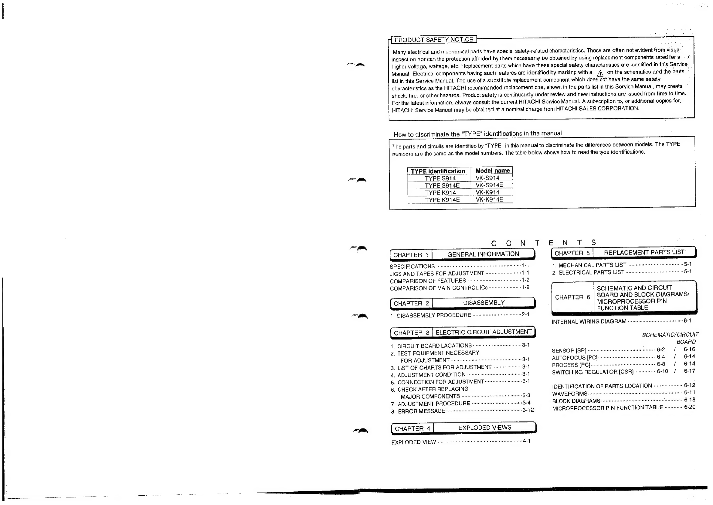
_TYPE
identification
|
Model
name
TYPE
$914
VK-8914
|
TYPE
S914E___|_
VK-S914E
TYPEK914___|_
VK-K914
TYPE
K914E
VK-K914E
Cc
ON
T
CHAPTER
1
GENERAL
INFORMATION
SPECIFICATIONS
oss
svssssscusstsnseenersnseeeteeneaeeeresse
t4
JIGS
AND
TAPES
FOR
ADJUSTMENT
«
COMPARISON
OF
FEATURES
“4-2
COMPARISON
OF
MAIN
CONTROL
ICS
vrrrveerrrerrsee
1-2
CHAPTER
2
DISASSEMBLY
)
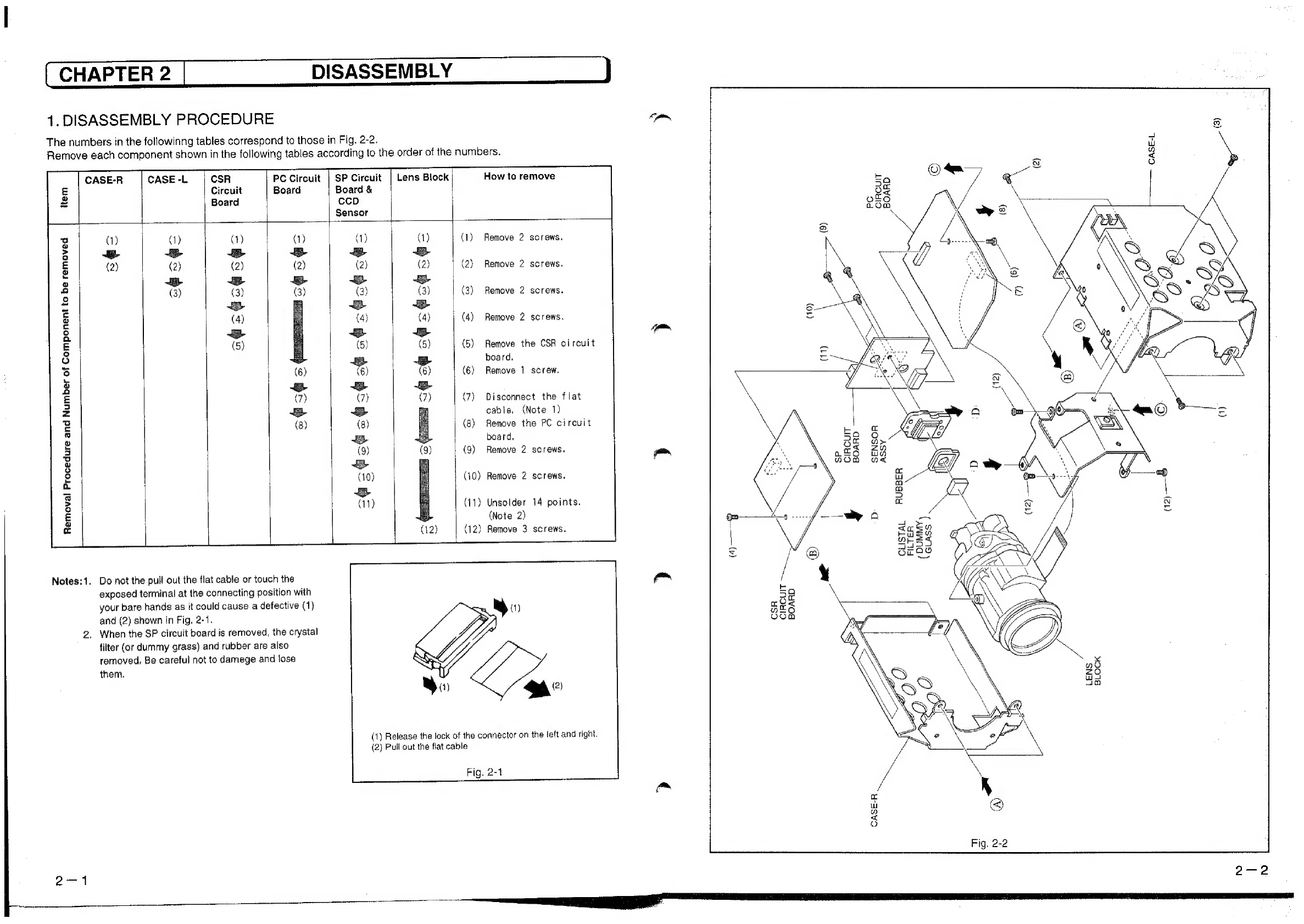
1.
DISASSEMBLY
PROCEDURE
svvvrsesstsrtereresteererscee
2-1
CHAPTER
3
|
ELECTRIC
CIRCUIT
ADJUSTMENT
1,
CIRCUIT
BOARD
LACATIONS
-ivvscseretstesrenrerierreens
3-1
2.
TEST
EQUIPMENT
NECESSARY
FOR
ADJUSTMENT
«sete
3-4
3.
LIST
OF
CHARTS
FOR
ADJUSTMENT
4,
ADJUSTMENT
CONDITION
”
5.
CONNECTION
FOR
ADJUSTMENT
vrvrerverserersttereeee
3-1
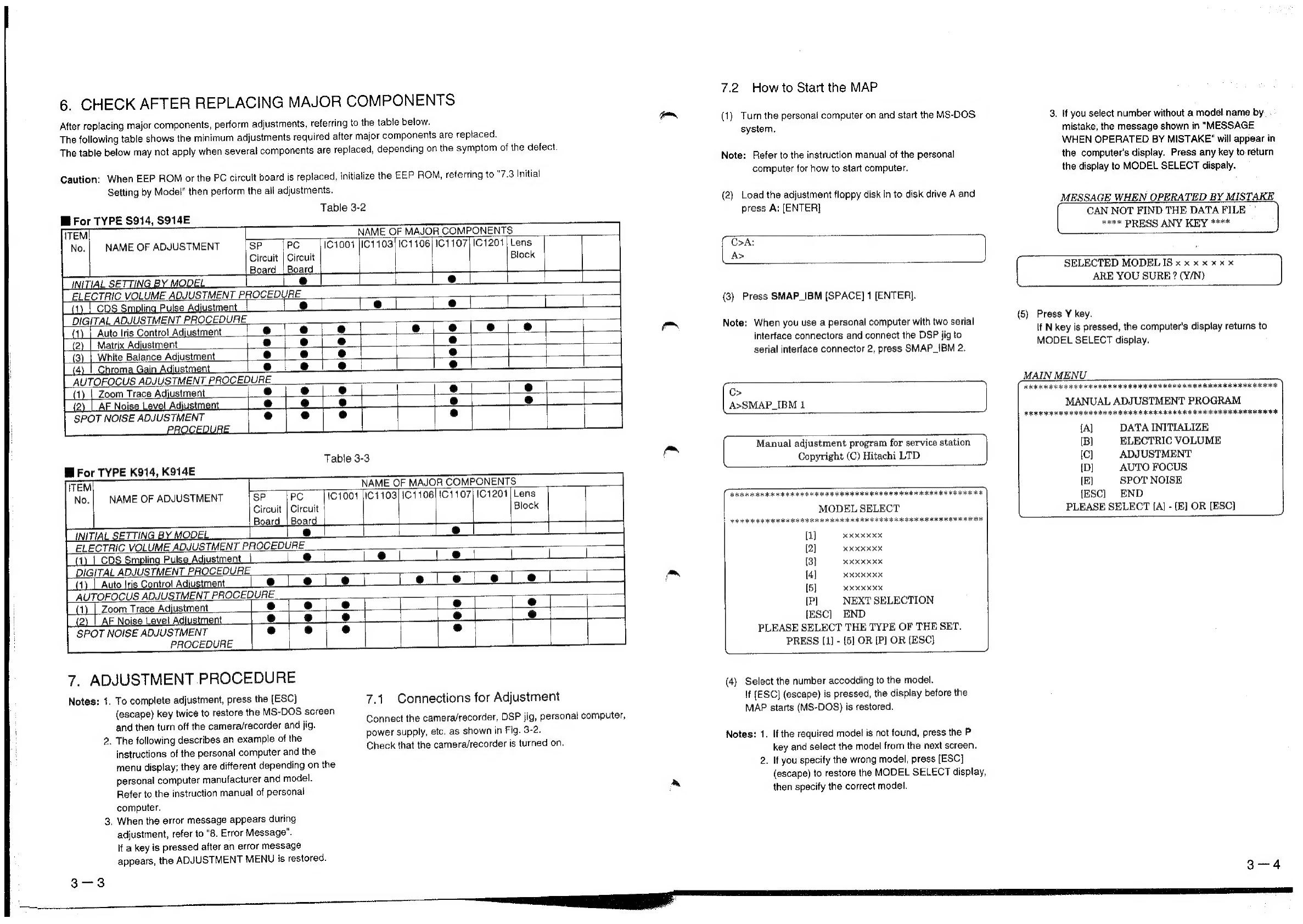
6.
CHECK
AFTER
REPLACING
MAJOR
COMPONENTS
ovrvesrsrsrerrerrsstsesetsreereseeees
3-3
.
ADJUSTMENT
PROCEDURE
.
.
ERROR
MESSAGE
CHAPTER
4
EXPLODED
VIEWS
EXPLODED
VIEW
voces
ssesssenressrisescsneenennnrennentestencons
44
aon
Many
electrical
and
mechanical
parts
have
special
safety-related
characteristics.
These
are
often
not
evident
from
visual
inspection
nor
can
the
protection
afforded
by
them
necessarily
be
obtained
by
using
replacement
components
rated
fora
higher
voltage,
wattage,
etc.
Replacement
parts
which
have
these
special
safety
characteristics
are
identified
in
this
Service
Manual.
Electrical
components
having
such
features
are
identified
by
marking
with
a
c
ey
list
in
this
Service
Manual.
The
use
of
a
substitute
replacement
component
which
does
not
have
the
same
safety
characteristics
as
the
HITACHI
recommended
replacement
one,
shown
in
the
parts
list
in
this
Service
Manual,
may
create
shock,
fire,
or
other
hazards.
Product
safety
is
continuously
under
review
and
new
instructions
are
issued
from
time
to
time.
For
the
latest
information,
always
consult
the
current
HITACHI
Service
Manual.
A
subscription
to,
or
additional
copies
for,
HITACHI
Service
Manual
may
be
obtained
at
a
nominal
charge
trom
HITACHI
SALES
CORPORATION.
The
parts
and
circuits
are
identified
by
"TYPE"
in
this
manual
to
discriminate
the
differences
between
models.
The
TYPE
numbers
are
the
same
as
the
model
numbers.
The
table
below
shows
how
to
read
the
type
identifications.
on
the
schematics
and
the
parts”
How
to
discriminate
the
"TYPE"
identifications
in
the
manual
EN
T
8S
CHAPTER
5
REPLACEMENT
PARTS
LIST
1,
MECHANICAL
PARTS
LIST
2.
ELECTRICAL
PARTS
LIST
vv-errerrre
SCHEMATIC
AND
CIRCUIT
CHAPTER
6
|
BOARD
AND
BLOCK
DIAGRAMS/
MICROPROCESSOR
PIN
FUNCTION
TABLE
INTERNAL
WIRING
DIAGRAM
-s-ssssssseeseessessetnstetesne
6-1
SCHEMATIC/CIRCUIT
BOARD
SENSOR
[SP]
|
6-16
AUTOFOCUS
[PC]
[6-14
PROCESS
[PC]---
oe
1
B14
SWITCHING
REGULATOR
[CSR]
---s+-+-
6-10
/
6-17
IDENTIFICATION
OF
PARTS
LOCATION
612
WAVEFORMS:.--»-+-
BLOCK
DIAGRAMS.
ee
MICROPROCESSOR
PIN
FUNCTION
TABLE
+--+"
6-20