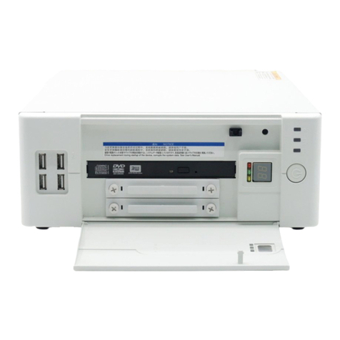
Hitachi HF-W6500 60 User manual

USER’S
MANUAL
HITACHI INDUSTRIAL COMPUTER
HF-W6500Model 60
RAS FEATURES MANUAL
WIN-63-0100-03

USER’S
MANUAL
HITACHI INDUSTRIAL COMPUTER
HF-W6500Model 60
RAS FEATURES MANUAL
WIN-63-0100-03
Read and Keep this manual.
•Read safety instructions carefully and understand
them before starting your operation.
•Keep this manual at hand for reference.

First Edition, October 2021, WIN-63-0100 (out of print)
Second Edition, June 2022, WIN-63-0100-01 (out of print)
Third Edition, October 2023, WIN-63-0100-02 (out of print)
Fourth Edition, January 2024, WIN-63-0100-03
All Rights Reserved, Copyright © 2021, 2024, Hitachi, Ltd.
The contents of this publication may be revised without prior notice.
No part of this publication may be reproduced in any form or by any means without permission in
writing from the publisher.
Printed in Japan.
TP<IC> (FL-MW2007)

S-1
SAFETY INSTRUCTIONS
Carefully read and fully understand the safety precautions below before operating
the equipment.
⚫Operate the equipment by following the instructions and procedures described
in this manual.
⚫Pay attention especially to safety precautions displayed on the equipment or in
this manual. Make sure you follow them. Otherwise, personal injury and
property damage including damage to the equipment may result.
⚫A safety precaution is indicated by a heading as shown below. A heading is
either a safety alert symbol; a word such as “DANGER”, “WARNING”,
“CAUTION”, or “NOTICE”; or a combination of both.
This is a safety alert symbol. This symbol is used to signify
potential hazards that may result in personal injury or death.
Make sure you follow the safety message that follows this
symbol in order to avoid possible injury or death.
DANGER: This symbol is used to indicate imminent hazards that
will highly likely result in serious personal injury or
death.
WARNING: This symbol is used to indicate potential hazards that
may result in serious personal injury or death.
CAUTION: This symbol is used to indicate potential hazards that
may result in minor or moderate personal injury.
NOTICE:This symbol is used to indicate hazards that may result in
equipment or property damage but not personal injury.
The heading “NOTE”is used to indicate a cautionary note about handling and
operation of the equipment.
⚫Do not attempt to perform any operation that is not described in this manual. If
there is any problem with the equipment, call your maintenance personnel.
⚫Read this manual carefully and fully understand the directions and precautions
written in this manual before operating the equipment.
⚫Keep this manual nearby so that you can reference the manual anytime you
need it.
⚫Every effort has been made to specify the best precautions on the equipment
and in the manual. Nevertheless, unexpected incidents may occur. When you
use the equipment, you are asked not only to follow the instructions but also to
use your own judgement on safety.

S-2
SAFETY INSTRUCTIONS (Continued)
1. SAFETY WARNINGS IN THIS MANUAL
1.1 Safety Warning Indicated as “NOTICE”
⚫When failure of a drive is predicted, a drive hardware failure is likely to
occur in the near future. We recommend you to back up the data and replace
the drive. For information about how to replace a drive, refer to “HF-W6500
Model 60 INSTRUCTION MANUAL (manual number WIN-62-0074)”.
(See page 2-3.)
⚫When OS hung-up occurs, processes on the OS cannot run as scheduled, and
the facility using this equipment may be affected due to delay in processing.
If OS hung-up occurs, resolve it immediately. (See page 2-6.)
●If a RAS MCU fails, the RAS software will not be able to monitor and
control the hardware correctly. Stop the equipment and then contact your
system administrator or maintenance personnel. (See page 2-15.)
⚫If this equipment continues to operate while fan failure is detected, internal
parts such as a processor are not cooled down sufficiently, and that may
cause thermal runaway of the system due to malfunction of the equipment or
result in damage to the parts. (See page 3-4.)
⚫When the Hardware status window shows an error in hardware, resolve the
error immediately. (See page 4-2.)
⚫When failure of a drive is anticipated, the drive may experience hardware
failure in near future. We recommend you to back up the data and replace the
drive. For information about how to replace a drive, refer to “HF-W6500
Model 60 INSTRUCTION MANUAL (manual number WIN-62-0074)”.
(See page 4-10.)

S-3
SAFETY INSTRUCTIONS (Continued)
⚫If this equipment continues to operate after a fan failure is detected, internal
parts such as processors will not be cooled sufficiently. In such a case,
equipment malfunctions might occur, causing erratic system operation or
damage to components. If possible, enable the automatic shutdown feature.
⚫If the automatic shutdown feature is not used, have a user application detect a
fan failure using a RAS event and shut down the equipment. (See page 5-2.)
⚫Log function exits (asynchronously) without waiting for the data to be
actually written to a log file. That means this function does not return an
error even when writing to a log file fails for some reason. We recommend
important information be recorded in the OS event log. (See page 6-15.)
⚫CPU load increases while memory dump files are being collected. While
CPU load is high, operation of user applications can be disturbed. Make sure
that you do not collect memory dump files using the log information
collection window while the applications for business use are running on this
equipment. (See page 7-4.)
⚫While the equipment is running in simulation mode, monitoring of the actual
hardware status is disabled. Errors including fan failure and abnormal
temperature cannot be detected. You must never use this equipment in
simulation mode for business use. Use the simulation function only for
testing a user application and checking the notification interface of the RAS
software. (See page 8-2.)

i
PREFACE
This manual describes how to use the Reliability, Availability, Serviceability (RAS) feature of the
HITACHI INDUSTRIAL COMPUTER HF-W6500 Model 60 (hereinafter referred to as
“equipment”).
<Organization of this manual>
This manual is organized as follows.
CHAPTER 1 CAPABILITIES OF THE RAS FEATURE
CHAPTER 2 ITEMS MONITORED BY THE RAS FEATURE
CHAPTER 3 SETTING UP THE RAS FEATURE
CHAPTER 4 CHECKING THE HARDWARE STATUS
CHAPTER 5 CONTROLLING THE HARDWARE
CHAPTER 6 LIBRARY FUNCTIONS
CHAPTER 7 FEATURES RELATED TO MAINTENANCE AND FAILURE ANALYSIS
CHAPTER 8 SIMULATING THE HARDWARE STATUS
<Precautions when you use the RAS feature>
● Precautions about a RAS external contacts interface
This manual provides an explanation about a RAS external contacts interface. Note that this
interface is an optional feature.
● Precautions about an event log entry at the startup of the SNMP service
When you enable the SNMP service, a standard feature of Windows®, in order to use remote
notification, an error log entry with event ID 1500 may be recorded at the startup of the SNMP
service. This event log entry is recorded when SNMP trap notification has not been set up. Set
up the trap notification according to “4.5.3 Enabling the remote notification”.
● User Account Control
If User Account Control (UAC) is enabled in Windows® configuration, User Account Control
windows is displayed when you run application or command. In this case, click OK or
Continue.
<Trademarks>
•Microsoft®, Windows®, Windows Server®, Windows NT®, and Visual Basic® are trademarks
or registered trademarks of U.S. Microsoft Corporation in the United States and other countries.
• All other product names (software and hardware) not from Hitachi described in this manual are
registered trademarks, trademarks, or products of their respective owners.

ii
<Note for storage capacity calculations>
● Memory capacities and requirements, file sizes and storage requirements, etc. must be
calculated according to the formula 2n. The following examples show the results of such
calculations by 2n(to the right of the equals signs).
1 KB (kilobyte) = 1,024 bytes
1 MB (megabyte) = 1,048,576 bytes
1 GB (gigabyte) = 1,073,741,824 bytes
1 TB (terabyte) = 1,099,511,627,776 bytes
● As for disk capacities, they must be calculated using the formula 10n. Listed below are the
results of calculating the above example capacities using 10nin place of 2n.
1 KB (kilobyte) = 1,000 bytes
1 MB (megabyte) = 1,0002bytes
1 GB (gigabyte) = 1,0003bytes
1 TB (terabyte) = 1,0004bytes

iii
CONTENTS
SAFETY INSTRUCTIONS ......................................................................................... S-1
CHAPTER 1 CAPABILITIES OF THE RAS FEATURE ........................................ 1-1
CHAPTER 2 ITEMS MONITORED BY THE RAS FEATURE ............................ 2-1
2.1 Fan Monitoring .................................................................................................................... 2-1
2.2 Monitoring Temperature inside the Chassis ........................................................................ 2-2
2.3 Drive Failure Prediction Function (SMART Monitoring) ................................................... 2-3
2.4 Drive Usage Monitoring ...................................................................................................... 2-4
2.5 Memory Monitoring ............................................................................................................. 2-5
2.6 OS Hung-up Monitoring ...................................................................................................... 2-6
2.7 Watchdog Timer Monitoring ............................................................................................... 2-8
2.7.1 Automatic retriggering feature for a watchdog timer .................................................... 2-8
2.7.2 Using a watchdog timer for monitoring a user program ................................................ 2-9
2.8 RAID Monitoring [B/T Model only] ................................................................................. 2-11
2.8.1 State transition of the RAID ........................................................................................ 2-12
2.8.2 Note about media error ................................................................................................ 2-13
2.9 RAS MCU Failure Monitoring Function........................................................................... 2-15
CHAPTER 3 SETTING UP THE RAS FEATURE .................................................... 3-1
3.1 RAS Setup Windows ........................................................................................................... 3-1
3.1.1 Overview ........................................................................................................................ 3-1
3.1.2 Starting the RAS Setup window .................................................................................... 3-2
3.1.3 Using the RAS Setup window ....................................................................................... 3-3
3.1.4 Editing popup notification messages ........................................................................... 3-14
CHAPTER 4 CHECKING THE HARDWARE STATUS ........................................ 4-1
4.1 Hardware Status Window .................................................................................................... 4-2
4.1.1 Overview ........................................................................................................................ 4-2
4.1.2 Hardware status icon ...................................................................................................... 4-4
4.1.3 Hardware status window ................................................................................................ 4-8
4.2 RAS Event Notification ..................................................................................................... 4-14
4.2.1 Overview ...................................................................................................................... 4-14
4.2.2 Detecting an event ....................................................................................................... 4-14
4.2.3 Example of using event objects ................................................................................... 4-15
4.3 Popup Notification ............................................................................................................. 4-16
4.3.1 Overview ...................................................................................................................... 4-16
4.3.2 Messages to be displayed ............................................................................................. 4-17
4.3.3 Popup notification settings .......................................................................................... 4-17
4.4 Status Display Digital LEDs Function ............................................................................... 4-18
4.4.1 Overview ...................................................................................................................... 4-18
4.4.2 Status codes to be displayed ........................................................................................ 4-19
4.4.3 Status display modes .................................................................................................... 4-21
4.4.4 Priorities of displayed codes ........................................................................................ 4-22
4.4.5 Status display digital LEDs control functions ............................................................. 4-22
4.5 Remote Notification ........................................................................................................... 4-23
4.5.1 Overview ...................................................................................................................... 4-23

iv
4.5.2 Hardware conditions that can be acquired by using remote notification ..................... 4-24
4.5.3 Enabling the remote notification ................................................................................. 4-25
4.5.4 Objects in the extended MIB for HF-W ...................................................................... 4-31
4.5.5 Extended MIB file for HF-W ...................................................................................... 4-39
4.6 Status Acquisition by Using the RAS Library ................................................................... 4-40
CHAPTER 5 CONTROLLING THE HARDWARE .................................................. 5-1
5.1 Automatic Shutdown of the Equipment ............................................................................... 5-2
5.1.1 Automatic shutdown when detecting fan failure ........................................................... 5-2
5.1.2 Automatic shutdown when detecting abnormally high temperature ............................. 5-3
5.1.3 Automatic shutdown when a remote shutdown request through the contact input is
detected .......................................................................................................................... 5-3
5.2 Controlling the Hardware by Using the RAS Library ......................................................... 5-4
5.3 RAID Configuration Control Command (raidctrl) [B/T Model only] ................................. 5-5
CHAPTER 6 LIBRARY FUNCTIONS ......................................................................... 6-1
6.1 RAS Library ....................................................................................................................... 6-1
6.1.1 Overview ........................................................................................................................ 6-1
6.1.2 Shutdown function (BSSysShut) ................................................................................... 6-3
6.1.3 Watchdog timer control function (WdtControl) ............................................................ 6-4
6.1.4 Control functions for the general purpose external contact outputs
(GendoControl and GendoControlEx) ........................................................................... 6-8
6.1.5 Get functions for the general purpose external contact inputs
(GetGendi and GetGendiEx) ........................................................................................ 6-11
6.1.6 Log function (MConWriteMessage) ............................................................................ 6-14
6.1.7 Get function for the memory condition (GetMemStatus) ............................................ 6-16
6.1.8 Get function for the drive condition (hfwDiskStat) ..................................................... 6-18
6.1.9 Get function for the RAID status (hfwRaidStat) [B/T Model only] ............................ 6-20
6.1.10 Status display digital LEDs control functions
(SetStCode7seg, TurnOff7seg, SetMode7seg) ........................................................ 6-23
6.2 Sample Programs ............................................................................................................... 6-26
CHAPTER 7 FEATURES RELATED TO MAINTENANCE AND
FAILURE ANALYSIS ............................................................................. 7-1
7.1 Notifying the Cause of the STOP Error Code ...................................................................... 7-1
7.1.1 Overview ........................................................................................................................ 7-1
7.1.2 Supported causes of the STOP error code ..................................................................... 7-2
7.1.3 Event log ........................................................................................................................ 7-3
7.2 Log Information Collection Window ................................................................................... 7-4
7.2.1 Overview ........................................................................................................................ 7-4
7.2.2 Starting the log information collection window ............................................................ 7-4
7.2.3 Using the log information collection window ............................................................... 7-5
7.2.4 Finishing the log information collection window .......................................................... 7-7
7.3 Logging the Trend of the Temperature inside the Chassis .................................................. 7-8
7.3.1 Overview ........................................................................................................................ 7-8
7.3.2 Log files ......................................................................................................................... 7-8
7.3.3 Logging interval setup command ................................................................................ 7-10
CHAPTER 8 SIMULATING THE HARDWARE STATUS ................................... 8-1
8.1 Hardware Status Simulation ................................................................................................. 8-1
v
8.1.1 Overview ........................................................................................................................ 8-1
8.1.2 Using the simulation function ........................................................................................ 8-4
8.1.3 Precautions when you use the Simulation Tool window ............................................. 8-16
8.1.4 Event log entries .......................................................................................................... 8-17
8.1.5 Remote notification ..................................................................................................... 8-17

vi
FIGURES
Figure 1-1 RAS Setup Window ................................................................................................. 1-2
Figure 1-2 Hardware Status Icon ............................................................................................... 1-3
Figure 2-1 State of the Status Lamp and the CPUSTOP Contact .............................................. 2-7
Figure 2-2 Example of a Flow Chart of Monitoring the Operational State of a User
Program .................................................................................................................... 2-9
Figure 2-3 RAID Status Transitions ........................................................................................ 2-12
Figure 2-4 Example of a Message Box when a Media Error Occurs ...................................... 2-14
Figure 2-5 Example of the message box display when a failure is detected
in a RAS MCU ....................................................................................................... 2-15
Figure 3-1 RAS Setup Window ................................................................................................. 3-1
Figure 3-2 Items in the Shutdown Setting ................................................................................. 3-3
Figure 3-3 Items in Watchdog Timer Setting ............................................................................ 3-5
Figure 3-4 Items in the Drive Usage Monitoring Setting .......................................................... 3-7
Figure 3-5 Advanced Setting for the Drive Usage Monitoring ................................................. 3-8
Figure 3-6 Items in the Status Display Digital LEDs Setting .................................................. 3-10
Figure 3-7 Items in the Popup Notification Setting ................................................................. 3-11
Figure 3-8 Advanced Settings for the Popup Notification Setting .......................................... 3-12
Figure 3-9 Format of a Message Definition File ...................................................................... 3-14
Figure 4-1 Hardware Status Window ......................................................................................... 4-2
Figure 4-2 Example of Displaying the Description of an Icon (When the Hardware
Status Is Normal) ...................................................................................................... 4-7
Figure 4-3 Example of Displaying the Description of an Icon (When the Hardware
Status Has an Error) ................................................................................................. 4-7
Figure 4-4 Menu of the Hardware Status Icon ........................................................................... 4-7
Figure 4-5 Starting the Hardware Status Window ..................................................................... 4-8
Figure 4-6 Confirmation Message when Disconnecting the Drive in Drive Bay1 .................. 4-12
Figure 4-7 Hardware Status Window (Example of Error Case) .............................................. 4-13
Figure 4-8 Example of Popup Message ................................................................................... 4-16
Figure 4-9 Status Display Digital LEDs .................................................................................. 4-18
Figure 4-10 Hardware Status Codes ........................................................................................ 4-19
Figure 4-11 Application Status Code ....................................................................................... 4-20
Figure 4-12 STOP Error Code ................................................................................................. 4-20
Figure 4-13 Example of a Status Display Mode ...................................................................... 4-21
Figure 6-1 Behavior of the WDTTO Contact ............................................................................ 6-7
Figure 6-2 Behavior of the WDTTO Contact (When the OS Shuts Down) .............................. 6-7
Figure 6-3 Behavior of the GENDO0 Contact ......................................................................... 6-10
Figure 6-4 Format of Log Information .................................................................................... 6-14
Figure 7-1 Organization of the Folders for Collected Data ....................................................... 7-7
Figure 7-2 Format of Log Information 1 ................................................................................... 7-9
Figure 7-3 Format of Log Information 2 ................................................................................... 7-9
Figure 8-1 Simulation Tool Window ......................................................................................... 8-1
Figure 8-2 Procedure to Use the Simulation Mode .................................................................... 8-4
Figure 8-3 Description of Each Part in the Simulation Tool Window ....................................... 8-7

vii
TABLES
Table 1-1 Overview of the RAS Feature ................................................................................... 1-1
Table 2-1 State of the Equipment in Terms of Fan Monitoring and State of the MCALL
Contact ....................................................................................................................... 2-1
Table 2-2 State of the Equipment in Terms of Monitoring Temperature inside the Chassis
and State of the MCALL Contact .............................................................................. 2-2
Table 2-3 State of the Equipment in Terms of OS Hung-up Monitoring and State of the
Status Lamp ............................................................................................................... 2-6
Table 2-4 State of the Equipment in Terms of OS Hung-up Monitoring and State of the
CPUSTOP Contact .................................................................................................... 2-6
Table 2-5 Status of the RAID and State of the MCALL Contact ............................................ 2-11
Table 2-6 RAID Statuses and Their Descriptions .................................................................... 2-12
Table 3-1 Setup Items in the RAS Setup Window ..................................................................... 3-1
Table 3-2 Section Names and Defined Messages .................................................................... 3-15
Table 3-3 Items Displayed in the Object List for Each Option Selected in the Event List ..... 3-17
Table 4-1 Hardware Status Icon ................................................................................................. 4-6
Table 4-2 Fan Condition and Displayed Information ................................................................ 4-9
Table 4-3 Temperature Condition and Displayed Information .................................................. 4-9
Table 4-4 Drive Condition and Displayed Information ........................................................... 4-10
Table 4-5 Type of the Drive and Displayed Information ......................................................... 4-11
Table 4-6 RAID Status and Displayed Information ................................................................. 4-11
Table 4-7 Reported Events ....................................................................................................... 4-15
Table 4-8 Messages Displayed ................................................................................................ 4-17
Table 4-9 Hardware Status Codes ............................................................................................ 4-19
Table 4-10 Status Display Modes ............................................................................................ 4-21
Table 4-11 Priorities of Hardware Status Display mode ......................................................... 4-22
Table 4-12 Priorities of Application Status Display mode ...................................................... 4-22
Table 4-13 Objects Related to the Hardware Status ................................................................ 4-31
Table 4-14 Objects Related to the RAS Function Settings ...................................................... 4-34
Table 4-15 Objects Related to Operational Modes .................................................................. 4-34
Table 4-16 Objects Related to the Extended MIB for HF-W .................................................. 4-35
Table 4-17 Objects Related to the Trap Notification (When an Error Occurs) ....................... 4-36
Table 4-18 Objects Related to the Trap Notification (When the Equipment Has Recovered
from an Error) ........................................................................................................ 4-37
Table 4-19 Objects Related to the Trap Notification (Operational Modes) ............................ 4-38
Table 5-1 RAID Status Displayed in the Output of the raidctrl Command ............................... 5-6
Table 5-2 Drive Status Displayed in the Output of the raidctrl Command ................................ 5-6
Table 5-3 Error Messages of the raidctrl Command .................................................................. 5-9
Table 6-1 RAS Library Functions .............................................................................................. 6-1
Table 6-2 List of Actions of WdtControl Specified by dwCmd ................................................ 6-4
Table 6-3 List of Actions of the GendoControl Function Specified by dwCmd ....................... 6-8
Table 6-4 List of Actions of the GendoControlEx Function Specified by dwPort .................... 6-9
Table 6-5 List of Actions of the GendoControlEx Function Specified by dwCmd ................... 6-9
Table 6-6 List of Actions of the GetGendiEx Function Specified by dwPort ......................... 6-12
Table 6-7 List of Values Stored in Dimm_Status .................................................................... 6-16
Table 6-8 List of Values Stored in Each Element of the HDD_PREDICT_DATA
Structure ................................................................................................................... 6-18
Table 6-9 List of Values Stored in Disk_Status ....................................................................... 6-20
Table 6-10 List of Define directive .......................................................................................... 6-21

viii
Table 6-11 Values Stored in Level in the HFW_ARRAY_STATUS Structure ...................... 6-24
Table 6-12 Values Stored in DiskNumber in the HFW_ARRAY_STATUS Structure .......... 6-24
Table 6-13 Values Stored in Status in the HFW_ARRAY_STATUS Structure ..................... 6-24
Table 6-14 Possible Combinations that Can Be Stored in Status in the
HFW_ARRAY_STATUS Structure ...................................................................... 6-25
Table 6-15 Values Stored in Each Element of the RAID_DATA Structure ........................... 6-26
Table 6-16 List of Values Specified by dwMode in the SetMode7seg Function .................... 6-30
Table 6-17 List of Provided Sample Programs ........................................................................ 6-31
Table 7-1 Supported STOP Error Causes .................................................................................. 7-2
Table 7-2 Event Log Entries Recorded by This Function ......................................................... 7-3
Table 7-3 Log Files .................................................................................................................... 7-8
Table 8-1 Event Log Entries Recorded by This Function ....................................................... 8-17

1. CAPABILITIES OF THE RAS FEATURE
1-1
CHAPTER 1 CAPABILITIES OF THE RAS FEATURE
The HF-W series come with the Reliability, Availability, Serviceability (RAS) feature that you
would expect from a highly reliable industrial computer.
The following is an overview of the RAS feature.
Table 1-1 Overview of the RAS Feature
Category
Item
Monitoring
Hardware status monitoring
OS hung-up monitoring
Watchdog timer monitoring
GUI function setting
RAS setup window
Status check
GUI output
Hardware status window
Notification
Event notification
Popup notification
Status display digital LEDs
Remote notification
Status acquisition using library functions
Control
Shutdown
/Startup suppression
Automatic shutdown
Shutdown using library functions
Startup suppression when severe failure
occurs
Controlling the general purpose external
contacts
Controlling the status display digital LEDs
Library functions
RAS library
Maintenance/
Failure
analysis
Memory dump
related
Memory dump collection
Error cause notification with STOP error code
Log information collection window
Maintenance operation support commands
Logging the trend of the temperature inside
the chassis
Simulation
Hardware status simulation

1. CAPABILITIES OF THE RAS FEATURE
1-2
<Monitoring>
(1) Hardware status monitoring
Monitors the hardware status of this equipment including the status of the fans and drives as
well as the temperature inside the chassis.
(2) OS hung-up monitoring
Monitors the operational state of the OS using a dedicated timer implemented on this
equipment. As long as a process with the highest priority (real-time priority class) can run
properly, the status lamp on the front of this equipment is lit green.
(3) Watchdog timer monitoring
Monitors whether processes are scheduled properly, using the watchdog timer implemented
on this equipment. This function also offers library functions to use the watchdog timer.
<GUI function setting>
(4) RAS Setup window
Provides a graphical user interface for configuring RAS Feature settings including the
condition of automatic shutdown and the setting of the watchdog timer.
Figure 1-1 RAS Setup Window

1. CAPABILITIES OF THE RAS FEATURE
1-3
<Status check>
(5) Hardware status window
Displays the hardware status of this equipment using a graphical interface. There is always
an icon in the notification area of the taskbar to display the hardware status.
Figure 1-2 Hardware Status Icon
(6) Event notification
Enables a user application to check the hardware status of this equipment by monitoring the
status of event objects.
(7) Popup notification
Notifies a user that an error occurred in the hardware of this equipment by displaying popup
messages.
(8) Status display digital LEDs
The status display digital LEDs are on the front of this equipment and notify a user that an
error occurred in the hardware of this equipment. These LEDs can be used by a user
application in order to, for example, notify the failure of the application.
(9) Remote notification
A remote device can check the hardware status of this equipment. A remote device can also
be notified whenever the hardware status changes.
(10) Status acquisition using library functions
This function enables a user application to get the hardware status of this equipment by
using the RAS library.
<Control>
(11) Automatic shutdown
Automatically shuts down the equipment when fan failure, abnormal temperature inside
the chassis, or a remote shutdown signal input is detected. Use “(4) RAS Setup window” to
enable or disable the automatic shutdown function.

1. CAPABILITIES OF THE RAS FEATURE
1-4
(12) Shutdown using library functions
This function enables a user application to shutdown this equipment by using the RAS
library.
(13) Startup suppression when severe failure occurs
Suppresses startup of this equipment when failure such as fan failure is detected during OS
startup in order to protect the hardware.
(14) Controlling the general purpose external contacts and the status display digital LEDs
Enables a user to control the general purpose external contacts and the status display
digital LEDs with the RAS library.
Four input and three output general purpose external contacts are available for a user. If
you use those contacts, signals can be input from an external device to this equipment, and
signals can be output from this equipment to an external device.
<Library functions>
(15) RAS library
Offers library functions for recording log information in addition to the library functions
offered by (10), (12), and (14).
<Maintenance / Failure analysis>
(16) Memory dump collection
This function records the contents of the system memory in a file (memory dump file)
when the reset switch is pressed after failure occurred, for example, after the equipment
stops unexpectedly. By analyzing the data in this memory dump, you can investigate the
cause of the failure.
(17) Error cause notification with STOP error code
This function detects a blue screen caused by an error with the STOP error code 0x80 and
records the cause of the blue screen in the event log.
(18) Log information collection window
Allows you to collect log data and memory dump files for this equipment using a graphical
user interface.
(19) Maintenance operation support commands
These commands include a command used for saving failure information such as memory
dump files and event log files to an external medium.

1. CAPABILITIES OF THE RAS FEATURE
1-5
(20) Logging the trend of the temperature inside the chassis
This function periodically measures the temperature inside the chassis of this equipment
and records the data into a file.
<Simulation>
(21) Hardware status simulation
Simulates the hardware status of this equipment. By using this function, you can test a user
application and check the notification interface of the RAS software without actual
hardware failure.
This manual explains functions (1) through (12), (14), (15), (17), (18), (20), and (21). For details
about other functions, refer to “HF-W6500 Model 60 INSTRUCTION MANUAL (manual number
WIN-62-0074)”.

This Page Intentionally Left Blank
Table of contents
Other Hitachi Industrial PC manuals

Hitachi
Hitachi HF-W7500 65 Owner's manual

Hitachi
Hitachi HF-W6500 45/40 Owner's manual

Hitachi
Hitachi HF-W7500 User manual

Hitachi
Hitachi HF-BT1000 User manual

Hitachi
Hitachi HF-W7500 40 User manual

Hitachi
Hitachi HF-W6500 User manual

Hitachi
Hitachi HF-W2000 58 User manual

Hitachi
Hitachi CSNET MANAGER XT User manual

Hitachi
Hitachi HF-W6500 45/40 User manual

Hitachi
Hitachi HF-W100E User manual
Popular Industrial PC manuals by other brands

NemaVision-iPC
NemaVision-iPC NV-HMI-717P user manual

Cincoze
Cincoze CV-100/P1201 Series user manual

Premio
Premio RCO-1000-EHL Series user manual

Beckhoff
Beckhoff C5210 Installation and operating instructions

FabiaTech
FabiaTech FX5508 Users Quick Reference

IEI Technology
IEI Technology PPC-5350GS user manual