Hitachi SM0103 User manual

CAUTION:
Beforeservicing this chassis, itisimportantthat the servicetechnician read the“Safety
Precautions”and“ProductSafetyNotices”inthisservicemanual.
ATTENTION:
Avantd’effectuerl’entretienduchâassis,letechniciendoitlireles«Précautionsdesécurité»
etles«Noticesdesécuritéduproduit»présentésdansleprésentmanuel.
VORSICHT:
VorÖffnendesGehäuseshatderService-Ingenieurdie„Sicherheitshinweise“und„Hinweise
zurProduktsicherheit“indiesemWartungshandbuchzulesen.
SERVICE MANUAL
MANUEL D'ENTRETIEN
WARTUNGSHANDBUCH
Data contained within this Service
manual is subject to alteration for
improvement.
Les données fournies dans le présent
manueld’entretienpeuventfairel’objet
demodificationsenvuedeperfectionner
leproduit.
Die in diesem Wartungshandbuch
enthaltenenSpezifikationenkönnensich
zwecksVerbesserungenändern.
September 2000
AV SURROUND SYSTEM
HTADD3E
HTADD3EBS
HTADD3W
HTADD3WUN
HTADD3WAU
SM0103
SPECIFICATIONS AND PARTSARESUBJECT TO CHANGE FOR IMPROVEMENT
CONTENTS
SPECIFICATIONS...............................................................................................................................................3
SERVICE POINTS..............................................................................................................................................4
WIRING DIAGRAM.............................................................................................................................................9
PRINTED WIRING BOARD..............................................................................................................................10
SCHEMATIC DIAGRAM....................................................................................................................................25
EXPLODED VIEW.............................................................................................................................................43
REPLACEMENT PARTS LIST..........................................................................................................................47
ADJUSTMENT.....................................................................................................................................................8
BLOCK DIAGRAM.............................................................................................................................................23

ENGLISH
SAFETY PRECAUTIONS
WARNING: The following precautions must be observed.
ALL PRODUCTS
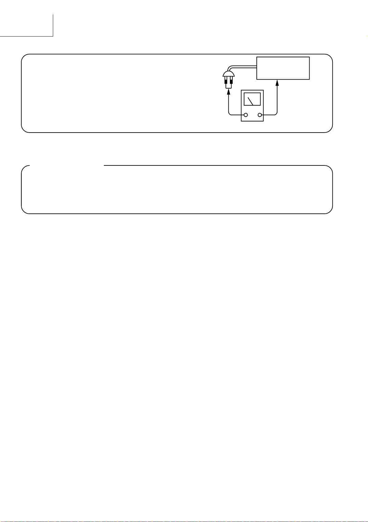
Before any service is performed on the chassis an
isolation transformer should be inserted between the
power line and the product.
1. When replacing the chassis in the cabinet, ensure
all the protective devices are put back in place.
2. When service is required, observe the original
lead dressing. xtra precaution should be taken to
ensure correct lead dressing in any high voltage
circuitry area.
3. Many electrical and mechanical parts in
HITACHI products have special safety related
characteristics. These characteristics are often not
evident from visual inspection, nor can the
protection afforded by them necessarily be
obtained by using replacement components rated
for higher voltage, wattage, etc. Replacement
parts which have these special safety
characteristics are identified by marking with a
on the schematics and the replacement parts
list.
The use of a substitute replacement component
that does not have the same safety characteristics
as the HITACHI recommended replacement one,
shown in the parts list, may create electrical
shock, fire, X-radiation, or other hazards.
4. Always replace original spacers and maintain lead
lengths. Furthermore, where a short circuit has
occurred, replace those components that indicate
evidence of overheating.
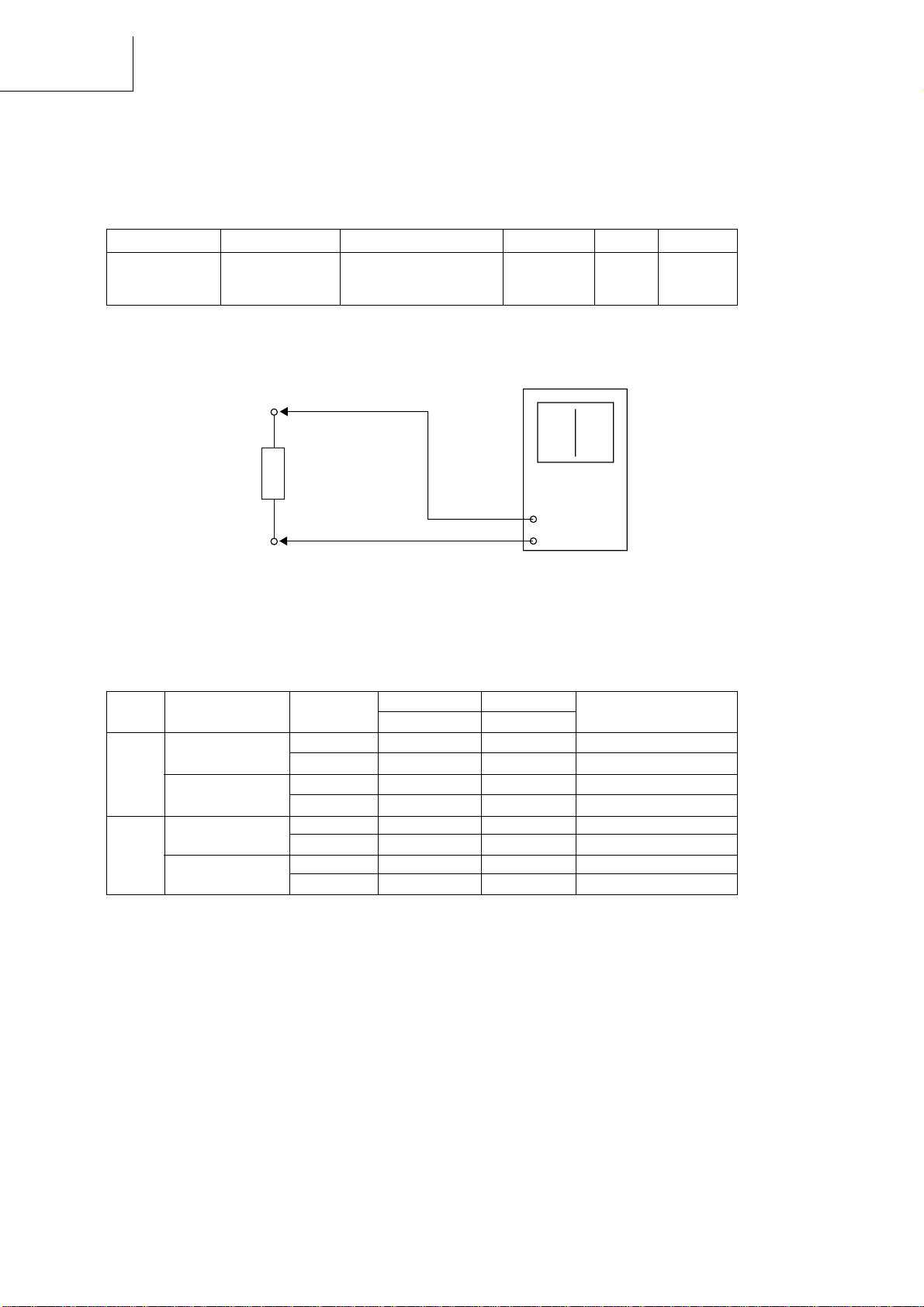
5. Insulation resistance should not be less than 2M
ohms at 500V DC between the main poles and
any accessible metal parts.
6. No flashover or breakdown should occur during
the dielectric strength test, applying 3kV AC or
4.25kV DC for two seconds between the main
poles and accessible metal parts.
7. Before returning a serviced product to the
customer, the service technician must thoroughly
test the unit to be certain that it is completely safe
to operate without danger of electrical shock. The
service technician must make sure that no
protective device built into the instrument by the
manufacturer has become defective, or
inadvertently damaged during servicing.
CE MARK
1. HITACHI products may contain the C mark on
the rating plate indicating that the product
contains parts that have been specifically
approved to provide electromagnetic
compatibility to designated levels.
2. When replacing any part in this product, please
use only the correct part itemised in the parts list
to ensure this standard is maintained, and take
care to replace lead dressing to its original state,
as this can have a bearing on the electromagnetic
radiation/immunity.
PICTURE TUBE
1. The line output stage can develop voltages in
excess of 25kV; if the .H.T. cap is required to be
removed, discharge the anode to chassis via a
high value resistor, prior to its removal from the
picture tube.
2. High voltage should always be kept at the rated
value of the chassis and no higher. Operating at
higher voltages may cause a failure of the picture
tube or high voltage supply, and also, under
certain circumstances could produce X-radiation
levels moderately in excess of design levels. The
high voltage must not, under any circumstances,
exceed 29kV on the chassis (except for projection
Televisions).
3. The primary source of X-radiation in the product
is the picture tube. The picture tube utilised for
the above mentioned function in this chassis is
specially constructed to limit X-radiation. For
continued X-radiation protection, replace tube
with the same type as the original HITACHI
approved type
4. Keep the picture tube away from the body while
handling. Do not install, remove, or handle the
picture tube in any manner unless shatterproof
goggles are worn. People not so equipped should
be kept away while picture tubes are handled
LASERS
If the product contains a laser avoid direct exposure to
the beam when the cover is open or when interlocks are
defeated or have failed.
- 1 -

HTA-DD3
2
Check that exposed parts are acceptably insulated from
the supply circuit before returning the repaired instrument
to the customer.
• Checking method
Measure the resistance value between the both poles of
attachment cup (Power supply plug and the exposed
parts (Parts such as Knob, Cover, etc. where the cus-
tomer is easy to touch. and check that the resistance
value is 500 kohms or more.
INSTRUMENT
(Exposed part)
Insulation tester (DC 500V)
SAFETY PRECAUTIONS
The following precautions should be observed when servicing.
1. Since many parts in the unit have special safety-related characteristics, always use genuine Hitachis replace-
ment parts. Especially critical parts in the power circuit block should not be replaced with other makers. Critical
parts are marked with _ in the circuit diagram and printed wiring board.
2. Before returning a repaired unit to the customer, the service technician must thoroughly test the unit to ascertain
that it is completely safe to operate without danger of electrical shock.

HTA-DD3
3
SPECIFICATIONS
AUDIO SECTION
(Power amplifier) For (E, EBS) For (W, WUN, WAU)
Rated output: Front: 80 W + 80 W (6 Ω/ohms, 20 Hz ~ 20 kHz with 0.1 % T.H.D.) 100 W + 100 W ( IAJ, 6 ohms)
Centre: 80 W (6 Ω/ohms, 20 Hz ~ 20 kHz with 0.1 % T.H.D.) 100 W ( IAJ, 6 ohms)
Surround: 80 W + 80 W (6 Ω/ohms, 20 Hz ~ 20 kHz with 0.1 % T.H.D.) 100 W + 100 W ( IAJ, 6 ohms)
SINUS power: Front: 90 W + 90 W (6 Ω/ohms, 1 kHz, 0.1 %)
Centre: 90 W (6 Ω/ohms, 1 kHz, 0.1 %)
Surround: 90 W + 90 W (6 Ω/ohms, 1 kHz, 0.1 %)
Output terminals: Front: A or B 6 to 16 Ω/ohms
A + B 12 Ω/ohms or more
Center/Surround: 6 to 16 Ω/ohms
(Analog)
LINE input
Input sensitivity / input impedance: 200 mV / 47 kΩ/kohms
Frequency response: 10 Hz ~ 50 kHz: +1, 3 dB
S/N ratio: 93 dB (IHF-A weighted)
Total harmonic distortion: 0.1% (20 Hz ~ 20 kHz)
PHONO input-REC OUT
Input sensitivity / input impedance: 2.5 mV / 47 kΩ/kohms
RIAA deviation: ±1 dB (20 Hz ~ 20 kHz)
S/N ratio: 74 dB (IHF-A weighted, with 5mV input)
Total harmonic distortion: 0.03% (1 kHz, 3V)
Rated output / Maximum output: 150 mV / 7V
•VIDEO SECTION
(Composite)
Input/output level and impedance: 1 Vp-p, 75 Ω/ohms
Frequency response: 5 Hz ~ 10 MHz +1, 3 dB
(S-Video)
Input/output level and impedance: Y=1 Vp-p, C=0.286 Vp-p
Frequency response: 5 Hz ~ 10 MHz +1, 3 dB
(Component)
Input/output level and impedance: Y=1 Vp-p, C
B
=0.7 Vp-p, C
R
=0.7 Vp-p
Frequency response: 5 Hz ~ 10 MHz +1, 3 dB
•TUNER SECTION
[FM] (note: µV at 75Ω/ohms, 0 dBF = 1 ∞ 10
-15
W) [AM]
Receiving range: 87.50 MHz ~ 108.00 MHz (0.05 MHz step) 522 kHz ~ 1611 kHz (9 kHz step) ( , BS)
522 kHz ~ 1611kHz (9 kHz step),
520 ~ 1710 kHz (10 kHz step) (W, WUN,WAU)
Usable sensitivity: 2.0 µV (17.2 dBf) 600 µV
50 dB quieting sensitivity: ST R O 23µV (38.5 dBf)
S/N ratio: MONO 80 dB (IHF-A weighted)
ST R O 75 dB (IHF-A weighted)
Total harmonic distortion: MONO 0.2% (1kHz)
ST R O 0.4% (1kHz)
• GENERAL
Power supply: AC 230V, 50 Hz ( , BS), AC 110 ~ 127V/220 ~ 240V, 50/60 Hz (W, WUN,WAU)
Power consumption: 180 W (Standby mode = 1.5W)
Maximum external dimensions: 434 (W) ∞ 144 (H) ∞ 320 (D) mm
Weight: 8.1 kg
• REMOTE CONTROL UNIT (RB-DD1S)
Batteries: R6P/AA Type (two batteries)
External dimensions: 54 (W) ∞ 172 (H) ∞ 27.2 (D) mm
Weight: 100 g (including batteries)
• Accessory supplied: Operating instructions, Remote control unit (RB-DD1S),
R6P/AA batteries, AM loop antenna and FM indoor antenna
* For purposes of improvement, specifications and design are subject to change without notice.

HTA-DD3
4
1
2
1
Top cover
x 2
x 2
x 4
Rear Plate
3
x 28
4
x 1
21
x 5
Fig.1
Fig.2
SERVICE POINTS
1. Removal of Top Cover
(a Remove 2 screws 1 from each side.
(b Remove 4 screws 2 from the rear plate.
2. Removal of Rear Plate
(a Remove 28 screws 3 and 1 screw 4 from the rear plate.
(b Remove 5 screws - from the Bottom Chassis.

HTA-DD3
5
6
Claws (PWB Support)
5
6
Flat Cable
7
8
x 4
x 1
x 1
20
x 3
x 4
Z
19
E
A
BCD
F
H
IJK
N
L
M
OP Q
Main PWB
DSP PWB
Push Rivet
Holder (Back)
Holder (Front)
Audio PWB
S Video PWB
Composit PWB
Component PWB
Relay PWB
Tuner
PWB
SHIELD
PLATE
DSP PWB
19 x 1
for E, E(BS)
Fig.4
3. Removal of Tuner & DSP PWB board
(a Remove the Push Rivet from the Holder (Front & Holder (Back then remove the flat cable Z at the Tuner PWB.
(b Remove 1 screw + to detech the shield plate from the bottom chassis.
(c Gently pull the Tuner & DSP PWB board upwards to detach its connectors A, B, C, D, E & F from Main
PWB board.
Removal of Audio PWB board
(a Gently pull the Audio PWB board upwards to detach its 4 connectors H, I, J & K from Main PWB board.
Removal of S Video/Composit PWB board
(a Gently pull the Composit and S Video PWB board upwards to detach its 2 connectors L & M from Main PWB
board.
Removal of Components PWB board
(a Gently pull the Components PWB board upwards to detach its connector N from Main PWB board.
Removal of Relay PWB board
(a Gently pull the Relay PWB board upwards to
detach its 3 connectors O, P & Q from
Main PWB board.
4. Removal of Transformer
(a Remove 4 screws 5 from the transformer.
(b Pull the transformer upward together with the Power PWB section.
Removal of Power PWB board
(a Remove 1 screw 6 from the Botton chassis at the side.
(b Release the Power PWB board from its 3 holding claws (PWB support and gently pull the board free.
Removal of Main PWB board
(a Detach Flat Cable from FL PWB Board.
(b Remove 4 screws 7 to release the Power IC from the heat-sink.
(c Remove 3 screws , to release the bracket from the heat-sink.
(d Remove 1 screw 8 to release the Component from the heat-sink.
Removal of Heat-Sink
(a Invert the Botton Chassis, remove 2 screws
9 connect to the heat-sink (Fig 5 .
Fig.3

HTA-DD3
6
12
12
Nut x 1
Inner Panel
Nut x 2
15
13
x 1
x 1
14
x 2
x 2
x 11
9
10 x 4
x 2 11 x 1
Bottom Chassis
Bass/Treble Knob
Master Vol.
Front Panel
Fig.6
5. Removal of Front Panel
(a Invert the Bottom Chassis and remove 4 screws !.
(b Remove the Master Vol. & Bass/Treble knob before remove the Front panel.
6. Removal of Inner Panel, Power Switch, Phone Jack & FL board.
(a Release the inner panel from the bottom chassis by remove 1 screw " (Fig 5 and 2 screws #.
(b Remove 11 screws $ and 3 nuts to release the FL board.
(c Remove 2 screws % to release the Power switch.
(d Remove 2 screws & to release the Phone Jack.
Fig.5

HTA-DD3
7
16 x 4
7. Removal of Foot
(a Remove 4 screws ( to remove foot.
Fig.7

HTA-DD3
8
* R22
DC balance meter
1 FM Discriminator
Measuring instrument and condition.
2 Voltage of covering (Reference
3 Tuning level (dB adjusment
Input FM antenna, 1 KHz, 26 dBµV, 75 KHz
Adjust VR1
Limit 26±2dB
(NOTE Adjust VRI until "Tuned" Indicator light on.
Input terminal Output terminal Measuring instrument Frequency Adjust Reading
FM antenna * R22 DC balance meter 98.1 MHz T4 0±30mV
1kHz, 60dBu,
22.5kHz dev.
Band Destination Frequency Specification Note
Limit(V Average(V
FM E/EBS 87.50MHz 1.3-3.7 2.4
(50kHz step 108.00MHz 6.0-9.0 7.5
W/WUN/WAU 87.50MHz 1.3-3.7 2.4
(50kHz step 108.00MHz 6.0-9.0 7.5
AM E/EBS 522kHz 0.9-1.2 1.1
(9kHz step 1,611kHz 6.0-9.0 7.5
W/WUN/WAU 522kHz 0.9-1.2 1.1
(9kHz step 1,611kHz 6.0-9.0 7.5
ADJUSTMENTS

9
HTA-DD3
WIRING DIAGRAM
FL DISPLAY UNIT CN2B
CN1B
CN1A
CN1BCN2A
W17A
W15A
W16A
W18A
W14A
W19A
W13A
CN204
CN204A
CN201A
CN14
CN12
TUNER/VOL UNIT
AUDIO IN. UNIT DIGITAL IN. UNIT
VIDEO(C)IN. UNIT
VIDEO(S)IN. UNIT
MAIN UNIT
CN22
PG22
PG13
CN205
THERMAL
UNIT
VIDEO(COMP.)IN. UNIT
SPEAKER OUT. UNIT
CN206
PG14
CN201
DSP UNIT
PG205
PG206
W19B
W18B
W17B
W16B
W15B
W14B
W13B
POWER T.(2nd) UNIT
W5B
W7B
W9B
W6B
W8B
W10B
W4B
POWER T.(Pry.) UNIT
POWER CONTROL UNIT
PG3
CN13
CN3
PHONES/SPEAKER SW UNIT
POWER SW UNIT
*PG15
PG12
W3A
W1A
W1B W2B
W6A W7A
W10A W9A W8A
W3B
W2A
POWER CORD
PG25
*VOLTAGE SELECTOR
(for W, WUN, WAU)
REMARKS * SHOULD BE FOLLOW PWB ASS'Y.
*CN15

HTA-DD3
PRINTED WIRING BOARD
- 10 -
Soldering Side
MAIN PWB

HTA-DD3
- 11 -
Component Side
MAIN PWB

HTA-DD3
Soldering Side
Tuner PWB
- 12 -

HTA-DD3
Component Side
Tuner PWB
- 13 -

HTA-DD3
Soldering Side
Component Side
Audio PWB
- 14 -

HTA-DD3
RelayPWB
Soldering Side
Component Side
- 15 -

HTA-DD3
DigitalPWB
Power PWB
Component Side
FL PWB - 16 -

HTA-DD3
Soldering Side
FL PWB
Power PWB
Digital PWB

HTA-DD3
Component Side
Soldering Side
Component PWB

HTA-DD3
Component Side
Soldering Side
DSP PWB
This manual suits for next models
5
Table of contents
Other Hitachi Speakers manuals

Hitachi
Hitachi BTN5 User manual

Hitachi
Hitachi BTN2 User manual

Hitachi
Hitachi HSHS501WE User manual

Hitachi
Hitachi AXS014BTU User manual

Hitachi
Hitachi HS-371 User manual

Hitachi
Hitachi W50 User manual

Hitachi
Hitachi W50 User manual

Hitachi
Hitachi HS-630 User manual

Hitachi
Hitachi AXS030BTU User manual

Hitachi
Hitachi AXS460BTU User manual