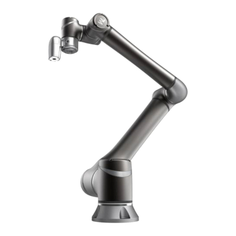
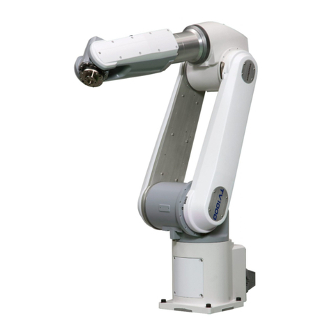
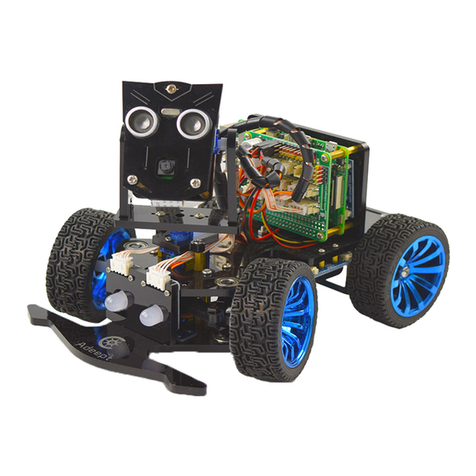
Hitbot Z-Arm 2140 User manual

Huiling-tech Robotic Co., Ltd
Z-Arm 2140 APP Software
Instructions

HITBOT Z-Arm 2140
E-Mail: hitbot@hitbot.cc
APP Software Instructions of Z-Arm 2140
Before you start, you need to know the basic information below:
When it is controlled by the mobile terminal, the range of motion of each joint is defined as
follows:
Z axis (axis 3): [-210/-310mm, 0], the highest point is 0, and downward is negative;
Big arm (axis 1): [-90 degrees, 90 degrees], the front of the robot arm is 0°, and clockwise is
negative, counterclockwise is positive;
Small arm (axis 2): [-180 degrees, 180 degrees], the big arm along the direction away from the
machine is 0°, and clockwise is negative, counterclockwise is positive.
The end (axis 4): [-180, 180], the front of the machine is 0°, and clockwise is negative,
counterclockwise is positive.
Note: At some special positions, the range of motion may be less than the above instructions.
For example, when the big arm is at 90°the small arm cannot reach 180°when it moves
anticlockwise, because it will collide with the machine.
Huiling-tech Robotic Co., Ltd

HITBOT Z-Arm 2140
E-Mail: hitbot@hitbot.cc
Huiling-tech Robotic Co., Ltd
1. Add equipment
Download the "HITBOT" APP, and open the position service in the settings;otherwise,
the APP cannot search robotic arm signals; for the system of Android 6.0 above, when you
open HITBOT for the first time, it will apply to the relevant authority; in order to guarantee the
normal work of the APP, please allow execution of operations. After the robotic arm is
energized, click on the "+" button (Figure 1) to add the robotic arm equipment. As shown in
Figure 2, click OK, and it will automatically jump to the interface shown in Figure 1.
Figure 1 Figure 2
2. Application of system functions
Turn on the switch shown in Figure 3. When "Connected" is displayed, click on the equipment and it
will jump to Figure 4. We can see that there are four functions, i.e. 3D graphical teaching, drag teaching
(not supported currently), icon sketching and freehand sketching; click on the icon on the right side of the
"+" button at the upper right corner, and you can set wireless, wired and speed torque by following the
prompts.

HITBOT Z-Arm 2140
E-Mail: hitbot@hitbot.cc
Huiling-tech Robotic Co., Ltd
Figure 3 Figure 4
2.1 3D graphical teaching
Click on the 3D graphical teaching; if this is the first connection, it will automatically
initialize the robotic arm speed and torque related settings; when it prompts to set
successfully, you need to click on the 3D graphical teaching again, and the system will initialize
the function module. After initialization, we can rotate the 3D image of the robot arm at 360
degrees on the mobile phone to adjust the viewing angle (as shown in Figures 5 and 6).
Figure 5 Figure 6

HITBOT Z-Arm 2140
E-Mail: hitbot@hitbot.cc
Huiling-tech Robotic Co., Ltd
In this function, we can double click on the big arm, small arm positions to slide left and
right (as shown in figures 7 and 8) or double click on the Z axis position to slide up and down
(as shown in Figure 9), and the control mode of joint 4 is similar to other joints, to control the
robotic arm. At this time, the robotic arm will move according to the trajectory you are moving
on your mobile phone. Double click black background to exit control.
Figure 7 Figure 8 Figure 9
When the robotic arm moves to a certain position according to the track that you make
on your mobile phone, we can click the ADD-HEAD or ADD-TIAL button to add the position,
and click CTRL to open the control menu to view the added positions information (as shown
in Figure 10).
Figure 10 Figure 11

HITBOT Z-Arm 2140
E-Mail: hitbot@hitbot.cc
Huiling-tech Robotic Co., Ltd
By doing so, after adding two or more position coordinates, you can click on CTRL to pop
up control menu; click RUN button, it will pop up the cycle number setting interface after
jumping (as shown in Figure 11); after setting, click RUN button, the robotic arm will move
according to the movement track and settings we added before.
2.2 Drag teaching (not supported currently)
After clicking drag teaching, the system will initialize automatically. After initialization,
click the robotic arm icon below the software, and enter the interface shown in Figure 12.
Click the "drag mode", you need to wait for the setting successfully, then you can use an
external force to drag big arm and small arm positions; if you need to change the Z axis
position, you need to double click Z axis joint on the mobile phone to select, and slide up and
down on the screen, to make the robot arm Z axis joint to move. When we drag the robot
arm to a certain position, we can click the Add button to add the coordinates of this position.
By doing so, after adding two or more position coordinates, click the motion mode button,
and the big arm and small arm will return to zero position; you can, click the run button only
after setting successfully, to pop up the cycle number interface (as shown in Figure 13); after
setting, the robotic arm will move according to the movement track and settings we added
before.
Figure 12 Figure 13

HITBOT Z-Arm 2140
E-Mail: hitbot@hitbot.cc
Huiling-tech Robotic Co., Ltd
2.3 Image sketching
Recognition principle: firstly, it will transform the image into a grayscale image, and then
recognize each connected area and extracted the contour.
After entering the icon sketching module, click on the toolbox at the lower left corner,
and we can make a series of operations (as shown in Figure 14).
When we take pictures directly or import pictures from the gallery, the system will
automatically process the image, and then we will adjust the image according to three
dragging bars on the left side of the screen (resolution, fine tuning 1, fine tuning 2) (as shown
in Figure 15). After adjustment, click the "Print" button, the robotic arm will "draw" according
to the image.
Figure 14 Figure 15
Note:
1. The contrast of the colors in the selected image should be bigger, convenient for the system
to process.
2. The significance of the three vertical dragging bars shown in Figure 14:
The first dragging bar (resolution): This value is used to adjust the image to grayscale, and
adjust the total effect map after recognition;
The second dragging bar (fine tuning 1): Remove connected areas with component points
less than this value.
The third dragging bar (fine tuning 2): Remove connected areas with component points more
than this value.

HITBOT Z-Arm 2140
E-Mail: hitbot@hitbot.cc
2.4 Freehand sketching
We can directly write the text or pattern on the drawing board (as shown in Figure 16),
and then click the send button, then the robotic arm will work according to the patterns we
draw. We can also check the "Auto" button at the lower left corner, and then if we draw a line
on the drawing board, the robot arm will also follow a line, so repeatedly, we will get the
pattern we want.
Figure 16
Huiling-tech Robotic Co., Ltd

Huiling-tech Robotic Co., Ltd
Tel
Email
Website
Address
0755-36382405
www.z-arm.com
1st floor, 3 Building, Robot Intelligence and Manufacturing Industrial Park,
Dayang Road90, Baoan District, Shenzhen, Guangdong, PR China.
