Page 4
Prime and Calibrate should be done at the pump.
Cut off metal straps and unscrew the lid.
With the pump power on and the installation section complete the output hose should be in the
top of the Tote with the ball valve or at least the mating quick disconnect, connected.
Controller Calibration
The Touch Screen ------ all highlighted items are buttons on the touch screen
Press Settings, Calibration
Press PID ON --- This will change to PID OFF
Press to the right of VFD% and type in 100 and Press enter
Press Back
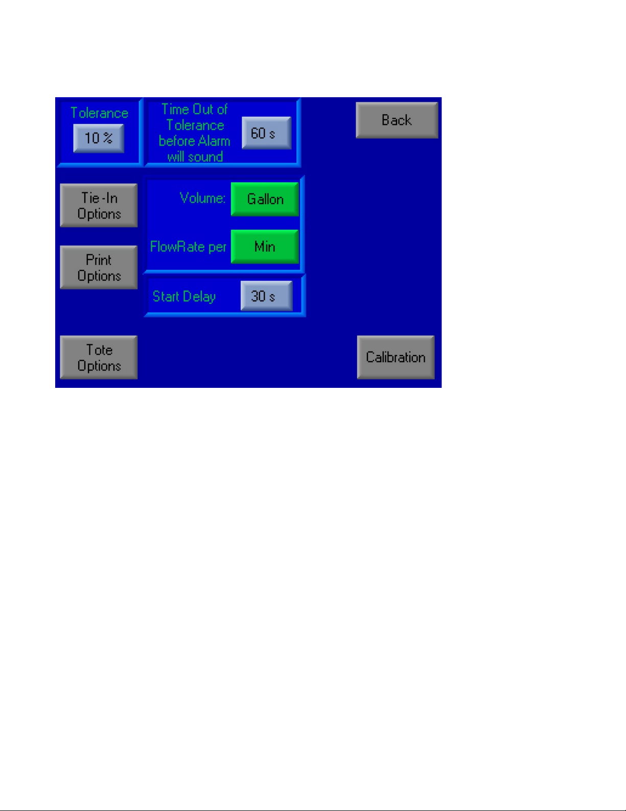
Set Start Delay to 0
Set Time out of Tolerance to 0
Press Back
Set all options to a typical plant run. Ideally Target Flow Rate should be greater than 0.04
Press Start
Flow should begin shortly. Do not run for more than 3 min.
Once Steady flow is achieved
Press Stop ----- same location as start
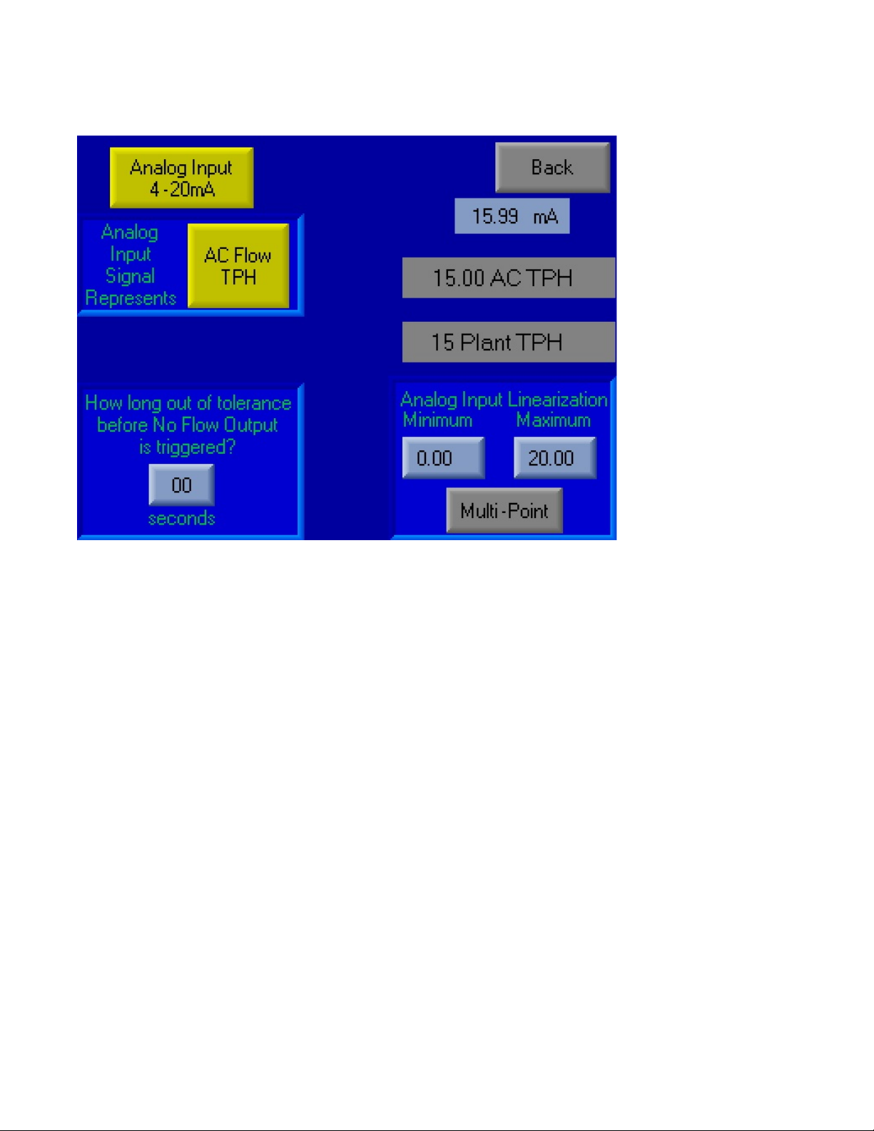
Press Settings, Calibration
Press to the right of VFD% and type in 50 and Press enter
Press PID OFF --- This will change to PID ON
Press Auto Tune? --- This will change to Auto Tune On Next Run
Press Back, Back, Start
The frequency drive will go from 0 to 60 several times.
Once the Flow rate stabilizes (Less than 5 min on average) the Pump can be stopped and connected
as a typical run would be. Close the Tote lid and place Ball Valve onto the Injection site.