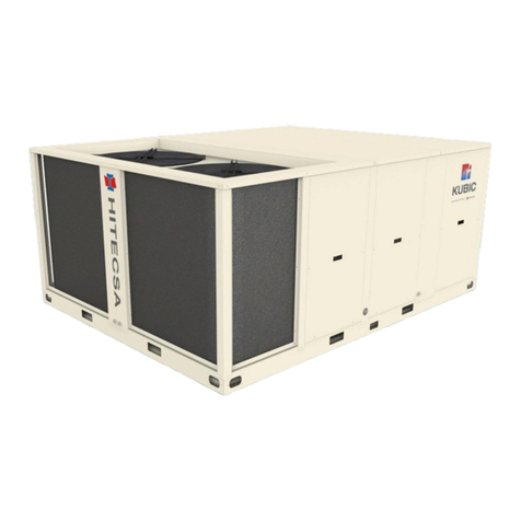
Hitecsa WPVBZ HE Instruction manual

1
IOM_WPVBZ HE-WPVZ HE_401-1201-4002_208110_200901_EN
PACKAGED COMPACT VERTICAL –WATER / AIR
WPVBZ HE / WPVZ HE
WPVBZ HE WPVZ HE
Heat pump Cooling only
PACKAGED COMPACT VERTICAL WATER-AIR UNITS
INSTALLATION, OPERATION & MAINTENANCE MANUAL
IOM_WPVBZ HE-WPVZ HE_401-1201-4002_208110_200901_ES
Models: 401 - 1201 - 4002

2
IOM_WPVBZ HE-WPVZ HE_401-1201-4002_208110_200901_EN
PACKAGED COMPACT VERTICAL –WATER / AIR
WPVBZ HE / WPVZ HE
Thank you for trusting the Hitecsa Products. Our company has been offering the market an extended range of specialized units for air
conditioning and cooling installations for over 35 years. Our approach is based on efficiency, flexibility and on practical solutions. This has
been the hallmark of our product catalogue.
The versatility of our factory allows us to deliver solutions that can meet any requirement and we endeavour solving any problem that may
arise in designing and implementing air conditioning installations.
From all of us at Hiplus Aire Acondicionado, once again, thank you very much.

3
IOM_WPVBZ HE-WPVZ HE_401-1201-4002_208110_200901_EN
PACKAGED COMPACT VERTICAL –WATER / AIR
WPVBZ HE / WPVZ HE
INDEX
INTRODUCTION ............................................................................................................................4
REGULATIONS AND CERTIFICATIONS.......................................................................................5
SAFETY PRECAUTIONS...............................................................................................................6
TECHNICAL SPECIFICATIONS ....................................................................................................8
TRANSPORT ...............................................................................................................................10
INSPECTION AT RECEPTION .......................................................................................................................................... 10
RIGGING ........................................................................................................................................................................ 10
STORAGE ....................................................................................................................................................................... 10
INSTALLATION............................................................................................................................11
SERVICE AREA (MM)........................................................................................................................................................ 11
WEIGHT DISTRIBUTION (KG)........................................................................................................................................... 11
DIMENSIONS.................................................................................................................................................................. 12
INSTALLATION SITE ........................................................................................................................................................ 14
UNIT SETTLEMENT ......................................................................................................................................................... 14
DRAIN ............................................................................................................................................................................ 14
ELECTRICAL INSTALLATION ............................................................................................................................................ 14
WATER INSTALLATION ................................................................................................................................................... 15
Water filling................................................................................................................................................................ 15
Purging ....................................................................................................................................................................... 15
Risk of frost................................................................................................................................................................. 15
Glycol additions .......................................................................................................................................................... 15
HYDRAULIC CIRCUIT AND ITS COMPONENTS................................................................................................................. 16
Regulating devices...................................................................................................................................................... 17
Condenser water regulating valve.............................................................................................................................. 17
HYDRAULIC DIAGRAM ................................................................................................................................................... 18
HYDRAULIC CONNECTIONS WITH WATER PRESSURE REGULATING VALVE (OPTION) ................................................... 19
ELECTRICAL CONNECTIONS ........................................................................................................................................... 20
Connection of thermostats ......................................................................................................................................... 20
Electrical connection of the hydraulic devices with TH-TUNE and µPC ...................................................................... 21
OPERATION ................................................................................................................................22
BEFORE START-UP.......................................................................................................................................................... 22
START UP ....................................................................................................................................................................... 22
OPERATION LIMITS ........................................................................................................................................................ 23
EC MOTOR FAN .............................................................................................................................................................. 24
Safety instructions ...................................................................................................................................................... 24
Working on the device................................................................................................................................................ 25
Modifications / interventions in the device ................................................................................................................ 26
TH TUNE CONTROLLER................................................................................................................................................... 27
Start / Stop ................................................................................................................................................................. 27
Setpoint Temperature Adjustment ............................................................................................................................. 27
Operation modes ........................................................................................................................................................ 27
Indoor Fan: ................................................................................................................................................................. 27
WARNINGS ....................................................................................................................................................................... 27
Description of the warding codes ............................................................................................................................... 27
Alarms ........................................................................................................................................................................ 27
DESCRIPTION OF THE ALARM CODES............................................................................................................................. 28
MAINTENANCE ...........................................................................................................................29
EC MOTOR FANS ............................................................................................................................................................ 30
Rotation caused by an air flow in false direction........................................................................................................ 30
Diagnosis / Faults ....................................................................................................................................................... 31
Status Out with flash code.......................................................................................................................................... 32
REFRIGERANT CHARGE .................................................................................................................................................. 34

4
IOM_WPVBZ HE-WPVZ HE_401-1201-4002_208110_200901_EN
PACKAGED COMPACT VERTICAL –WATER / AIR
WPVBZ HE / WPVZ HE
INTRODUCTION
Purpose of this Manual
This manual and any other instructive document attached as refrigeration lines design, electrical
diagrams, etc. have been written to allow a correct installation, commissioning and maintenance of
the unit. Therefore it is essential to read the instructions with due attention.
Verify that all the necessary information for the correct installation of the system is included in the
manuals supplied with this unit and/or the rest of the indoor units, accessories, etc. Otherwise, the
manufacturer declines any responsibility for any damage to persons, animals or things, as a result of
improper use of the unit and/or failure to observe these instructions.
In case of different interpretations and/or errors the documentary priority will be: 1. Characteristics
plate of the unit, 2. IOM (this document), 3. EDM, technical catalogue, 4. UM user manuals.
Conservation of the Manual
This manual and the electric diagram of the unit must be retained and remain available to the operator for any further
consultation.
Updating the Data
The continuous improvement in design and performance to which we are committed gives us the right to modify the
specifications of our products without prior notice.
Electrical Supply
Check that the electrical network features are in accordance to data shown in the data nameplate of the
unit.
Local Safety Regulations
Observe and analyse all possible causes of accidents that may arise in the place or places of installation of the units, check
means and tools to use, etc. It is not possible to anticipate each and every one of the potential circumstances of danger in
this manual. Respect the valid local security standards during installation.
Principles of Security on Installation
The unit is designed and built in a way that does not pose a risk to the health and safety of people. Appropriate solutions
for the project have been adopted to eliminate the possible causes of risk in the installation.
Packaging and Replacement of Equipment
The material of the package (plastic bags, insulating materials, nails, etc.) is a potential source of danger.
Consequently, it should be kept out of the reach of children and properly recycled according to the valid
local safety regulations.
This product should not be mixed with household waste at the end of its life. Due to the refrigerant, oil and
other components contained in this product, it must be dismantled by professional installers, all waste
should be sent, according to its nature to recycling, composting or treatment plants, or to an authorized
waste management agency in accordance with the current local legislations.
Utilization
The unit will only be used for the purpose it has been designed. Any other use does not imply any kind of liability or
responsibility from the manufacturer.
Incorrect Operation
In case of breakdown or operation faults, turn the unit off.

5
IOM_WPVBZ HE-WPVZ HE_401-1201-4002_208110_200901_EN
PACKAGED COMPACT VERTICAL –WATER / AIR
WPVBZ HE / WPVZ HE
INTRODUCTION
Periodic Inspections and Maintenance
Carry out periodic inspections to detect possible damaged or broken parts. If these parts are not repaired
it could cause damage to people or material. Before executing any maintenance operation, switch the unit
power supply off.
Make sure to keep the maintenance areas open. If these areas have to be invaded by the construction of
air supply and/or lateral return ducts, verify that the design of the ducts allows the access to the fans and
the replacement of the filters.
All operations shall be carried out in accordance with the local safety regulations.
Repairing Operations
The reparations shall always and exclusively be completed by trained personal authorized by the
manufacturer using original spares. The safety devices of the unit could be affected due to the failure to
comply with these warnings.
Modifications
The manufacturer will not respond to the warranty and to the possible damages of the unit in case of electrical and/or
mechanical modifications. The unauthorized manipulation, reparation or modification of the unit will automatically invalidate
the warranty.
Refrigerant
This product is hermetically sealed and contains R-407C which is a HFC fluorinated greenhouse gas.
REGULATIONS AND CERTIFICATIONS
ISO 9001 CERTIFICATION: HIPLUS AIRE ACONDICIONADO S.L., by endeavouring to always gain the maximum
satisfaction from their customers, obtained the ISO 9001: Quality System for its design and production activities. That result
shows our continuous determination to improve quality and the reliability of all our products. Our commercial activities,
design, raw materials, production processes and after-sales service represent the means to reach our goal.
CE MARKING: Our products are CE marked according to the essential requirements of the applicable EC directives and
their last modifications and comply with the national legislation of each country.

6
IOM_WPVBZ HE-WPVZ HE_401-1201-4002_208110_200901_EN
PACKAGED COMPACT VERTICAL –WATER / AIR
WPVBZ HE / WPVZ HE
SAFETY PRECAUTIONS
Before starting any installation, service or maintenance operation, turn off the main power switch in
order to avoid electrical shock that may cause personal damages.
In case of folding electrical panels, before folding them up in order to access to the interior of the machine, it is
MANDATORY to disconnect the power supply hose from the electrical voltage, THE LINE MUST ALWAYS BE
FREE OF VOLTAGE for this operation.
It is absolutely prohibited to realize any operation on parts that are electrically powered on. The protection class
of the opened equipment is IP00!
The absence of voltage must be confirmed by a minimum two poles voltage tester.
DANGER
Do not touch or adjust the safety devices inside any unit of the system. For repairs use only original spare parts
and mount them properly in the same position where old parts were placed.
The installation and maintenance of air conditioning equipment may be dangerous because the system is under
pressure, some of its elements have high temperatures and include electrical components.
Do not install the unit in an explosive atmosphere.
The units equipped with water-air, water-water, or refrigerant-water heat exchangers shall be protected
properly against damage caused by frost. A proper protection is obtained by adding the necessary anti-
frost liquid so that the freezing temperature becomes minimum -2°C (6% when using Ethylene Glycol).
Moreover when the ambient temperature in any part of the installation may reach values lower than 5°C
it is COMPULSORY to protect the unit and the whole installation with additional measures such as
heating tubes, draining the unit and the whole installation for water (when the unit is not under
operation) or adding more anti-frost liquid so that the freezing point always will be lower than the
minimum temperature that the ambient air may reach.
Even after disconnecting the main voltage, life-threatening charges may appear between the protective ground
“PE” and the main connection.
When the motor runs independently due to air flowing through or if it continues to run down after being turned off,
dangerous voltages of over 50 V can arise on the internal connections of the motor through operation of the
generator.
When there are EC motors or motors with variable speed control, the protective earth is conducting high discharge
currents (depending on the switching frequency, current source voltage and motor capacity). Grounding in
compliance with EN specifications shall therefore be observe even for testing and trial conditions (EN 50 178, Art.
5.2.11). Without grounding, dangerous voltages can be present on the motor housing.
Because of the use of capacitors, danger of death exists even after switching off the device in case of direct
contact with conductive parts or with parts that carry voltage due to fault condition. It is only allowed remove or
open the housing of the controller when the power supply cable is disconnected and after a waiting time of 3
minutes.
The warranty of the unit will not respond to the damages caused by frozen water.
WARNING!

7
IOM_WPVBZ HE-WPVZ HE_401-1201-4002_208110_200901_EN
PACKAGED COMPACT VERTICAL –WATER / AIR
WPVBZ HE / WPVZ HE
SAFETY PRECAUTIONS
Only qualified and trained service staff (technical service) must make the installation, commissioning and carry
out maintenance works. Unqualified personnel can only make basic tasks such as cleaning and replacement of
filters, etc.
Prevent access to children so they cannot play with the appliances.
In every visit, all precautions must be taken into account: those recommended in the installation, operation and
maintenance instructions, as well as the ones indicated in labels of the unit. Do not forget to strictly follow any
other safety precautions.
DO NOT introduce objects into the air inlets or outlets that can be drawn into the fan, people, etc.
Use safety glasses, work gloves and any other safety accessory necessary.
The fan / motor may switch on and off automatically for functional reasons.
After power failure or main disconnection automatic restart of the fan may occur when power supplyis back!
Wait for the fan to come to a complete standstill before approaching it!
In the AC external rotor motor the external rotor turns during operation!
For brazing operations use a quenching cloth and take precautions to have at close distance a fire extinguisher.
This product contains fluorinated greenhouse gases, leakage can cause displacement of air and entail insufficient
oxygen to breath.
The decomposition of fluorinated gases when being burned due to e.g. brazing operations, may cause the
existence of highly toxic and corrosive gases.
Must follow all safety recommendations.
ATTENTION!
The responsibility of all personal and material damages caused by an unplanned or inappropriate use will be given
to the person or operating company of the unit, and not to the manufacturer.
WARNING!

8
IOM_WPVBZ HE-WPVZ HE_401-1201-4002_208110_200901_EN
PACKAGED COMPACT VERTICAL –WATER / AIR
WPVBZ HE / WPVZ HE
TECHNICAL SPECIFICATIONS
WPVZ HE / WPVBZ HE
401
1201
4002
REFRIGERANT
Type
-
R407c
GWP (1)
-
1774
Refrigerant charge WPVZ
kg
1.05
3.7
5.8 + 5.8
Refrigerant charge WPVBZ
kg
2
7
9 + 9
COOLING CAPACITIES
Cooling capacity (2)
kW
13.2
41.0
129.3
Total absorbed power (2)
kW
4.33
13.68
44.28
EER coefficient (2)
kW / kW
3.05
3.00
2.92
ηs,c (2)
%
106.8
108.0
103.7
Water flow
mᶟ/h
2.97
9.27
29.4
WPVBZ HE (Heat pump units)
HEATING CAPACITIES
Nominal heating capacity (3)
kW
15.8
49.6
155
Heating capacity (4)
kW
12.7
39.92
124.99
Total absorbed power (4)
kW
3.75
11.67
37.88
COP coefficient (4)
kW / kW
3.39
3.42
3.3
ηs,h (4)
%
109.6
110.7
106.5
Water flow
mᶟ/h
2.6
8.19
25.27
1) GWP: Global Warming Potential (climatic) of 1 kg of greenhouse gas relative to 1 kg of CO2, calculated in terms of 100-year warming
potential.
2) Cooling tower conditions: Room temperature 27/19ºC. Condenser water: inlet 30 ºC / outlet 35ºC.
3) Dry air temperature 20°C. Humid temperature, room air 14°C. Inlet water temperature 16°C.
4) Ground water conditions: Room temperature 20ºC. Evaporator water: inlet 10ºC, Unit’s water flow 100 % inlet 7ºC.

9
IOM_WPVBZ HE-WPVZ HE_401-1201-4002_208110_200901_EN
PACKAGED COMPACT VERTICAL –WATER / AIR
WPVBZ HE / WPVZ HE
TECHNICAL SPECIFICATIONS
WPVZ HE / WPVBZ HE
401
1201
4002
COMPRESSOR
Type
-
Scroll
Quantity
-
1
2
Power supply
V / ~ / Hz
400V / 3 ~ / 50 Hz
Oil type
-
FV68S
160PZ
160SZ
Oil quantity - compressor
L
1.7
3.9
2 x 6.8
INDOOR FAN
Type
-
Radial with EC motor (Plug-Fan type)
Quantity
-
1
2
2
Size
mm
310
400
500
Nominal air flow
mᶟ/h
2400
8200
21500
Nominal available pressure
Pa
50
75
150
Maximum available pressure
Pa
900
940
440
Nominal power - motor
kW
1.4
2.4
3.5
Maximum speed
rpm
2920
2400
1860
Power supply
V / ~ / Hz
230V / 1 ~ / 50 Hz
400V / 3 ~ / 50 Hz
INDOOR EXCHANGER
Type
-
Coil of finned copper tubes
Front surface
m²
0.31
0.84
2.1
Number of stages
-
4
4
4
OUTDOOR EXCHANGER
Type
-
Welded plates
Quantity
-
1
1
2
Water connections (MTP)
ø (")
1
1 1/2
2
Number of plates
-
20
40
70
ELECTRICAL GENERAL SPECIFICATIONS
Power supply
V / ~ / Hz
400V/ 3 ~+ N /50 Hz
Maximum operation current
A
8.7
26.2
87.3
Start-up current
A
54
146
215
DIMENSIONS AND WEIGHT
Length
mm
780
1790
2404
Width
mm
650
870
1157
Height
mm
1380
1630
2122
Duct
mm x mm
297 x 338
373 x 1003
481 x 1407
Weight
kg
165
515
1060
SOUND LEVEL
Total sound power
dB (A)
69
81
91

10
IOM_WPVBZ HE-WPVZ HE_401-1201-4002_208110_200901_EN
PACKAGED COMPACT VERTICAL –WATER / AIR
WPVBZ HE / WPVZ HE
TRANSPORT
INSPECTION AT RECEPTION
It is advisable to check the equipment carefully upon reception.
Check that the equipment has not been damaged during transport and has been supplied complete with all parts
specified in the order and/or with the optional specified in the order. If this is not the case contact the transport
company immediately (within 48h)
Verify the correct voltage of the nameplate and make sure it is in accordance with the local power supply.
In case of any flaw or anomaly detected, please contact HITECSA.
RIGGING
Before moving the unit make sure that all the panels are fixed correctly.
Raise and set down the equipment carefully.
Do not tilt the unit more than 15 degrees during transportation, (Pict. 2).
Always transport the unit in its original packaging to the place of installation.
All units come with a particular rigging diagram of that model similar to the one shown below. Be sure to hoist the
machine through the points indicated in the diagram.
Make sure that the unit is balanced, stable and without any deformations when it is lifted.
STORAGE
If the equipment is going to be stored before the installation, please follow the instructions below in order to avoid damages,
corrosion or deterioration:
Move it carefully.
Do not place the machine in places exposed to ambient temperatures above 50ºC and preferably keep the unit away
from direct sunlight.
Avoid placing the unit with plastic wrapping protection under the sun as the pressure of the circuits could assume
values that could lead to the intervention of the safety valves.
In addition, when cooling, water condensation occurs inside the machine and the plastic wrap.
Avoid placing other objects on top of the unit (unless it is done within the limits of the overlap planes indicated on the
packaging, etc. Follow these indications).
Avoid prolonged storage before installation, water penetration, dust and objects in general due to invasion or
biological, meteorological and/or human impacts.
Minimum storage temperature: 5ºC.
Maximum relative humidity: 90%.
The warranty will not cover any damage caused by frozen water.
WARNING
Fig. 1
Fig. 2

11
IOM_WPVBZ HE-WPVZ HE_401-1201-4002_208110_200901_EN
PACKAGED COMPACT VERTICAL –WATER / AIR
WPVBZ HE / WPVZ HE
INSTALLATION
SERVICE AREA (mm)
Make sure you respect the following measurements for the correct operation of the unit.
WEIGHT DISTRIBUTION (kg)
MODEL
1
2
3
4
Total
401
41
41
41
42
165
1201
128
128
129
130
515
4002
262
262
268
268
1060
(3 –4): Electrical box side

12
IOM_WPVBZ HE-WPVZ HE_401-1201-4002_208110_200901_EN
PACKAGED COMPACT VERTICAL –WATER / AIR
WPVBZ HE / WPVZ HE
INSTALLATION
DIMENSIONS
Model 401
Model 1201
Legend:
1. Water outlet
2. Water inlet
3. 3/4” MPT drain
4. Electrical connections
5.
Connection for pressure operated water valve
Legend:
1. Water outlet
2. Water inlet
3. 3/4” MPT drain
4. Electrical connections
5. Connection for pressure operated water valve
6. Main switch

13
IOM_WPVBZ HE-WPVZ HE_401-1201-4002_208110_200901_EN
PACKAGED COMPACT VERTICAL –WATER / AIR
WPVBZ HE / WPVZ HE
INSTALLATION
DIMENSIONS
Model 4002
Legend:
1. Water outlet
2. Water inlet
3. 3/4” MPT drain
4. Electrical connections
5. Pressure operated water valve connection
6. Main switch

14
IOM_WPVBZ HE-WPVZ HE_401-1201-4002_208110_200901_EN
PACKAGED COMPACT VERTICAL –WATER / AIR
WPVBZ HE / WPVZ HE
INSTALLATION
INSTALLATION SITE
Consult and respect the rules and local regulations which regulate the installation of air conditioning systems.
Choose a site without dust and debris.
Respect the appropriate service area for the equipment that is to be installed.
Verify that the ground or structure on which the unit will be installed is able to support its weight in operation.
Fit shock absorbers throughout the installation to prevent the transmission of noise and vibration.
Check that the direction of the sound level is not going to disturb anyone.
UNIT SETTLEMENT
Make sure that the equipment is levelled correctly.
The bed frame shall be strong enough to support the unit weight.
Verify that the drains are working properly.
Use shock-absorbers for installation.
The manufacturer’s warranty will not cover any refrigerant leakage caused by deterioration due to vibrations if the
shock-absorbers have not been installed correctly between the floor/base stand and the unit.
DRAIN
All the drains are provided with a 3/4” male gas connection (MPT).
The diameter of the condensate drain pipe shall be equal or larger than the unit connection depending on the line
length and the building configuration.
The drainage line shall have a slope of not less than 2% to guarantee thecorrect evacuation of the condensate water.
When the drain line is exposed to air temperatures below 0 degrees, thermal insulation or electrical heating wires
shall be used to prevent the water from freezing and avoid the possible following tube damages.
Install a siphon with the appropriate dimensions (refer to drawing).
ELECTRICAL INSTALLATION
The unit power supply shall be within the 10% of voltage value indicated on the unit nameplate. The Hitecsa warranty
will not cover any damage caused by the start-up of the unit with an incorrect voltage.
Always refer to the unit wiring diagram when completing electrical connections.
The electrical wiring connections and the line protection devices must be installed by the installer according to the
current local laws.
The interconnecting wires shall be protected by a tube or an electrical cable conduit, cable tray, etc.
Turn the main power switch off before starting any type of operation.
WARNING!
Recommended dimensions

15
IOM_WPVBZ HE-WPVZ HE_401-1201-4002_208110_200901_EN
PACKAGED COMPACT VERTICAL –WATER / AIR
WPVBZ HE / WPVZ HE
INSTALLATION
WATER INSTALLATION
The selection and installation of the components of the installation must be carried out by a qualified installer, respecting
the current legislation at the place of work and rules of good practice.
Make sure that you are aware of all the local rules and regulations for hydraulic installations and that you comply with
them.
The design and calculation of pipes shall be carried out in such a way that the pressure drop of the installation never
exceeds that which can overcome the pump built into the unit. In addition, a poor design of the pressure drop of the
branch pipes that go to the indoor units can cause the malfunction of some of them.
Proceed to the installation of a water filter that is provided with an inner net to retain the particles with a maximum
diameter of 0.5 mm.
A proper maintenance of the filter and the flow switch at an appropriate periodicity shall be completed to avoid deposits
that could block them.
Comply with the stated indications regarding the water inlet and outlet of the unit and install a by-pass valve if necessary.
Water filling
Use water at around 20ºC to fill the hydraulic circuit. After the system has been drained, the pressure level must be as
stated in the installation projector according to the pressure level of the main installation. In case when the water installation
of the unit is going to be added to an existing water installation, the main installation probably will comprise a filling system
already.
Attention: An expansion tank with a bigger capacity will be required according to the filled water volume.
Purging
Verify that all the high points of the installation are provided with a bleed valve.
Operate the pump during one minute and stop it. Wait for one minute more and repeat the same process until there is no
more air in the system. 5 to 10 operations may be necessary.
Remember to drain any other components that include tubes where there might be air pockets (example: differential
switch). They will not work properly with air.
Air in the circuit will produce noises, will entail a lower water flow and a bad performance of the exchanger, etc…
Risk of frost
If the unit or the water installation are exposed to temperatures below 5°C it is necessary to take the appropriate measures
against the risk of frost (Please refer to the Safety Precautions section).
For example:
Mix the water of the installation with glycol.
Protect the pipes with heating cables placed under the insulation lining.
Empty the installation and control at the same time that there are no:
- Closed valves that may retain water even after draining the installation.
- Low spots where water may stagnate even after draining; if necessary proceed to blowing the installation.
Glycol additions
Keep in mind that the use of glycol solutions increases the pressure drop.
Make sure that the type of glycol you will use is compatible with hydraulic circuit components (pumps, filters, etc.) and that
it is a non-corrosive product.
GLYCOL ADDITION to WATER (%)
TARGET FREEZING TEMPERATURE
0ºC
-2ºC
-5ºC
-10ºC
-15ºC
-20ºC
-25ºC
-30ºC
ETHYLENE GLYCOL
0%
6%
14%
24%
31%
36%
41%
45%
PROPYLENE GLYCOL
0%
7%
15%
25%
33%
39%
44%
48%
Make sure that the freezing temperature is lower than the minimum temperature that the water may reach keeping a
security margin even when the unit is Off.

16
IOM_WPVBZ HE-WPVZ HE_401-1201-4002_208110_200901_EN
PACKAGED COMPACT VERTICAL –WATER / AIR
WPVBZ HE / WPVZ HE
INSTALLATION
HYDRAULIC CIRCUIT AND ITS COMPONENTS
The most delicatecomponent of the hydraulic circuit isthe plate exchanger. Therefore itis important thatthe units equipped
with plate exchangers operate in an open hydraulic circuit or a thermal loop within the control values as stated in the below
chart. If the Langelier rate is exceeded (lower or higher), the water may become corrosive or incrusting which would
jeopardise the equipment and thus cancel the warranty. In that case it is necessary to use a special exchanger specially
designed for the available water quality.
The units that are equipped with a plate exchanger can operate in an open hydraulic circuit or in a thermal loop provided
that the water quality matches the control values of the following chart.
Contents in water
Concentration mg/l
If higher values
If lower values
Suspended solids
Variable
Possible erosion of the material
No detection of effects
Conductivity
≤ 500 µs/cm
No detection of effects
-
> 500 µs/cm
-
Not recommended
NH3
between 2 and 20
Not recommended
No detection of effects
Chlorides
≤ 300
-
No detection of effects
> 300
Corrosion
-
Iron
≤ 10
No detection of effects
-
> 10
-
Corrosion
Carbonic acids
between 20 and 50
Corrosion
Not recommended
PH
between 6 and 9
Incrusting
No detection of effects
Sulphates
between 70 and 300
Corrosion
No detection of effects
Langelier
between -0,5 and +0,5
Water with a tendency to creating incrustation
Agua that tends to be corrosive
Shut-off valves
Installed at the inlet and the outlet of each component, they allow to carry out the maintenance operations without having
to empty the installation.
Thermometers and pressure gauges
Installed at the inlet and the outlet of the main elements. They make maintenance and control operations easier.
Air release valves
Installed at the highest points of the installation. They enable air drainage of the circuit.
Drainage valves
Install them at all the low points to empty the circuit.
Supports
The weight of the pipes must not be supported by the connections of the unit. Therefore supporting brides shall be used.
Expansion vessel
The expansion vessels maintains the correct pressure in the installation. We recommend you to fill at 2.15 bar when the
water temperature varies from cold to heat and the other way round. The expansion vessel has to be dimensioned
according to the water volume in the installation.
Be careful that it might be necessary to install a bigger expansion vessel or additional expansion vessels even if the unit
already is equipped with one.
Security devices
The installation of the following safety devices is MANDATORY when they ARE NOT included as standard features.
Likewise it is mandatory to control that they work correctly and to maintain them. Not complying with this condition will
entail the LOSS OF WARRANTY.
Water filter
Fitted at the water inlet of the unit to protect the heat exchanger or other critical components from obstructions and/or
clogging.
Flow switch
This device protects the plate heat exchanger from breaking in case of insufficient water flow. This situation would
make the equipment inoperative.

17
IOM_WPVBZ HE-WPVZ HE_401-1201-4002_208110_200901_EN
PACKAGED COMPACT VERTICAL –WATER / AIR
WPVBZ HE / WPVZ HE
INSTALLATION
HYDRAULIC CIRCUIT AND ITS COMPONENTS
Differential pressure switch
We will use it along with the flow switch and both devices will be redundant. Their function is similar: they protect the plate
exchanger from breakage. Air pockets may be generated after filling the circuit with water. We will have to make sure that
there is no air to guarantee that this component works properly: we will proceed to purging by loosening the nuts of the
tubes (please see below, 1.).
Any damage to the plate exchange caused by accumulated air in the pressure switch that prevented it from working
correctly will not be covered by the warranty.
Regulating devices
Condenser water regulating valve
The regulating valve controls the condensation pressure mechanically by preventing that it decreases when the water
temperature is too cold. For that it closes the water flow proportionally.
The regulating valves shall be adjusted if that was not made from factory. For that use the valve stem or the control stick
depending on the model.
The inlet water temperature shall be below 26°C to adjust the regulating valve. We will adjust it so that the condensation
pressure is at 23 bars.
1. Loosen until water comes out and
tighten the nuts again.

18
IOM_WPVBZ HE-WPVZ HE_401-1201-4002_208110_200901_EN
PACKAGED COMPACT VERTICAL –WATER / AIR
WPVBZ HE / WPVZ HE
HYDRAULIC DIAGRAM
It is compulsory to mount the flow switch at the water outlet of the unit. The water flow shall be laminar to make sure that
the flow switch works properly: Install the flow switch on a straight section of the tube where there is no section change. The
distance to the switch shall be minimum 6 times the diameter (D) of the tube and at the outlet there shall be a distance of
minimum 3 times the diameter of the tube. Do not install any other component or accessory on that tube. If you use a flow
switch from another supplier (not delivered by Hitecsa), refer to the instructions of the producer and respect the dimensions
as previously stated.
Mesh filter
Flap
3
4
7
8
11
12
Condensate water
drain
Dry tower
Automatic purging
Manometer
Circulation pump
15
Flow switch
1
2
5
6
9
10
Unit
Air duct
Shut-off valve
Water line
Thermometer
13
14
Drain
Buffer tank
WARNING!

19
IOM_WPVBZ HE-WPVZ HE_401-1201-4002_208110_200901_EN
PACKAGED COMPACT VERTICAL –WATER / AIR
WPVBZ HE / WPVZ HE
INSTALLATION
HYDRAULIC CONNECTIONS WITH WATER PRESSURE REGULATING VALVE
(OPTION)
Mount the by-pass solenoid valve with the optional water pressure regulating valve on Heat pump units.
1. Anti-vibration flexible connection
2. Shut-off valve
3. Water pressure
regulating valve
4. ON/OFF solenoid valve (Bypass)
5. Flow switch
6. Mesh filter
7. Condensate water drain / Evacuation
8. ON/OFF solenoid valve with the
compressor
9. Manometer
10. Evacuation valve
NOTE: Connect the water pressure regulating valve tothe high pressureintake ofthe unit. The drawingshows the heat pump connections.
Do not install the solenoid valve on cooling only units. When installing a water pressure regulating valve it is mandatory to set a
timer for the flow switch at the compressor start-up during 1 minute to let that valve operate.

20
IOM_WPVBZ HE-WPVZ HE_401-1201-4002_208110_200901_EN
PACKAGED COMPACT VERTICAL –WATER / AIR
WPVBZ HE / WPVZ HE
INSTALLATION
ELECTRICAL CONNECTIONS
1. Main power supply :
* 091- 251 Single phase (phase +
Neutral)
** 351-1201 Three-phase + Neutral
2. Ground
3. Time delay fuses or Curve D thermal
circuit breaker.
4. Main switch
5. Th TUNE controller
Connection of thermostats
Th-TUNE CONNECTION:
- Two 230 VAC (L+N) power cables
- One twisted and shielded pair AWG 20/22 with a
drain wire to GND.
- If the “Cn” message does not disappear from the
TH-Tune display, it means that communication
between the thermostat and the control board has
failed (possible reasons: wrong connection to the
terminals, the “Rx/Tx+” and the “Rx/Tx-“ cables
have been swapped; the connection has been
made through the wrong connector; etc…).
Proceed to verifying the cable connection and
make sure that they are connected to the right
terminals.
pGD CONNECTION (Option):
- Connection to pGD with 6-wire telephone cable, for
lines longer than 50m intercalate with TCONN (4
wires twisted and shielded, see diagram).
This manual suits for next models
4
Table of contents
Other Hitecsa Fan manuals
Popular Fan manuals by other brands

Maxim
Maxim 60002SN Installation and safety instructions

aldes
aldes EasyHOME Auto Compact CLASSIC Series Installation and maintenance instructions
Hunter
Hunter F-7508 owner's guide
Hunter
Hunter Captiva 21318 Parts guide

Ebmpapst
Ebmpapst D3G160-LV13-30 operating instructions

Prem-I-Air
Prem-I-Air EH1698 user manual
