Elco Klockner EK03B G User manual

06/2004 - Art. Nr. 13 014 291A
DE
EN
FR
NL
Montageanleitung
Bausatz Nachbelüftung
EK03B G- EK04B G ...................................2-3
Notice de montage
Kit Postventilation
EK03B G- EK04B G ...................................6-7
Assembly instructions
Kit Post-ventilation
EK03B G- EK04B G ...................................4-5
Montage-handleiding
Kit Postventilatie
EK03B G- EK04B G ...................................8-9
206/2004 - Art. Nr. 13 014 291A
Inhaltsverzeichnis
Allgemeines
Beschreibung
Inhaltsverzeichnis
Allgemeines.................................2
Wichtiger Hinweis .........................2
Beschreibung ................................2
Montage .......................................3
Notizen..................................10-11
Wichtiger Hinweis
Dieses Dokument ist für Personen, die
zur Installation und zum Betrieb dieses
Produkts qualifiziert sind.
Montage, so wie Inbetriebnahme dürfen
ausschließlich von einer qualifizierte
Fachkraft vorgenommen werden. Die
geltenden Vorschriften sowie die
Anweisungen dieser Unterlage sind ein-
zuhalten. Im Falle einer Nichteinhaltung
dieser Vorschriften kann der Hersteller
sich für nicht haftbar erklären.
Sicherheit des Materials und der
Personen
Die Stromzufuhr des Brenners abschal-
ten.
Zuwiderhandlungen können zu
Personen- und/oder Sachschäden
führen.
Elektrische Versorgung
Der Bausatz muß gemäß mitgelieferten
Schaltplan verdrahtet werden. Anlagen-
schutzvorrichtung und Erdung müssen
den geltenden Normen entsprechen.
Die Veränderungen im Zusammenhang
mit diesem Bausatz sind in den Strom-
laufplan einzutragen.
Funktionsprinzip
Der Bausatz gestattet eine Weiterbelüf-
tung nach Unterbrechung des Motorsig-
nals vom Feuerungsautomat.
Beschreibung
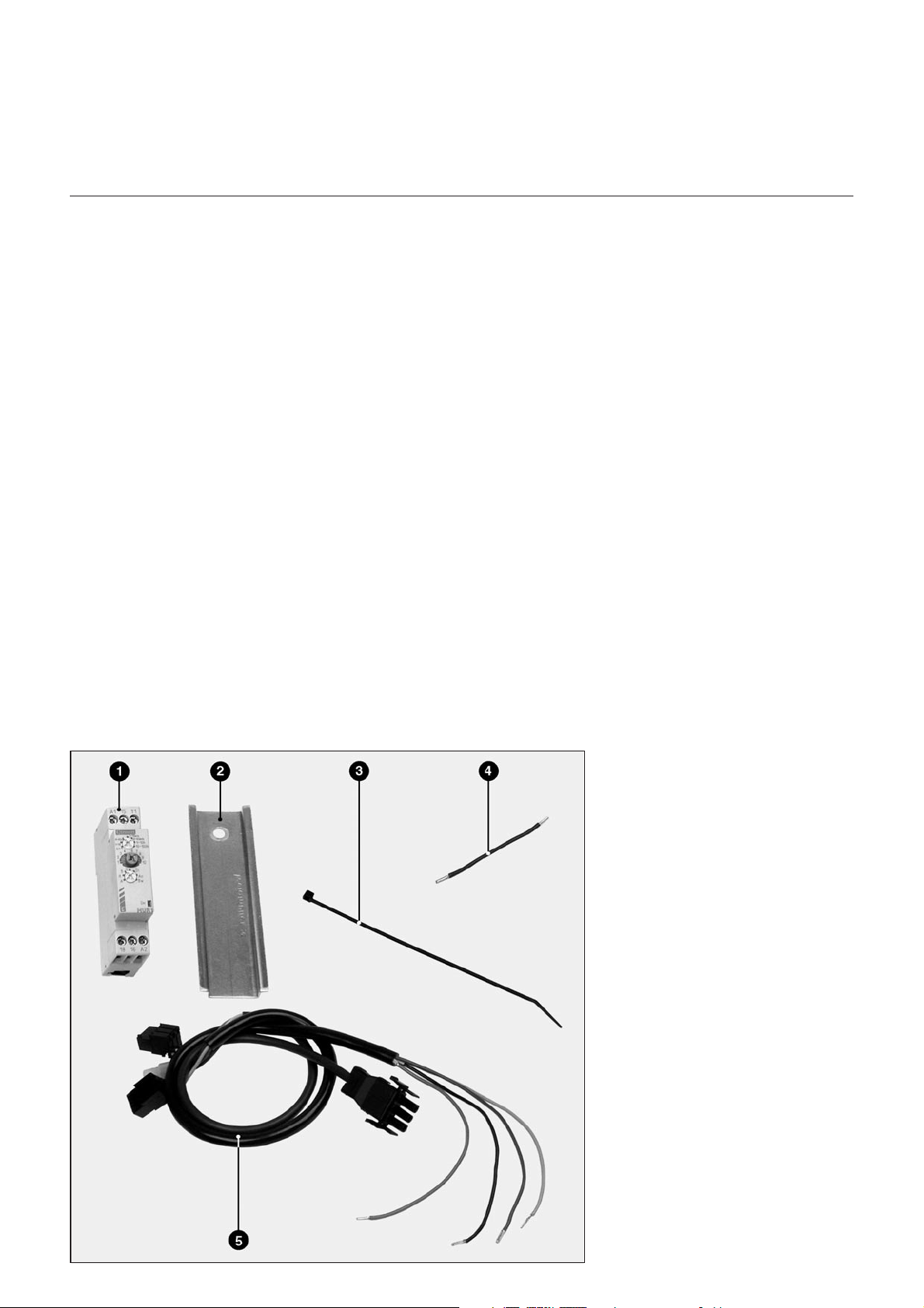
Der Bausatz umfasst :
–ein Relais,
–ein Kabelset,
–1 schwarzen Draht
–1 DIN-Schiene, 118 mm Länge,
–5 Kabelbinder,
–1 Elektroschema,
–1 Montageanleitung
Schlüsselwörter
1Zeitrelais
2DIN-Schiene, 118 mm Länge
3Kabelbinder (x5)
4Kabelset
5 Schwarzer Draht

3
06/2004 - Art. Nr. 13 014 291A
Montage
lDie Stromzufuhr und die Brenns-
toffzufuhr der Anlage abschalten.
Stromabwesenheit überprüfen.
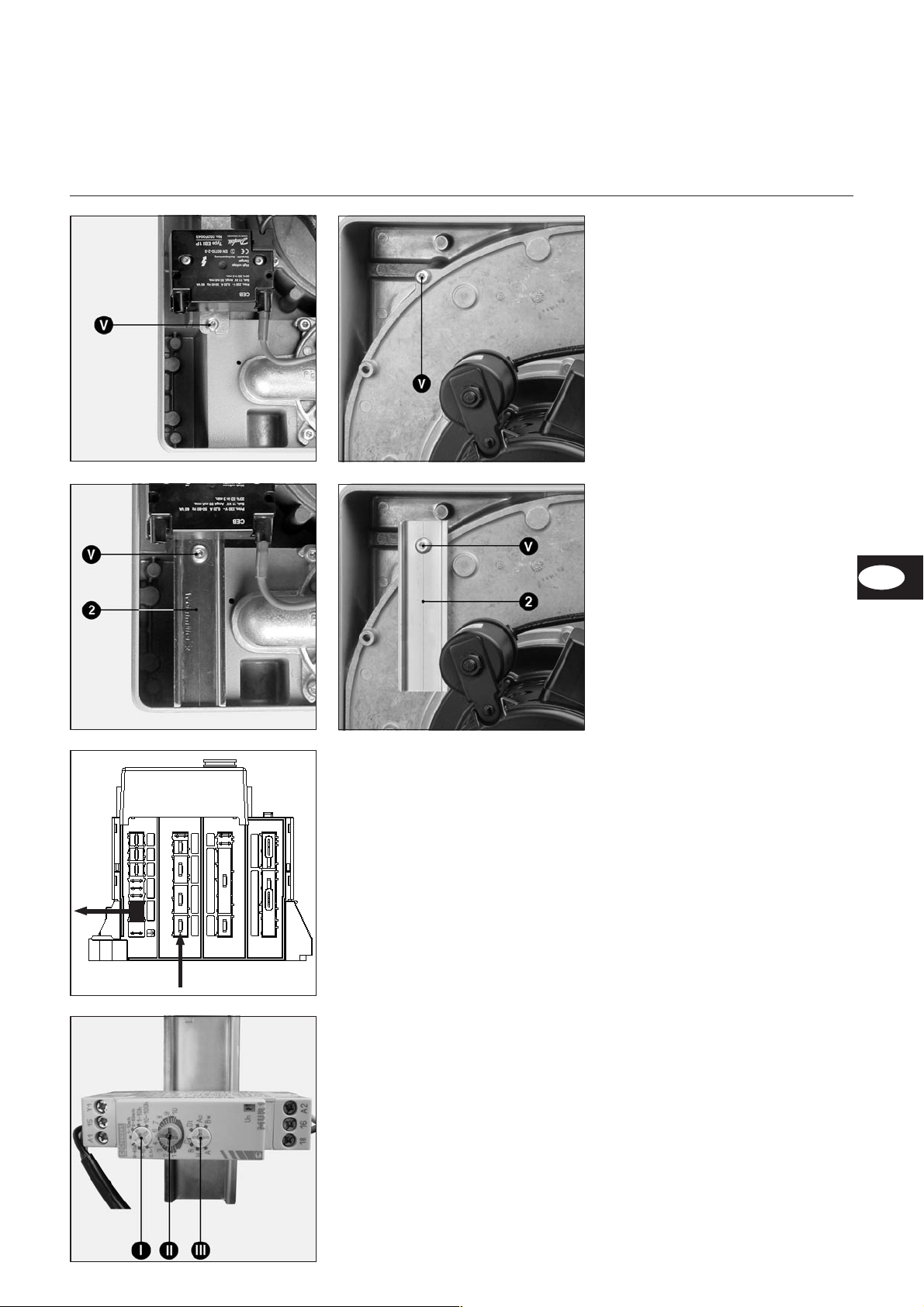
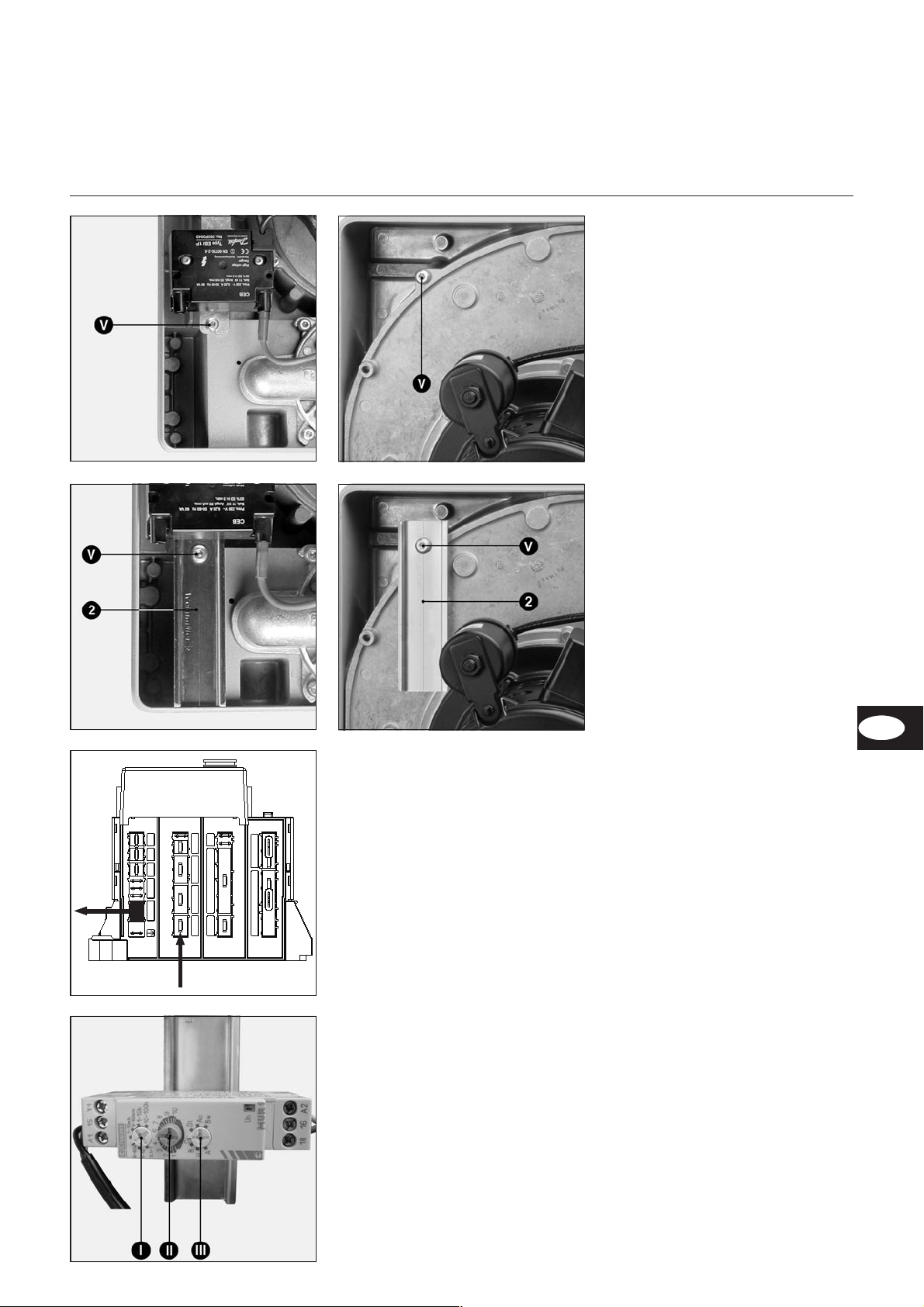
·Brennerhaube demontieren.
·Schraube Vabmontieren.
20
21
10
1/8
4/24
211
22
6
5
23
-/4
25
26
·Die DIN-Schiene 2auf der Elektro-
platine mit der Schraube Vbefesti-
gen.
Zeitrelaiseinstellung
·Folgende Parameter einstellen :
–Index I: Zeitbereich auf 6-60 s.
–Index III : auf C.
–Index II : Multiplizierkoeffizient auf
4(ca.22sek.).
·Spannung wieder herstellen.
·Das korrekte Funktionieren überprü-
fen.
·Die Einstellung falls nötig über +bzw.
-auf Skalenscheibe Everfeinern.
·Die Gesamteinstellung überprüfen.
·Brennerhaube montieren.
·Am Sockel des Feuerungsautomaten :
–Stecker zum Gebläsemotor aus
Steckbuchse 4/24 (D) ausstecken
–die Schutzabdeckung 6ausbre-
chen.
·Motorkabel ausstecken und in der
Dokutasche aufbewahren.
·Kabel 5und schwarzen Draht 4auf
Zeitrelais 1gemäß mitgelieferten
Schaltplan verdrahten.
mAm Steckplatz 6des Automaten-
sockels muß der Neutralleiter
nach Geräteplatte gerichtet
montiert werden.
·Das Zeitrelais 1auf die Schiene 2
aufstecken.
·Die Drähte ordnen und befestigen.
EK03B
EK03B EK04B
EK04B
DE

406/2004 - Art. Nr. 13 014 291A
Table of contents
General information
Description
Table of contents
General informations..................4
Important.......................................4
Description....................................4
Assembly.....................................5
Notes.....................................10-11
Important information
This document is intended to guide
personal qualified in the installation.
Installation and startup must be
performed by a qualified and authorized
technician, in accordance with trade
practices. Both the applicable
regulations and the instructions given in
this manual must be fully complied with.
Any failure - even partial - to observe
these provisions shall absolve the
manufacturer from any liability.
Safety of material and personal
Shut off power supply.
Failure to do so may result in personal
injury or death.
Electrical connection
The set must be wired according to
delivered electrical diagram. Installation
protection and earthing must comply
with applicable regulations.
Modifications made relating to the
installation of this kit must be written in
the burner’s electrical diagram.
Function
The post-ventilation kit enables
ventilation to be continued after the
motor signal coming from the control
and safety unit has been cut off.
Description
The kit contains:
–a delay switch,
–a wiring bundle,
–a black wire,
–a section (118mm long),
–5 wiring straps,
–1 wiring diagram,
–1 set of assembly instructions.
Key words
1Delay switch
2Section (118 mm long)
3Wiring strap (x5)
4 Black wire
5 Wiring bundle

5
06/2004 - Art. Nr. 13 014 291A
lShut off power supply and fuel
supply.
Check there’s no voltage.
·Remove the burner cover.
·Remove the screw V.
Montage
Delay switch setting
·Setting :
–Item I: the time range on 6-60s.
–Item III : position C.
–Item II: time base coefficient on 4
(or »22 s).
·Switch burner on.
·Check it is working correctly.
·Refine +or –if necessary on E.
·Check the whole assembly.
·Re-assemble the burner cover.
20
21
10
1/8
4/24
211
22
6
5
23
-/4
25
26
·Fasten section 2to the plate using
screw V.
·Click the delay switch onto the
section.
·On the unit base :
–remove the fan motor connector
from housing 4/24,
–break protective cap 6.
·Disconnect the cable motor power
supply and put it into the document
folder provided.
·Connect wiring bundle 5and black
wire 4on the delay switch 1, making
sure you follow the electrical diagram
provided.
mOn socket 6of the unit base, the
neutral must be directed towards
the plate.
·Click the delay switch 1onto the
section 2.
·Arrange and attach the wires.
EK03B
EK03B EK04B
EK04B
EN

606/2004 - Art. Nr. 13 014 291A
Table des matières
Informations générales
Descriptif
Table des matières
Informations générales ..............6
Important.......................................6
Descriptif.......................................6
Installation...................................7
Notes.....................................10-11
Avertissement
Le présent document s’adresse
uniquement à des personnes
compétentes. L’installation ainsi que la
mise en service doivent être réalisées
dans les règles de l’art par un
technicien qualifié. Les prescriptions en
vigueur ainsi que les instructions de
cette documentation doivent être
respectées. La non-application même
partielle de ces dispositions pourra
conduire le diffuseur à dégager sa
responsabilité.
Sécurité du matériel et des personnes
Prenez soin de désolidariser le brûleur
de son alimentation.
Le non-respect de ces consignes peut
entraîner des blessures graves, voire
irréversibles.
Connexion électrique
Le kit doit être câblé suivant le
document d’accompagnement. Les
protections de l’installation ainsi que la
mise à la terre doivent être conformes
aux normes en vigueur.
Les modifications liées à l’installation
de ce kit doivent être inscrites dans le
schéma électrique du brûleur.
Principe de fonctionnement
Le kit postventilation permet de
poursuivre la ventilation après coupure
du signal moteur provenant du coffret
de commande et de sécurité.
Descriptif
Le kit contient :
–1 relais,
–1 faisceau de câblage,
–1 fil noir,
–1 profilé lg 118mm,
–5 colliers de câblage,
–1 schéma de câblage,
–1 notice de montage.
Légende
1Relais
2Profilé lg 118mm
3Colliers de câblage (x5)
4Fil noir
5Faisceau de câblage
7
06/2004 - Art. Nr. 13 014 291A
Montage
EK03B
20
21
10
1/8
4/24
211
22
6
5
23
-/4
25
26
lCouper :
l’alimentation électrique au
dispositif omnipolaire et l’arrivée
du combustible.
Vérifier l’absence de tension.
·Déposer le capot du brûleur.
·Déposer la vis V.
·Sur le toron :
–démonter de l’emplacement 4/24 le
connecteur du moteur de ventilation,
–briser l'opercule de protection 6.
·Déconnecter le câble d'alimentation
du moteur et le conserver dans la
pochette de documentation fournie.
·Câbler le faisceau 5et le fil noir 4sur
le temporisateur 1selon le schéma
électrique fourni.
mSur l'emplacement 6du socle du
coffret, le neutre doit être orienté
côté platine.
·Encliqueter le temporisateur 1sur le
profilé 2.
·Arranger et attacher les fils.
Réglage du temporisateur
·Régler :
–Repère I: la plage de temps sur
6-60 s.
–Repère III : position C.
–Repère II : le coefficient de la base
de temps sur 4 (soit »22 s.).
·Remettre le brûleur sous tension.
·Vérifier le fonctionnement.
·Affiner si nécessaire en + ou en - sur
le E.
·Contrôler l’ensemble.
·Remonter le capot du brûleur.
EK03B EK04B
EK04B
·Fixer le profilé 2sur la platine avec la
vis V.
FR

806/2004 - Art. Nr. 13 014 291A
Inhoudstafel
Algemene inlichtingen
Beschrijving
Inhoudstafel
Algemene inlichtingen ...............8
Belangrijk ......................................8
Beschrijving...................................8
Montage .......................................9
Notities..................................10-11
Belangrijk
De installatie en het opstarten dienen te
worden uitgevoerd volgens de regels van
de kunst door een erkend technicus.
De van kracht zijnde voorschriften en
de instructies van deze documentatie
dienen in acht te worden genomen.
Indien de voorschriften of een gedeelte
ervan niet worden gevolgd, kan de
constructeur zijn verantwoordelijkheid
afwijzen.
Veiligheid van uitrusting en
personen
Zorg ervoor dat de brander wordt
afgekoppeld van de voeding.
Als deze instructies niet worden nageleefd,
kunnen ernstige en zelfs onherstelbare
letsels worden veroorzaakt.
Elektrische verbinding
De bedrading van de kit moet volgens
bijgaand document worden uitgevoerd.
De zekeringen en de aarding van de
installatie dienen in overeenstemming
te zijn met de van kracht zijnde
normen.
De wijzigingen in verband met de
installatie van deze kit moeten worden
opgetekend op het elektrische schema
van de brander.
Werkingsprincipe
Met de kit postventilatie kan de
ventilatie worden voortgezet na
onderbreking van het motorsignaal door
de bedienings- en veiligheidskast.
Beschrijving
De kit omvat :
–1 relais,
–1 kabelboom,
–1 geprofileerde rail lengte 118mm,
–1 zwarte draad,
–5 kabelbinders,
–1 bedradingsschema,
–1 Montage-handleiding.
Onderschrift
1Relais
2Geprofileerde rail lengte 118mm
3Kabelbinders (x5)
4Zwarte draad
5Kabelboom
9
06/2004 - Art. Nr. 13 014 291A
Montage
20
21
10
1/8
4/24
211
22
6
5
23
-/4
25
26
lDe elektrische voeding naar de
brander op de meerpolige
onderbreker onderbreken, alsook
de brandstoftoevoer.
Controleren dat geen spanning
aanwezig is.
·De kap van de brander demonteren.
·De schroef Vdemonteren.
·Op de sokkel van de
branderautomaat:
–de connector van de
ventilatiemotor op positie 4/24
demonteren,
–het beschermkapje 6openbreken.
·De voedingskabel van de motor
loskoppelen en bewaren in de
bijgeleverde documentatiemap.
·De bundel 5op het net aansluiten en
de zwarte draad 4op de tijdrelais
volgens het bijgeleverde elektrische
schema.
mDe nulleider van aansluitklem 6
van de sokkel van de
branderautomaat bevindt zich
langs de zijde van de
branderplatine.
·De tijdrelais 1vasklikken op het
profiel 2.
·De draden schikken en bevestigen.
Instellen van de tijdschakelaar
·Regelen:
–referentie I: het tijdsverloop s op
6-60s.
–Referentie III: stand C.
–Referentie II : de coëfficiënt van het
tijdsverloop op 4 (of » 22 s.).
·De brander opnieuw onder spanning
stellen.
·De werking controleren.
·Verfijnen indien nodig naar + of naar
– op de II.
·Het geheel controleren.
·De kap van de brander weer
monteren.
·Het profiel 2op de platine bevestigen
met de schroef V.
EK03B
EK03B EK04B
EK04B
NL

10 06/2004 - Art. Nr. 13 014 291A
Notizen
Notes
Notes
Notities

11
06/2004 - Art. Nr. 13 014 291A
Notizen
Notes
Notes
Notities

12 06/2004 - Art. Nr. 13 014 291A
Fabriqué en EU. Made in EU. Hergestellt in der EU.
Document non contractuel. Non contractual document. Angaben ohne Gewähr.
ELCO Klöckner
A - 2544 Leobersdorf
ELCO - MAT N.V./S.A.
Researchpark
Pontbeeklaan 53
B - 1731 Zellik
ELCO Klöckner
Heiztechnik GmbH
D - 72379 Hechingen
ELCO b.v.
Postbus 5057
NL - 1410 AB Naarden
This manual suits for next models
1
Table of contents
Languages:
Popular Fan manuals by other brands

EDM
EDM PDFJY16DB instruction manual

EVOAQ
EVOAQ AQ60 installation manual

Parrot Uncle
Parrot Uncle F6273 Installation & operating instructions

Dometic
Dometic GY20 Instructions for use

Delta Electronics
Delta Electronics Exhaust Fan GFB Series specification

Halton
Halton Vita VHT INSTALLATION, COMMISSIONING AND MAINTENANCE


